2006 LAND ROVER FRELANDER 2 service
[x] Cancel search: servicePage 2625 of 3229
Publ is hed: 11-May-2011
Side Panel Sheet Metal Repairs - B-Pillar Inner Panel
Removal and Installation
Removal
• NOTE: The B-Pillar inner panel is serviced as a separate weld-on panel.
1. The B-Pillar reinforcement is replaced in conjunction with:
Front door
Rear door
Headli ni ng
B-Pillar outer panel
B-Pillar reinforcement
2. Fo r a d d i t i o na l i nf o rma t i o n re l a t i ng t o t hi s re p a i r p ro ce d ure
please see the following:
Fo r a d d i t i o na l i nf o rma t i o n, re f e r t o : Body and Frame
(501-26
Body Repairs - Vehicle Specific Information and Tolerance
Checks, Description and Operation) /
St a nd a rd W o rks ho p P ra ct i ce s
(100-00 Ge ne ra l I nf o rma t i o n,
Description and Operation).
3. Remove the B-Pillar reinforcement.
Fo r a d d i t i o na l i nf o rma t i o n, re f e r t o : B-Pillar Reinforcement
(501-29 Side Panel Sheet Metal Repairs, Removal and
Installation).
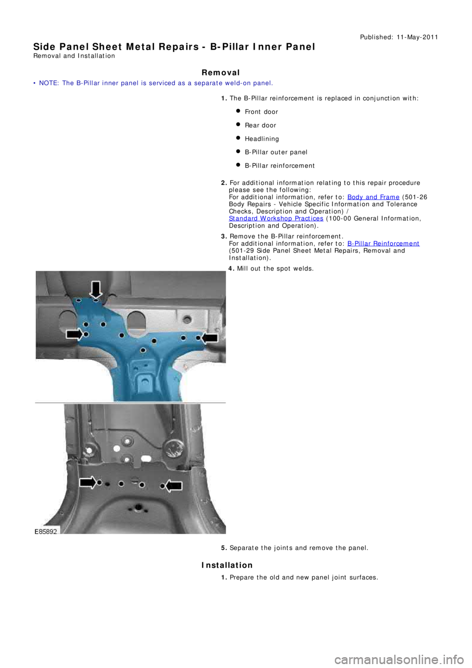
4. Mill out the spot welds.
5. Separate the joints and remove the panel.
Installation
1. Prepare the old and new panel joint surfaces.
Page 2627 of 3229
Publ is hed: 11-May-2011
Side Panel Sheet Metal Repairs - Rocker Panel Inner Reinforcement
Removal and Installation
Removal
• CAUTIONS:
The rocker panel inner reinforcement is DP600, (Dual Phase steel) and must be MIG plug welded to the inner. Spot
we lds must not be used.
Ensure that all welded joints are suitably sealed and waterproofed, particularly in the areas where the original panel
adhesive / sealer cannot be replicated. W here necessary, seal the joints prior to the fitment of outer panels.
• NOTE: The rocker panel inner reinforcement is unpicked from the side panel reinforcement 'ring-frame', it is not serviced
separately.
1. T he ro cke r p a ne l i nne r re i nf o rce me nt i s re p l a ce d i n co nj unct i o n
with:
Front bumper cover
Front fender
Front door
Rear door
Rocker panel
2. Fo r a d d i t i o na l i nf o rma t i o n re l a t i ng t o t hi s re p a i r p ro ce d ure
please see the following:
Fo r a d d i t i o na l i nf o rma t i o n, re f e r t o : Body and Frame
(501-26
Body Repairs - Vehicle Specific Information and Tolerance
Checks, Description and Operation) /
St a nd a rd W o rks ho p P ra ct i ce s
(100-00 Ge ne ra l I nf o rma t i o n,
Description and Operation).
3. Remove the rocker panel.
Fo r a d d i t i o na l i nf o rma t i o n, re f e r t o : Rocker Panel
(501-29 Si de
Panel Sheet Metal Repairs, Removal and Installation).
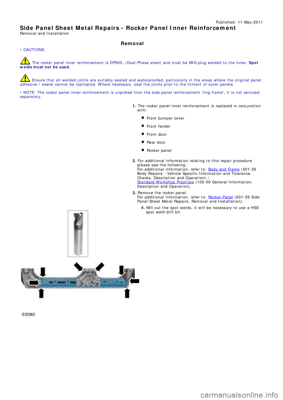
4. Mill out the spot welds, it will be necessary to use a HSS
spot weld drill bit.
Page 2628 of 3229
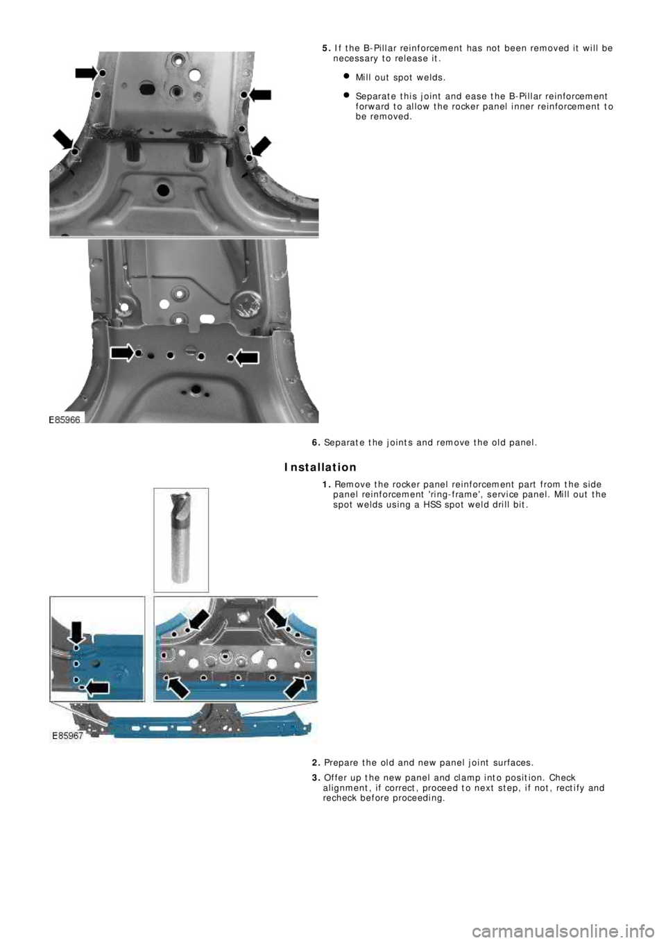
5. I f t he B-P i l l a r re i nf o rce me nt ha s no t b e e n re mo ve d i t w i l l b e
ne ce s s a ry t o re l e a s e i t .
Mill out spot welds.
Separate this joint and ease the B-Pillar reinforcement
f o rw a rd t o a l l o w t he ro cke r p a ne l i nne r re i nf o rce me nt t o
be removed.
6. Separate the joints and remove the old panel.
Installation
1. Remove the rocker panel reinforcement part from the side
panel reinforcement 'ring-frame', service panel. Mill out the
spot welds using a HSS spot weld drill bit.
2. Prepare the old and new panel joint surfaces.
3. Offer up the new panel and clamp into position. Check
al ignment , i f correct , proceed t o next s t ep, i f not , rect i fy and
recheck before proceeding.
Page 2633 of 3229
Publ is hed: 11-May-2011
Rear End Sheet Metal Repairs - Rear End Sheet Metal
Description and Operation
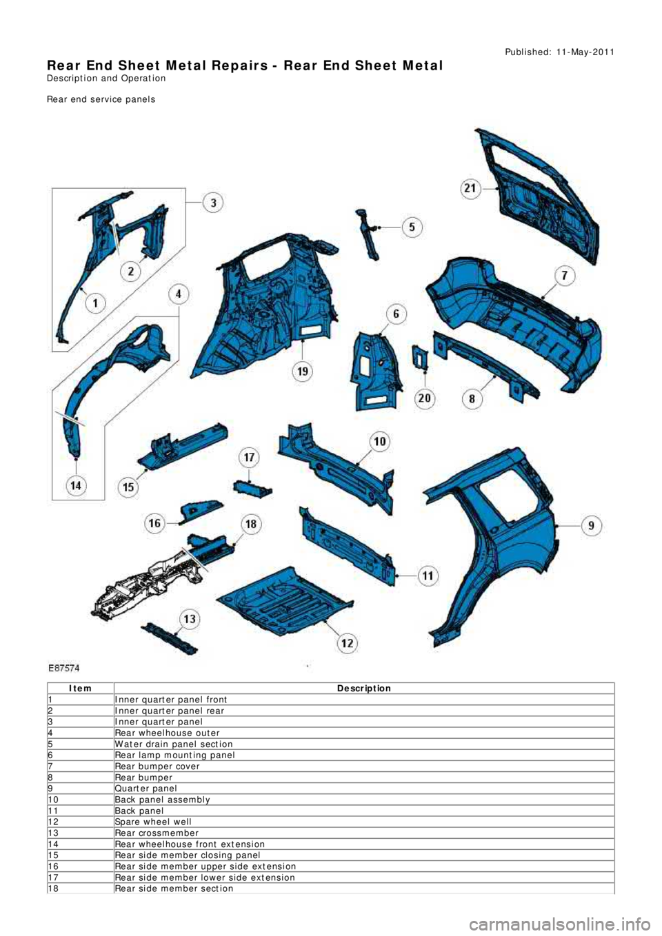
Rear end service panels
Ite m De scr iption
1 Inner quart er panel front
2 I nne r q ua rt e r p a ne l re a r
3 Inner quart er panel
4 Rear wheelhouse outer
5 W ater drain panel section
6 Re a r l a mp mount i ng pa ne l
7 Rear bumper cover
8 Rear bumper
9 Quart er panel
10 Back panel assembly
11 Back panel
12 Spare wheel well
13 Rear crossmember
14 Rear wheelhouse front extension
15 Re a r s i de me mbe r cl o s i ng pa ne l
16 Re a r s i de me mbe r uppe r s i de e xt e ns i on
17 Re a r s i de me mbe r l owe r s i de e xt e ns i on
18 Re a r s i de me mbe r s e ct i on
Page 2636 of 3229
Publ is hed: 11-May-2011
Rear End Sheet Metal Repairs - Quarter Panel
Removal and Installation
Removal
CAUTION: The quarter panel must be MIG slot brazed to the rocker panel inner reinforcement, which is DP600, (Dual
Phase steel). MIG plug we lds / spot w elds must not be use d in this are a.
• NOTE: The quarter panel is serviced as a separate weld-on panel.
• NOTE: There are NVH elements inside this panel, they are not serviced on the new panel. If damaged, a new element
will be required.
1. The quarter panel is replaced in conjunction with:
Rear bumper cover
Rear door
Quarter glass
Headliner
2. Fo r a d d i t i o na l i nf o rma t i o n re l a t i ng t o t hi s re p a i r p ro ce d ure
please see the following:
Fo r a d d i t i o na l i nf o rma t i o n, re f e r t o : Body and Frame
(501-26
Body Repairs - Vehicle Specific Information and Tolerance
Checks, Description and Operation) /
St a nd a rd W o rks ho p P ra ct i ce s
(100-00 Ge ne ra l I nf o rma t i o n,
Description and Operation).
3. Re move t he re a r bumpe r co ve r.
Fo r a d d i t i o na l i nf o rma t i o n, re f e r t o : Rear Bumper
(501-19
Bumpe rs , Re mo va l a nd Ins t a l l a t i on).
4. Remove the rear door.
Fo r a d d i t i o na l i nf o rma t i o n, re f e r t o : Rear Door
(501-03 Body
Closures, Removal and Installation).
5. Remove the headliner.
Fo r a d d i t i o na l i nf o rma t i o n, re f e r t o : Headliner - Vehicles
Without: Tilting Roof Opening Panel (501-05 Int eri or Tri m and
Ornamentation, Removal and Installation) /
Headliner - Vehicles With: Tilting Roof Opening Panel
(501-05
Int erior Trim and Ornamentat ion, Removal and Installat ion).
6. Re mo ve t he re a r d o o r s t ri ke r f ro m t he C-P i l l a r.
7. Remove the roof moulding, front and rear sections.
8. Re mo ve t he s i d e a i r curt a i n mo d ul e .
Fo r a d d i t i o na l i nf o rma t i o n, re f e r t o : Si d e A i r Curt a i n Mo d ul e
(501-20B Suppl ement al Res t rai nt Sys t em, Removal and
Installation).
9. Remove the rear quarter glass.
Fo r a d d i t i o na l i nf o rma t i o n, re f e r t o : Rear Quarter Window
Gl a s s (501-11 Glass, Frames and Mechanisms, Removal and
Installation).
10. Remove the front seat.
Fo r a d d i t i o na l i nf o rma t i o n, re f e r t o : Front Seat
(501-10
Seating, Removal and Installation).
11. Remove the floor console.
Fo r a d d i t i o na l i nf o rma t i o n, re f e r t o : Floor Console
(501-12
Instrument Panel and Console, Removal and Installation).
12. Remove the RH & LH rocker panel inner trims.
13. Remove the rear seat cushion.
Fo r a d d i t i o na l i nf o rma t i o n, re f e r t o : Rear Seat Cushion
(501-10
Seating, Removal and Installation).
14. Re mo ve t he re a r ca rp e t s e ct i o n.
15. Remove the rear safety belt retractor.
Fo r a d d i t i o na l i nf o rma t i o n, re f e r t o : Rear Safety Belt Retractor
(501-20A Safe t y Bel t Sys t em, Removal and Ins t al l at i on).
16. Remove the liftgate aperture weatherseal.
17. Remove the forced air extraction grille.
18. Remove the rear wheel and tire.
Fo r a d d i t i o na l i nf o rma t i o n, re f e r t o : Wheel and Tire
(204-04
Wheels and Tires, Removal and Installation).
19. Remove the rocker panel outer moulding.
20. Release and lay aside the wiring harness along the inner
Page 2642 of 3229
Publ is hed: 11-May-2011
Rear End Sheet Metal Repairs - Rear Side Member Section
Removal and Installation
Removal
• NOTE: The rear side member section is cut from the rear side member service panel. The section is approximately
410mm in length and is serviced with the rear side member lower extension.
• NOTE: It is necessary to remove the spare wheel well to allow access to the rear side member section.
1. The rear side member section is replaced in conjunction with:
Rear bumper cover
Re a r bumpe r a rma t ure
Back panel
Re a r bumpe r mo unt i ng
Inner back panel assembly
Re a r s i de me mbe r cl os i ng pa ne l .
Spare wheel well
Fuel t ank
Rear subframe and suspension assembly
2. Fo r a d d i t i o na l i nf o rma t i o n re l a t i ng t o t hi s re p a i r p ro ce d ure
please see the following:
Fo r a d d i t i o na l i nf o rma t i o n, re f e r t o : Body and Frame
(501-26
Body Repairs - Vehicle Specific Information and Tolerance
Checks, Description and Operation) /
St a nd a rd W o rks ho p P ra ct i ce s
(100-00 Ge ne ra l I nf o rma t i o n,
Description and Operation).
3. Re move t he re a r s i de me mbe r cl os i ng pa ne l .
Fo r a d d i t i o na l i nf o rma t i o n, re f e r t o : Rear Side Member Closing
Panel (501-30 Rear End Sheet Metal Repairs, Removal and
Installation).
4. Remove the rear subframe / suspension as an assembly.
Fo r a d d i t i o na l i nf o rma t i o n, re f e r t o : Rear Subframe
(502-00
Uni-Body, Subframe and Mounting System, Removal and
Installation).
5. Remove the fuel tank.
Fo r a d d i t i o na l i nf o rma t i o n, re f e r t o : Fuel Tank
(310-01A Fuel
Tank and Lines - I6 3.2L Petrol, Removal and Installation).
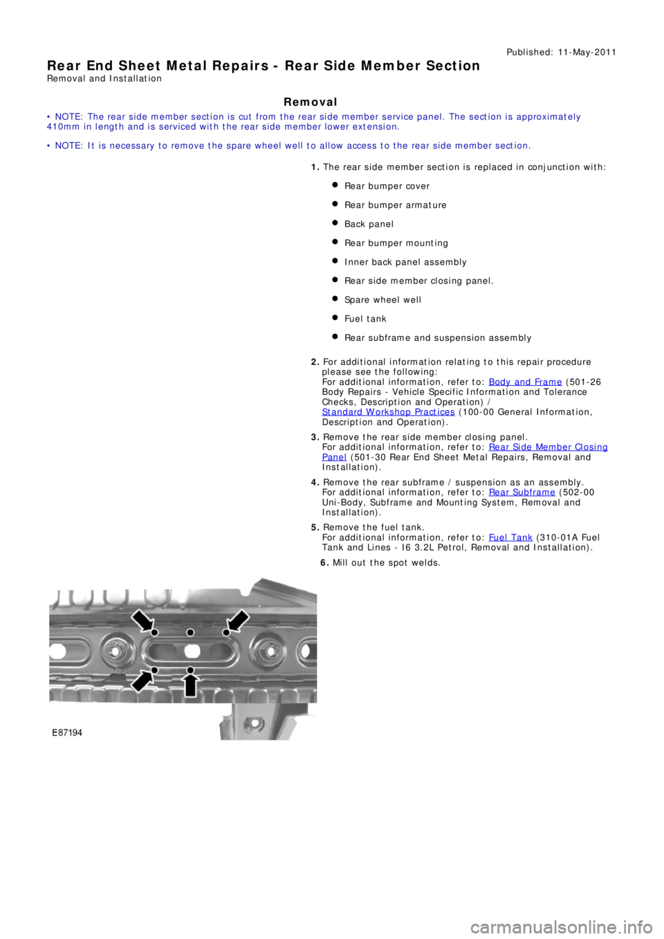
6. Mill out the spot welds.
Page 2643 of 3229
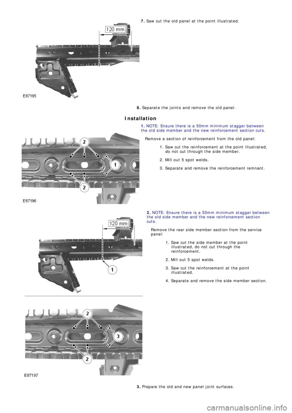
7. Saw cut the old panel at the point illustrated.
8. Separate the joints and remove the old panel.
Installation
1. NO TE: Ens ure t he re i s a 50mm mi ni mum s t a gge r be t we e n
the old side member and the new reinforcement section cuts.
Remove a section of reinforcement from the old panel:
1. Saw cut the reinforcement at the point illustrated,
do not cut through the side member.
2. Mil l out 5 s pot welds .
3. Se p a ra t e a nd re mo ve t he re i nf o rce me nt re mna nt .
2. NO TE: Ens ure t he re i s a 50mm mi ni mum s t a gge r be t we e n
the old side member and the new reinforcement section
cut s .
Remove the rear side member section from the service
panel:
1. Sa w cut t he s i de me mbe r a t t he poi nt
illustrated, do not cut through the
re i nf o rce me nt .
2. Mil l out 5 s pot welds .
3. Saw cut the reinforcement at the point
illustrated.
4. Se pa ra t e a nd re move t he s i de me mbe r s e ct i on.
3. Prepare the old and new panel joint surfaces.
Page 2646 of 3229
Publ is hed: 11-May-2011
Rear End Sheet Metal Repairs - Rear Side Member Closing Panel
Removal and Installation
Removal
• NOTE: The rear side member closing panel is serviced as a separate weld-on panel.
• NOTE: The panel is serviced less its weld studs.
• NOTE: It is necessary to remove the spare wheel well to allow access to the rear side member closing panel.
1. The rear side member closing panel is replaced in conjunction
with:
Rear bumper cover
Re a r bumpe r a rma t ure
Back panel
Re a r bumpe r mo unt i ng
Inner back panel assembly
Re a r s i de me mbe r s e ct i o n
Spare wheel well
Fuel t ank
Rear subframe and suspension assembly
2. Fo r a d d i t i o na l i nf o rma t i o n re l a t i ng t o t hi s re p a i r p ro ce d ure
please see the following:
Fo r a d d i t i o na l i nf o rma t i o n, re f e r t o : Body and Frame
(501-26
Body Repairs - Vehicle Specific Information and Tolerance
Checks, Description and Operation) /
St a nd a rd W o rks ho p P ra ct i ce s
(100-00 Ge ne ra l I nf o rma t i o n,
Description and Operation).
3. Re move t he re a r s i de me mbe r s e ct i on.
Fo r a d d i t i o na l i nf o rma t i o n, re f e r t o : R e a r Si d e Me mb e r Se ct i o n
(501-30 Rear End Sheet Metal Repairs, Removal and
Installation).
4. Remove the rear subframe / suspension as an assembly.
Fo r a d d i t i o na l i nf o rma t i o n, re f e r t o : Rear Subframe
(502-00
Uni-Body, Subframe and Mounting System, Removal and
Installation).
5. Remove the fuel tank.
Fo r a d d i t i o na l i nf o rma t i o n, re f e r t o : Fuel Tank
(310-01A Fuel
Tank and Lines - I6 3.2L Petrol, Removal and Installation).
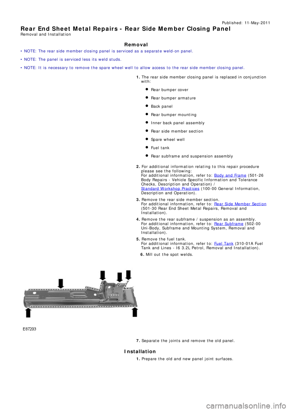
6. Mill out the spot welds.
7. Separate the joints and remove the old panel.
Installation
1. Prepare the old and new panel joint surfaces.