2006 LAND ROVER FRELANDER 2 wheel
[x] Cancel search: wheelPage 278 of 3229

The care point s detai led i n 'Tire Changing' earlier i n t hi s s ect ion must be foll owed to avoi d damage to the sens or. If a news ens or is fi tt ed, a new nut, s eal and was her mus t als o be fit ted and the s ensor nut t ightened t o t he correct torque asgiven i n the Service Repai r Manual .
Instrument Cluster Indications
ItemPart NumberDescription
1-Low ti re press ure warning indicator
2-Mes s age cent reThe warni ng indicati ons to the driver are common on all vehi cl es fi tt ed wi th TPMS. The dri ver i s alerted t o s ys tem warningsby a l ow t ire pres s ure warning i ndi cat or in t he i ns t rument clus ter and an appli cable text mes s age in t he mes s age cent re.
The TPMS s oft ware wit hi n t he CJB pas s es s yst em s t atus i nformat ion to the i nst rument clus ter on t he medi um s peed CANbus. The i nst rument clus t er t hen convert s t his dat a int o il lumi nat ion of t he warni ng indi cat or and di spl ay of an appropriat emes s age.
W hen t he i gni ti on is s wi tched on, the warning i ndi cat or is i ll uminated for 3 s econds for a bul b check.
• NOTE: If the vehicle is not fit ted wi th the TPMS, t he warning indicator wi ll not ill uminat e.
The ins t rument clus ter checks, wit hi n t he 3 s econd bul b check peri od, for a CAN bus mes s age from t he TPMS. Duri ng thi st ime the TPMS performs int ernal tes ts and CAN bus ini ti al is ati on. The warning i ndi cat or wil l be ext inguis hed if t he TPMSs oft ware does not is s ue a faul t mes s age or t ire pres s ure warning mes s age.
If a TPMS faul t warning mess age is det ect ed by t he ins t rument clus ter at ignit ion on, t he warni ng indicator wi ll flas h for 75s econds aft er the 3 s econd bulb check period and t hen remai n permanent ly i lluminated.
If a ti re pres sure warni ng mes sage i s detected by the i nst rument clus t er at i gni ti on on, the warning i ndi cat or wil lexti nguis h briefly after t he 3 s econd bulb check peri od, before re-il lumi nat ing to indicate a ti re pres sure warni ng.
The fol lowing table shows t he warni ng indicat or funct ionali ty for given event s:
EventInstrument Cluster IndicationsLow pres s ure warning l imit reached in hi ghs peed modeW arni ng indicat or i ll uminated. 'TY RE PRESSURES LO W FOR SPEED' mes sagedis played.Low pres s ure warning l imit reached in onewheel in l ow s peed modeW arni ng indicat or i ll uminated. 'CHECK ALL TY RE PRESSURES XX LOW 'mes sage di spl ayed.
Low pres s ure warning l imit reached in moret han one wheel i n low s peed modeW arni ng indicat or i ll uminated. 'CHECK ALL TY RE PRESSURES' mes s agedis played.
W arning l imi t reached in any 'running' wheeland no l ocat ion s peci fi ed by TPMSW arni ng indicat or i ll uminated. 'CHECK ALL TY RE PRESSURES' mes s agedis played.
W arning l imi t reached in s pare wheel (if fit ted)W arni ng indicat or i ll uminated for 20 s econds and again at s ubsequentignit ion cycles . 'CHECK SPARE TY RE PRESSURE' mess age dis played.
TPMS faul tW arni ng indicat or flas hing for 75 s econds and then remains permanent lyil lumi nat ed. 'TY RE PRESSURE MONITORING SY STEM FAULT' mes sagedis played.
Page 280 of 3229
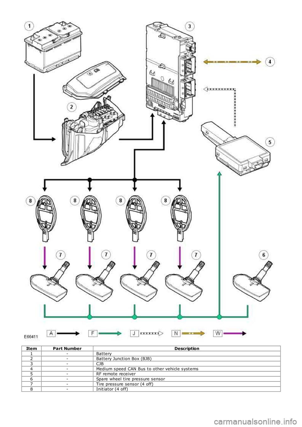
ItemPart NumberDescription
1-Bat tery2-Bat tery Juncti on Box (BJB)
3-CJB
4-Medium s peed CAN Bus t o other vehi cl e s yst ems5-RF remote receiver
6-Spare wheel t ire pres s ure s ensor
7-Ti re press ure sens or (4 off)8-Init iat or (4 off)
Page 281 of 3229
Publi s hed: 11-May-2011
Wheels and Tires - Wheels and Tires
Diagnosi s and Tes ti ng
Principles of Operation
For a detail ed descripti on of the wheel s and ti res and Ti re Press ure Monit oring Sys tem (TPMS), refer t o t he rel evantDes cript ion and Operat ion s ecti on in the works hop manual.REFER to: W heel s and Tires (204-04 W heel s and Tires, Des cri pt ion and Operati on).
Inspection and Verification
CAUTION: Di agnos is by s ubs ti tut ion from a donor vehicle is NO T acceptabl e. Subs ti tut ion of cont rol modules doesnot guarant ee confirmat ion of a faul t, and may als o caus e addit ional fault s i n t he vehi cl e being t est ed and/or t he donorvehi cl e.
1. Verify t he cus t omer concern.1.
2. Vis ually ins pect for, obvi ous si gns of damage and s ys tem int egrit y.2.
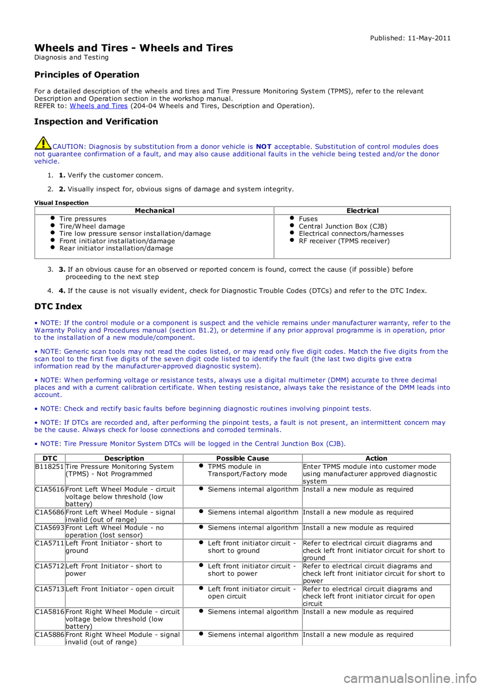
Visual InspectionMechanicalElectrical
Tire pres s uresTire/W heel damageTire l ow pres s ure s ens or i nst all at ion/damageFront i ni ti ator ins t al lat ion/damageRear init iat or ins tall ati on/damage
Fus esCent ral Junct ion Box (CJB)Electrical connect ors /harnes s esRF receiver (TPMS recei ver)
3. If an obvious cause for an obs erved or report ed concern is found, correct t he caus e (if pos s ible) beforeproceeding t o t he next s t ep3.
4. If t he caus e is not vis ually evi dent , check for Di agnos ti c Trouble Codes (DTCs) and refer t o t he DTC Index.4.
DTC Index
• NOTE: If the control modul e or a component i s s us pect and the vehicle remains under manufacturer warrant y, refer t o theW arranty Pol icy and Procedures manual (s ect ion B1.2), or determine i f any pri or approval programme is in operat ion, pri ort o the ins tall ati on of a new module/component.
• NOTE: Generic scan t ool s may not read the codes li st ed, or may read only fi ve digit codes . Mat ch the five di git s from t hes can tool to the firs t fi ve di git s of the seven digi t code l is ted to ident ify t he faul t (t he las t t wo digi ts gi ve ext rainformat ion read by the manufact urer-approved diagnost ic s ys tem).
• NOTE: W hen performing volt age or res is t ance t est s , always use a digi tal mult imeter (DMM) accurat e t o t hree deci malplaces and wit h a current cal ibrat ion cert ificate. W hen tes ti ng res i st ance, always take the res is tance of the DMM l eads i ntoaccount.
• NOTE: Check and recti fy bas ic faul ts before beginni ng diagnos t ic rout ines i nvol vi ng pinpoint t es t s.
• NOTE: If DTCs are recorded and, aft er performi ng the pi npoi nt tes ts , a fault is not present , an int ermi tt ent concern maybe t he caus e. Always check for loose connect ions and corroded terminals .
• NOTE: Tire Pres s ure Moni tor Syst em DTCs will be logged in t he Central Junct ion Box (CJB).
DT CDescriptionPossible CauseAction
B118251Ti re Press ure Monit oring Sys tem(TPMS) - Not ProgrammedTPMS module inTrans port /Fact ory modeEnt er TPMS modul e i nt o cus tomer modeus i ng manufact urer approved diagnost icsys temC1A5616Front Left W heel Module - ci rcuitvolt age below t hres hold (lowbat tery)
Siemens i nternal algori thmIns tal l a new module as required
C1A5686Front Left W heel Module - s ignali nval id (out of range)Siemens i nternal algori thmIns tal l a new module as required
C1A5693Front Left W heel Module - nooperat ion (los t s ens or)Siemens i nternal algori thmIns tal l a new module as required
C1A5711Left Front Init iat or - short togroundLeft front ini ti at or circuit -s hort t o groundRefer to el ect ri cal circui t diagrams andcheck left front i nit iator circui t for s hort t oground
C1A5712Left Front Init iat or - short topowerLeft front ini ti at or circuit -s hort t o powerRefer to el ect ri cal circui t diagrams andcheck left front i nit iator circui t for s hort t opower
C1A5713Left Front Init iat or - open ci rcuitLeft front ini ti at or circuit -open circuitRefer to el ect ri cal circui t diagrams andcheck left front i nit iator circui t for openci rcuitC1A5816Front Ri ght W heel Module - ci rcuitvolt age below t hres hold (lowbat tery)
Siemens i nternal algori thmIns tal l a new module as required
C1A5886Front Ri ght W heel Module - si gnali nval id (out of range)Siemens i nternal algori thmIns tal l a new module as required
Page 283 of 3229
Publi s hed: 11-May-2011
Wheels and Tires - Wheel and Tire
Removal and Inst all ati on
Removal
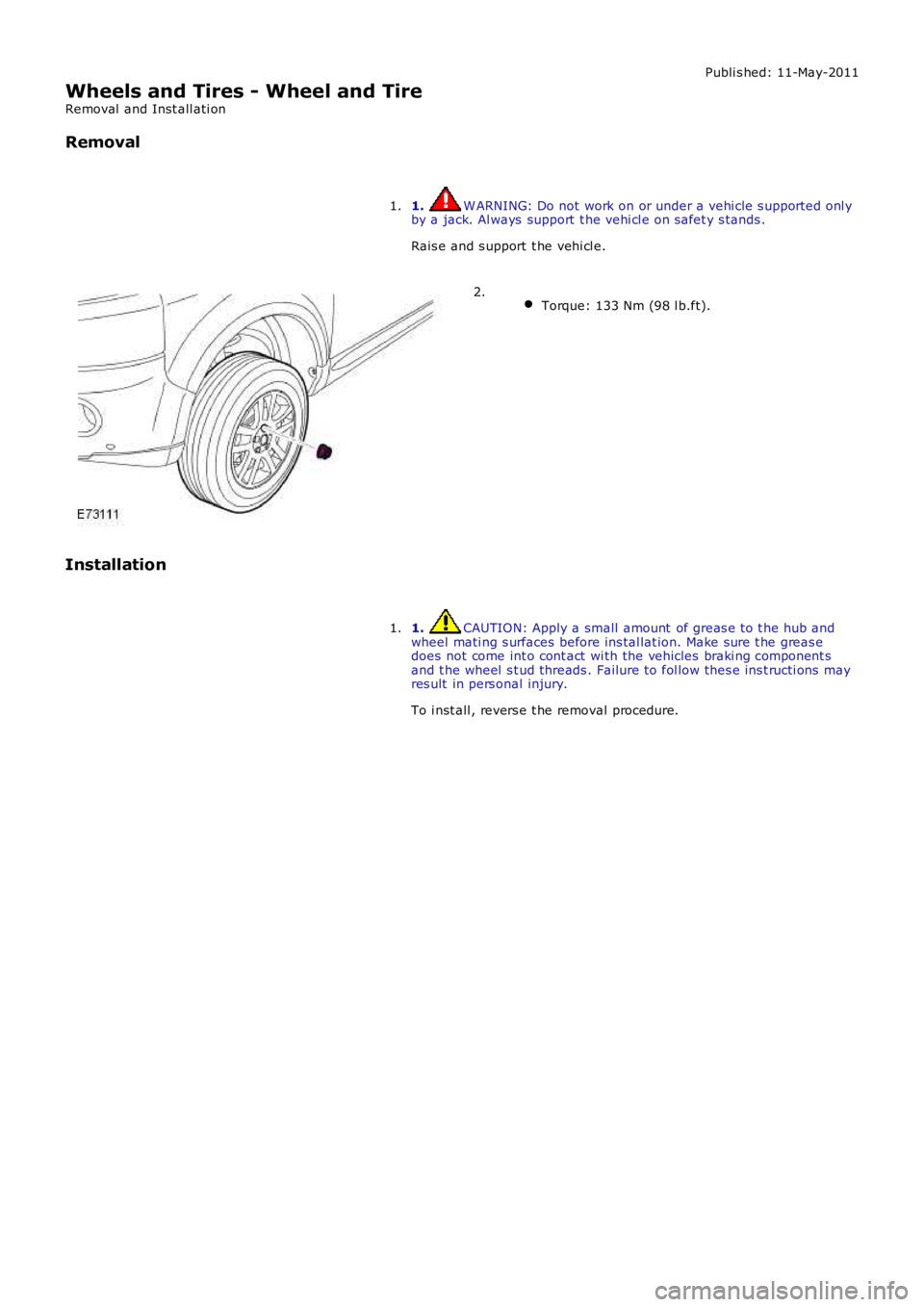
1. W ARNING: Do not work on or under a vehi cle s upported onl yby a jack. Al ways support t he vehi cl e on s afet y s tands .
Rais e and s upport t he vehi cl e.
1.
Torque: 133 Nm (98 l b.ft).2.
Installation
1. CAUTION: Apply a small amount of greas e t o t he hub andwheel mati ng s urfaces before ins tal lat ion. Make sure t he greas edoes not come int o cont act wi th the vehicles braki ng component sand t he wheel s t ud threads . Failure t o fol low thes e ins t ructi ons mayres ult in pers onal injury.
To i nst all , revers e t he removal procedure.
1.
Page 284 of 3229
Publi s hed: 11-May-2011
Wheels and Tires - Tire Low Pressure Sensor
Removal and Inst all ati on
Removal
W ARNING: The val ve seal and s teel was her mus t be replaced each t ime a t ire is changed to avoi d s eal failure. Thes eal and was her must be replaced if t he s ensor i s removed. Removal of the sens or retai ning nut mus t be regarded ass ens or removal. The valve cap mus t always be in pl ace except when i nfl at ing, rel easing or checki ng pres s ure.
• NOTE: If the s ens or i s repl aced on a 'runni ng' wheel, t he new s ens or ident ifi cat ion will be learnt when t he vehi cl e i s fi rs tdri ven. If a new s ensor i s ins t al led t o t he s pare wheel, t he ident ifi cat ion for that s ensor mus t be programmed i nto t he t irepres s ure moni toring s yst em (TPMS) module us ing Land Rover approved di agnos ti c equi pment . The ident ifi cat ion code i sprovided on a label wit h t he compl ete as s embly and i s als o print ed on t he cas ing of each s ens or.
1. W ARNING: Make sure t o s upport the vehicle wit h axles tands .
Rais e and s upport t he vehi cl e.
1.
Remove t he wheel and t ire.
Refer t o: W heel and Ti re (204-04 W heel s and Tires, Removal andInst all at ion).
2.
3. CAUTION: To avoid damage t o t he t ire low pres sure s ens or,rel ease the t ire bead from the rim, 180 degrees from t he val ve.
Remove t he ti re from t he wheel.
3.
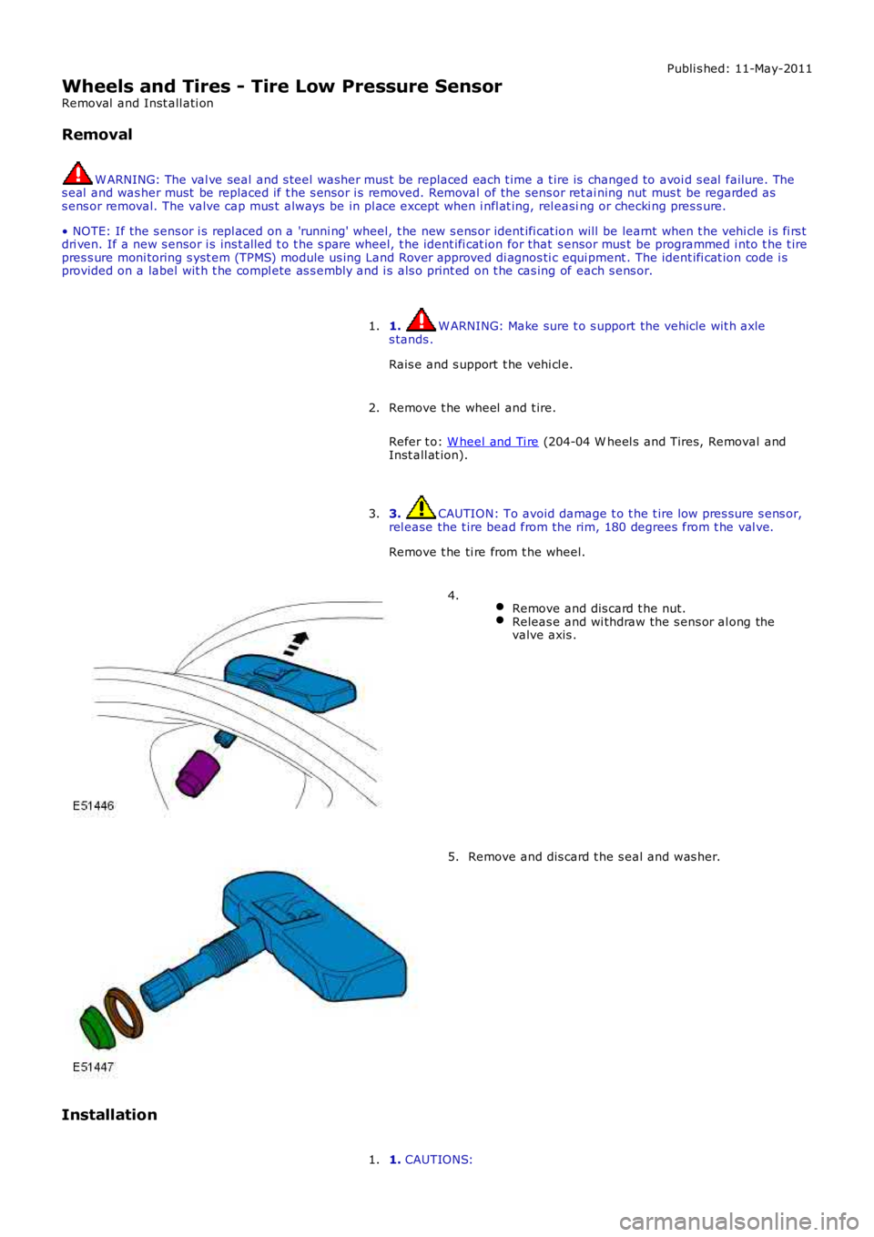
Remove and dis card t he nut.Releas e and wi thdraw the s ens or al ong thevalve axis .
4.
Remove and dis card t he s eal and was her.5.
Installation
1. CAUTIONS:1.
Page 285 of 3229
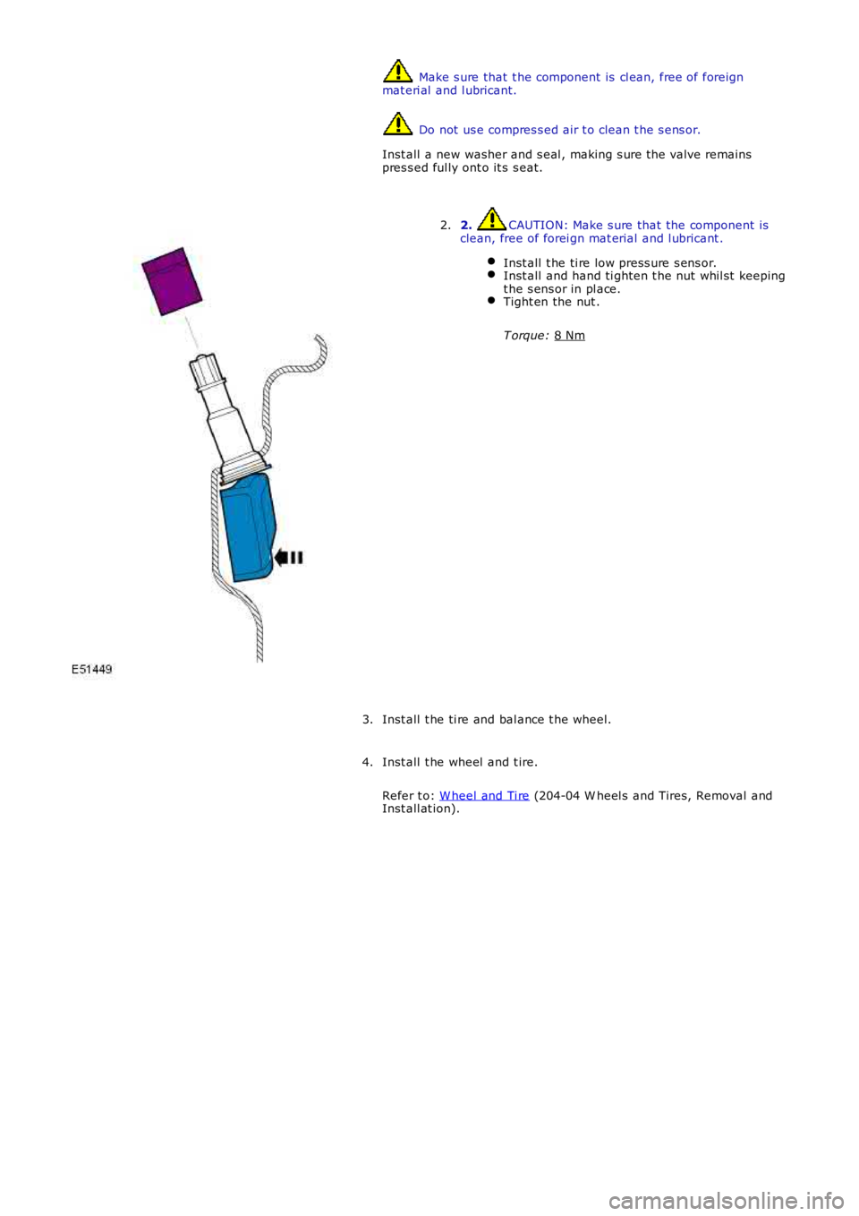
Make s ure that t he component is cl ean, free of foreign
mat eri al and l ubricant. Do not us e compres s ed air t o clean t he s ens or.
Inst all a new washer and s eal , making s ure the valve remains
pres s ed ful ly ont o it s s eat. 2. CAUTION: Make s ure that the component is
clean, free of forei gn mat erial and l ubricant .
Inst all t he ti re low press ure s ens or. Inst all and hand ti ghten t he nut whil st keeping
t he s ens or in pl ace. Tight en the nut .
T orque: 8 Nm 2.
Inst all t he ti re and bal ance t he wheel.
3.
Inst all t he wheel and t ire.
Refer t o: W heel and Ti re (204-04 W heel s and Tires, Removal and
Inst all at ion).
4.
Page 286 of 3229
Publi s hed: 11-May-2011
Wheels and Tires - Tire Pressure Monitoring System (TPMS) Receiver
Removal and Inst all ati on
Removal
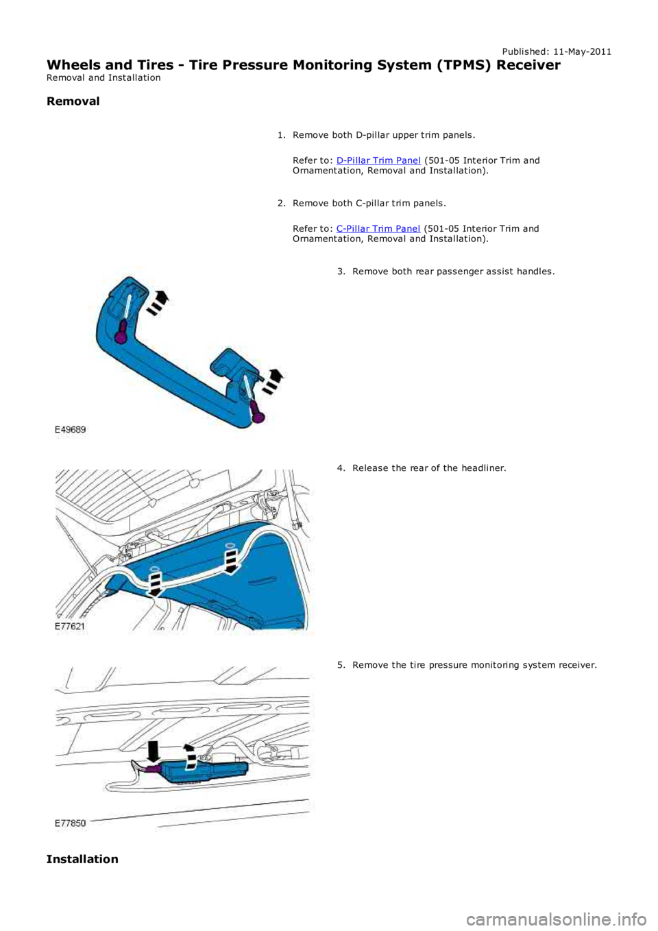
Remove both D-pil lar upper t rim panels .
Refer t o: D-Pi llar Trim Panel (501-05 Int eri or Trim andOrnament ati on, Removal and Ins tal lat ion).
1.
Remove both C-pil lar t ri m panels .
Refer t o: C-Pil lar Tri m Panel (501-05 Int erior Trim andOrnament ati on, Removal and Ins tal lat ion).
2.
Remove both rear pas s enger as s is t handl es .3.
Releas e t he rear of the headli ner.4.
Remove t he ti re pres sure monit ori ng s ys t em receiver.5.
Installation
Page 288 of 3229
Publi s hed: 11-May-2011
Wheels and Tires - Tire Pressure Monitoring System (TPMS) Front Antenna
Removal and Inst all ati on
Removal
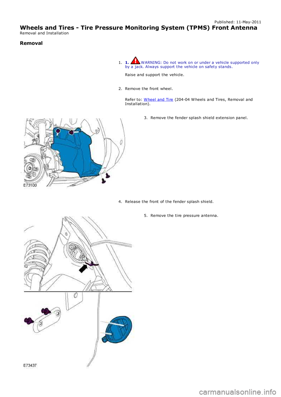
1. W ARNING: Do not work on or under a vehi cle s upported onl yby a jack. Al ways support t he vehi cl e on s afet y s tands .
Rais e and s upport t he vehi cl e.
1.
Remove t he front wheel .
Refer t o: W heel and Ti re (204-04 W heel s and Tires, Removal andInst all at ion).
2.
Remove t he fender spl as h shi el d extens ion panel.3.
Releas e t he front of t he fender s plas h s hi eld.4.
Remove t he ti re pres sure antenna.5.