2006 LAND ROVER FRELANDER 2 wheel
[x] Cancel search: wheelPage 290 of 3229
Publi s hed: 11-May-2011
Wheels and Tires - Tire Pressure Monitoring System (TPMS) Rear Antenna
Removal and Inst all ati on
Removal
1. W ARNING: Do not work on or under a vehi cle s upported onl yby a jack. Al ways support t he vehi cl e on s afet y s tands .
Rais e and s upport t he vehi cl e.
1.
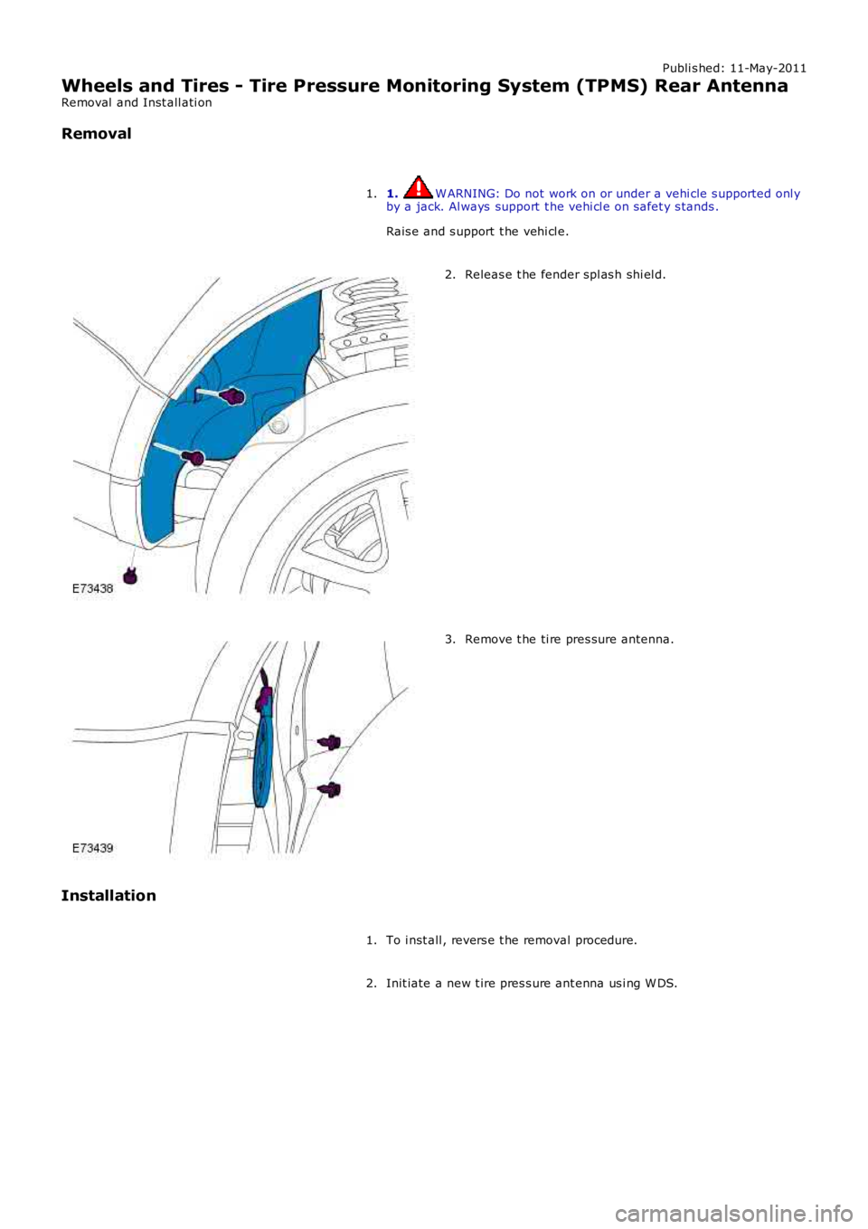
Releas e t he fender spl as h shi el d.2.
Remove t he ti re pres sure antenna.3.
Installation
To i nst all , revers e t he removal procedure.1.
Init iate a new t ire pres s ure ant enna us i ng W DS.2.
Page 291 of 3229
Publi s hed: 11-May-2011
Vehicle Dynamic Suspension - Rear Suspension Height Sensor
Removal and Inst all ati on
Removal
• NOTE: This s ens or i s only fit ted to vehicles wit h Xenon headlamps and is i nst all ed on the LH s ide of t he vehi cl e.
• NOTE: Removal s t eps in t his procedure may cont ain i nst all ati on det ail s.
1. W ARNING: Make sure t o s upport the vehicle wit h axle
s tands .
Rais e and s upport t he vehi cl e.
1.
Remove t he wheel and t ire.
Refer t o: W heel and Ti re (204-04 W heel s and Tires, Removal and
Inst all at ion).
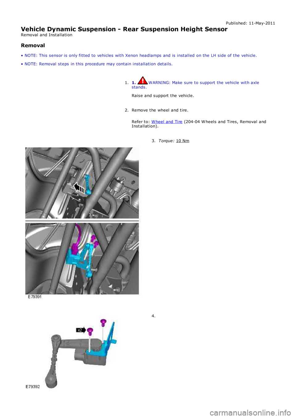
2. T orque:
10 Nm 3.
4.
Page 295 of 3229
Each sub-sys tem operates in di fferent ways in relati on t o t he sel ect ed Terrai n Res pons e program t o achieve t he opt imumt racti on, s t abi lit y and eas e of cont rol for t he t errai n encount ered.
Engine Management System (EMS)
The EMS can change t he accel erator pedal maps to change the amount of t orque per percent age of pedal travel .
Each terrain program uses a combi nat ion of operat ing paramet ers for each sub-sys tem. Changing bet ween terrain programsini ti at es a di fferent s et of operat ing characteris ti cs which wil l be noti ceable to the driver, for example; i f the accel erat orpedal i s held i n a const ant pos i ti on and the terrain program is changed from Gras s /Gravel /Snow t o Sand, the driver wil lnoti ce the t orque and engine s peed increas e. If t he t errai n program is changed from Sand t o Grass /Gravel/Snow, t he dri verwil l not ice a reduct ion in t orque and engine s peed.
• NOTE: The change i n t orque and engine s peed can take approximat ely 30 s econds and care mus t be taken not to confus et he Terrai n Respons e s yst em operat ion wit h an EMS faul t.
Transmission Control (Automatic transmission only)
The t ransmis s ion control modul e changes t he shi ft maps for the Terrain Respons e program s elect ed. Thi s changes t he s hi ftpoints providing early or l at e ups hift s and downs hi ft s .
For example, i n t he Gras s /Gravel /Snow program, the trans mi ss i on wil l perform early ups hi ft s and very late downs hifts toensure t he transmis si on is in t he highes t gear pos si ble. The hil l det ect ion funct ion of t he Trans mis s ion Cont rol module(TCM) will l ock t he t orque converter and hold whi chever gear i s s el ect ed t o t he engine s peed (RPM) li mit i f neces s ary whendescending a s t eep incli ne. This provi des maximum engi ne braking before t he dri ver needs t o appl y t he brakes.
Sport mode i s only avail abl e when t he general program i s s elected. Sport mode i s disabled i n all Terrain Res pons e s peci alprograms. 'CommandShift ™' is avail abl e in any program.
Active On-Demand Coup ling Control
The act ive on-demand coupli ng cont rol module has 2 operati ng s trat egies ; pre-empt ive and react ive.
The pre-empti ve st rat egy anti ci pat es and predict s the locki ng torque val ue required t o mi ni mi ze sl ip and maxi mizes tabil it y. Each Terrain Res pons e program has a different t hres hol d and i nput cri teria for the pre-empt ive s t rategy. Forexampl e, a higher locki ng t orque would be appl ied on s li ppery s urfaces .
The reacti ve s trategy vari es the amount of locking t orque in res pons e t o t he actual s lip level and t he dynamic behavi or oft he vehi cl e. Each Terrain Res pons e program has a different t hres hol d and input for the react ive s trategy. The reacti ves trategy i mproves vehi cl e t racti on and compos ure by eliminati ng any wheel s pin which has occurred aft er the pre-empt ives trategy was appli ed. The l ocking res pons e appli ed is appli cable to the t errain program sel ect ed. For exampl e, verys ens i ti ve on s lippery surfaces to provide maximum t racti on and mi nimi ze surface damage.
The locking t orque calculati ons use various s ignals from other s ub-s yst ems , for example, engi ne torque, accel erator pedalposi ti on, s elect ed gear, st eeri ng angl e, vehicle s peed, lat eral accelerat ion, yaw behavi or.
The DSC funct ion of t he ABS s ys t em can override t he act ive on-demand coupli ng cont rol and reduce any appl ied l ocki ngt orque during DSC act ion.
ABS System Control
The ABS module cont rols several functi ons and adjust s t he operati ng paramet ers of t hes e funct ions t o opti mize thes elect ed Terrain Res pons e program.
Tracti on Control
Tracti on cont rol us es different s li p/accel erati on thresholds to i mprove t ract ion and vehicle compos ure. For example, t hes ys t em s ens it ivit y is increased on s lippery surfaces s uch as wet grass or s now t o reduce wheel s pi n. If wheel s pi n wasall owed in t hese ci rcums tances, l oss of t ract ion may res ul t from surface damage (wet grass ) or t he car being unable tomove (snow) due t o wheel spi n.
Dynamic St abi li ty Cont rol
If DSC is s wi tched off (wit h t he DSC s wi tch adjacent to t he Terrain Res pons e rotary cont rol ) when usi ng a TerrainRespons e s peci al program, if t he s peci al program i s s ubs equent ly changed for a di fferent program, DSC is aut omat icall ys wit ched back on.
The DSC us es different t hres hol d values for t he s elected program t o aut omati call y reduce DSC i ntervent ion, removing t herequirement for t he dri ver t o dis able t he DSC s ys tem in order to reduce engine intervent ion whi ch is s omet imes i nduced i nextreme off-road condi ti ons . In ext reme s and condit ions , there may be an addit ional benefit of dis abling the DSC funct ionus ing t he DSC s wit ch in addi ti on to sel ect ing t he s and program.
In the Mud/Ruts program the DSC sys tem is cal ibrat ed t o tol erate a higher 'yaw' thres hold. This al lows a greaterdifferent ial between t he actual and des i red wheel turni ng behavi or before DSC i ntervenes . Thi s all ows the DSC s ys t em t oignore the effect of rut s 'jarring' t he car or adjust ing t he front wheel s t eering angle.
The Terrai n Res pons e s ys tem can al ter t he balance bet ween engine and brake i ntervention. For example, when t he s andprogram is sel ect ed, t he DSC s ys tem reduces it s rel iance on engi ne int erventi on and increas es the us e of brakeint erventi on to maint ai n t he vehi cl es momentum and prevent it from becomi ng bogged down i f wheel s li p i s detected.
Hil l Descent Cont rol
HDC i s automat icall y s wit ched on or off and target s peeds are adjus t ed in res pons e to t he Terrai n Res pons e programs elect ed. The res pons iveness of the HDC functi on is al so increas ed where requi red.
Automat ic operat ion of HDC ai ms t o as s is t the driver by s wit chi ng t he sys t em on or off when it is of most benefi t. HDC isonly aut omat icall y s wit ched on when the mud/rut s program i s s elect ed. HDC i s not automati cal ly s elected in ot her
Page 300 of 3229
Publi s hed: 11-May-2011
Driveline System - General Information - Driveline System
Diagnosi s and Tes ti ng
Principles of Operation
For a detail ed descripti on of the driveli ne s ys t ems , refer t o t he rel evant Des cript ion and Operat ion s ecti on in the works hopmanual. REFER to:
Dri ves haft (205-01 Driveshaft , Des cript ion and Operat ion),Univers al Joint s (205-01 Dri ves haft , Descripti on and Operat ion),Rear Drive Axle and Different ial (205-02 Rear Drive Axle/Different ial, Des cri pt ion and Operati on),Front Dri ve Axl e and Di fferenti al (205-03 Front Drive Axle/Different ial, Des cript ion and O perati on),Front Dri ve Halfs haft s (205-04 Front Drive Halfs hafts , Des cript ion and Operat ion),Rear Drive Hal fs haft s (205-05 Rear Drive Halfs hafts , Des cript ion and Operat ion).
Inspection and Verification
CAUTION: Di agnos is by s ubs ti tut ion from a donor vehicle is NO T acceptabl e. Subs ti tut ion of cont rol modules doesnot guarant ee confirmat ion of a faul t, and may als o caus e addit ional fault s i n t he vehi cl e being t est ed and/or t he donorvehi cl e.
• NOTE: Cert ain driveli ne s ympt oms are als o common t o t he engine, trans mi s si on, wheel bearings , ti res , and other part sof the vehicle. For thi s reas on, ens ure that t he caus e of t he troubl e is in t he driveline before adjus t ing, repairing, orins t al li ng any new components .
1. Verify t he cus t omer concern.1.
2. Vis ually ins pect for s ys tem int egrit y and obvi ous s igns damage.2.
3. If an obvious cause for an obs erved or report ed concern is found, correct t he caus e (if pos s ible) beforeproceeding t o t he next s t ep3.
4. If t he caus e is not vis ually evi dent , verify t he sympt om and refer t o t he Sympt om Chart, al ternat ively, check forDi agnos ti c Trouble Codes (DTCs) and refer t o t he DTC Index.4.
Identify the Condition
Gear Howl and W hine
Howli ng or whining of t he ring gear and pi nion i s due t o an incorrect gear patt ern, gear damage or i ncorrect beari ngprel oad.
Bearing W hine
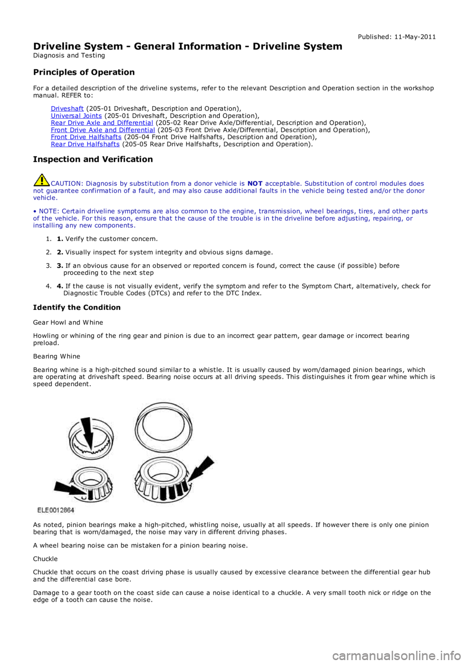
Bearing whine i s a high-pi tched s ound si mi lar to a whis t le. It is us ually caus ed by worn/damaged pi nion beari ngs , whichare operat ing at drives haft s peed. Bearing noi se occurs at al l drivi ng speeds . Thi s dis ti ngui s hes i t from gear whine whi ch iss peed dependent .
As noted, pini on bearings make a hi gh-pit ched, whis t li ng noi s e, us ually at al l s peeds . If however t here i s only one pi nionbearing that is worn/damaged, the nois e may vary i n different driving phas es .
A wheel bearing noi se can be mis t aken for a pini on bearing nois e.
Chuckle
Chuckle that occurs on t he coas t dri vi ng phas e is us ual ly caus ed by exces si ve clearance between t he different ial gear huband t he different ial cas e bore.
Damage t o a gear toot h on t he coas t s ide can cause a nois e i dent ical t o a chuckl e. A very s mal l tooth nick or ri dge on theedge of a t oot h can caus e t he nois e.
Page 302 of 3229
Bearing Rumbl e
Bearing rumble s ounds l ike marbl es being t umbled. Thi s condi ti on is us uall y caus ed by a worn/damaged wheel bearing.The lower pit ch is because the wheel bearing turns at onl y about one-t hird of the drives haft s peed. W heel bearing nois eals o may be high-pi tched, s imil ar t o gear noi s e, but wi ll be evident in al l four drivi ng modes.
Symptom Chart
SymptomPossible CauseActionNois e i s at cons t ant t oneover a narrow vehi cl e s peedrange. Us ual ly heard onl ight drive and coas tcondi ti ons
Rear drive axl eFor addi ti onal i nformat ion. GO to Pi npoi nt Tes tA.
Nois e i s t he s ame on driveor coas tRoad nois eW orn or damaged dri ves haftjoi ntDriveshaft cent er beari ngW heel bearing
Normal condit ion (road noi se)Check and ins tal l new components a required.REFER t o:Driveshaft - Vehi cl es W i thout: Di eselPart iculat e Fil ter (DPF) (205-01Driveshaft, Removal and Ins tall ati on),Rear W heel Bearing (204-02 RearSus pens ion, Removal and Inst all at ion),Front W heel Bearing (204-01 FrontSus pens ion, Removal and Inst all at ion).
Nois e i s produced wit h t hevehicle s t ati onary andwhen driving
EngineTrans mi ss ionFor addi ti onal i nformat ion. REFER to:Engine (303-00 Engine Syst em - GeneralInformat ion, Di agnos is and Tes ti ng),Di agnos ti cs (307-01 Aut omati cTrans mi ss ion/Transaxle, Di agnos is andTes ti ng).
Loud clunk in the driveli newhen s hifti ng from revers et o forward
Trans mi ss ion cal ibrat ionTrans mi ss ion MountTrans mi ss ionSus pens ion component sBackl ash in t he dri vel ineEngine i dl e s peed s et t oo highEngine mount
Us i ng the manufact urer approved diagnos t ics ys tem, re-configure t he Transmis s ion ControlModule (TCM) wi th the l ates t avai lablecali brati onIns pect and ins t al l new t ransmis s ion mount sas requi redFor t ransmis s ion diagnos ti cs .REFER t o: Diagnos t ics (307-01 Automat icTrans mi s si on/Trans axl e, Diagnos is andTes ti ng).Ins pect and ins t al l new s uspens ioncomponent s as requi redIns pect and ins t al l new dri vel ine component sas requi redCheck and adjus t the i dle s peed as requi redIns pect and ins t al l new engi ne mounts asrequi red
Cli cki ng, popping, orgri nding nois esInadequate or contami nat edl ubricati on in the front /reardri ve halfshaft cons tant veloci ty(CV) jointAnother component cont act ingt he front/rear dri ve hal fs haftW heel bearings , brakes ors uspens ion component s
Ins pect, cl ean and lubri cat e wit h new greaseas requi redEns ure al l ot her components are clear fromfront /rear drive halfs haftIns pect and ins t al l new components asrequi red
Vibrati on at highways peedsOut of balance wheel (s ) ort ire(s )Driveshaft mis ali gned/out ofbalanceDriveshaft cent er beari ngt ouching body mount ing point
Bal ance and i ns t all new wheel(s ) and ti re(s) asrequi red.REFER t o: W heel and Ti re (204-04 W heel s andTi res , Removal and Ins t allat ion).Check dri ves haft ali gnment . Check drives haftbalance us ing manufact urer approveddi agnos ti c s ys t emCheck dri ves haft ali gnment
Shudder, Vibrat ion DuringAccel erati onPowert rai n/dri vel inemi s al ignmentHi gh cons tant velocit y (CV) jointoperat ing angles caus ed byi ncorrect ride hei ght
Check for powert rai n/dri vel ine mis alignmentand rect ify as requi red. Ins t al l newcomponent s as requi redCheck the ri de hei ght and verify the corrects pri ng rat e. Ins t al l new components asrequi red
Lubricant LeakRear drive axl e breatherDamaged s ealRear drive axl e fi ll er pl ugRear drive axl e cover/acti veon-demand coupl ing joint
Check oil level and correct as neces s aryIns tall new drives haft/pinion seal as required.REFER t o: Act ive On-Demand Coupl ing DrivePi ni on Seal (205-02 Rear Dri veAxle/Different ial , Removal and Ins t al lat ion).Check and ins tal l new fi ll er pl ug as requiredRe-seal leaking joint s as required
Page 319 of 3229
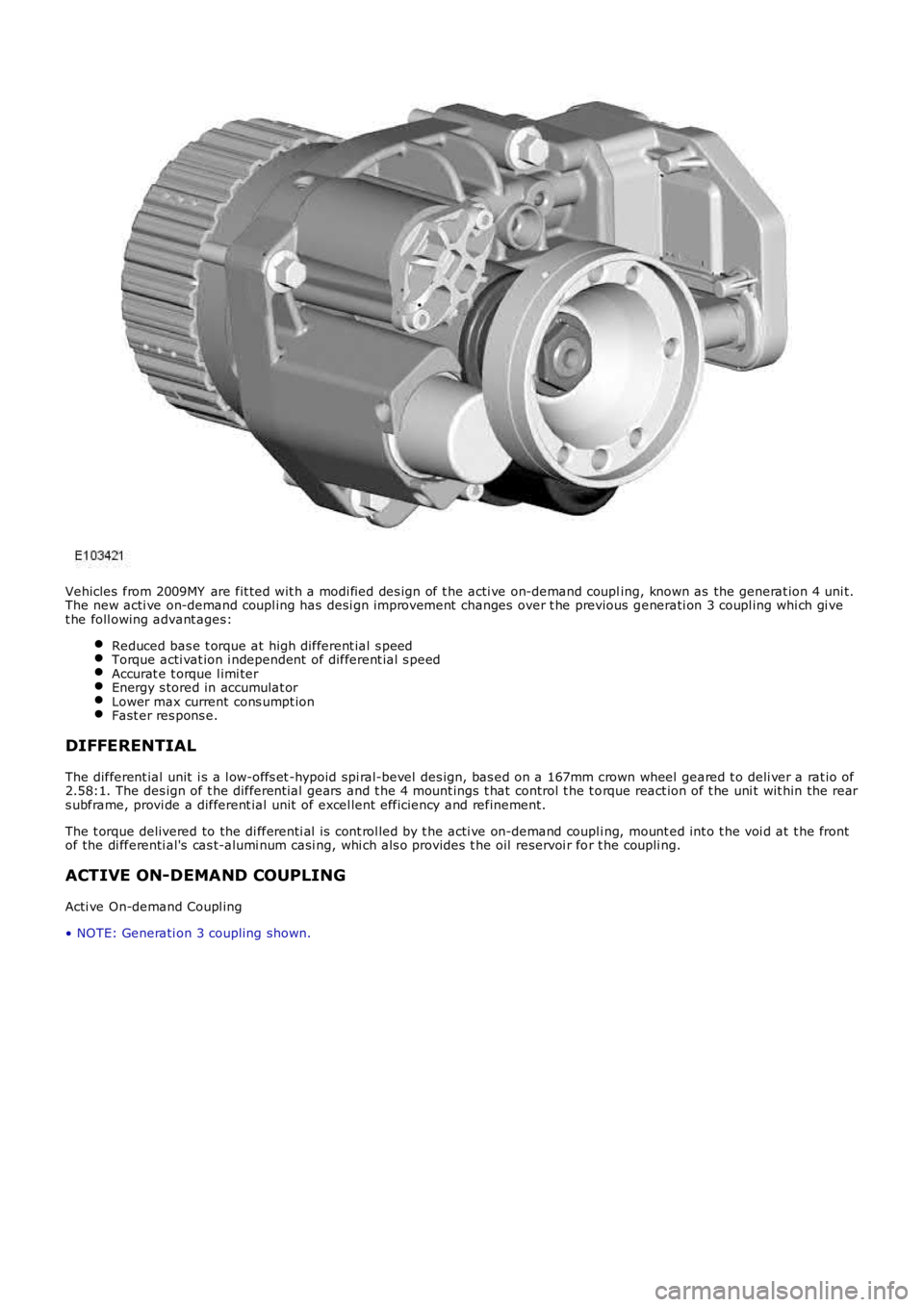
Vehicles from 2009MY are fit ted wit h a modi fied des ign of t he acti ve on-demand coupling, known as the generat ion 4 uni t.The new acti ve on-demand coupl ing has desi gn improvement changes over t he previous generati on 3 coupl ing whi ch gi vet he foll owing advant ages:
Reduced bas e t orque at high different ial s peedTorque acti vat ion i ndependent of different ial s peedAccurat e t orque l imi terEnergy s tored in accumulat orLower max current cons umpt ionFast er res pons e.
DIFFERENTIAL
The different ial unit i s a l ow-offs et -hypoid spi ral-bevel des ign, bas ed on a 167mm crown wheel geared t o deli ver a rat io of2.58:1. The des ign of t he different ial gears and t he 4 mount ings t hat control t he t orque react ion of t he uni t wit hin the rears ubframe, provi de a different ial unit of excel lent efficiency and refinement.
The t orque delivered to the di fferenti al i s cont rol led by t he acti ve on-demand coupli ng, mount ed int o t he voi d at t he frontof the di fferenti al's cas t-alumi num casi ng, whi ch als o provi des t he oil reservoi r for t he coupli ng.
ACTIVE ON-DEMAND COUPLING
Acti ve On-demand Coupl ing
• NOTE: Generati on 3 coupling shown.
Page 320 of 3229
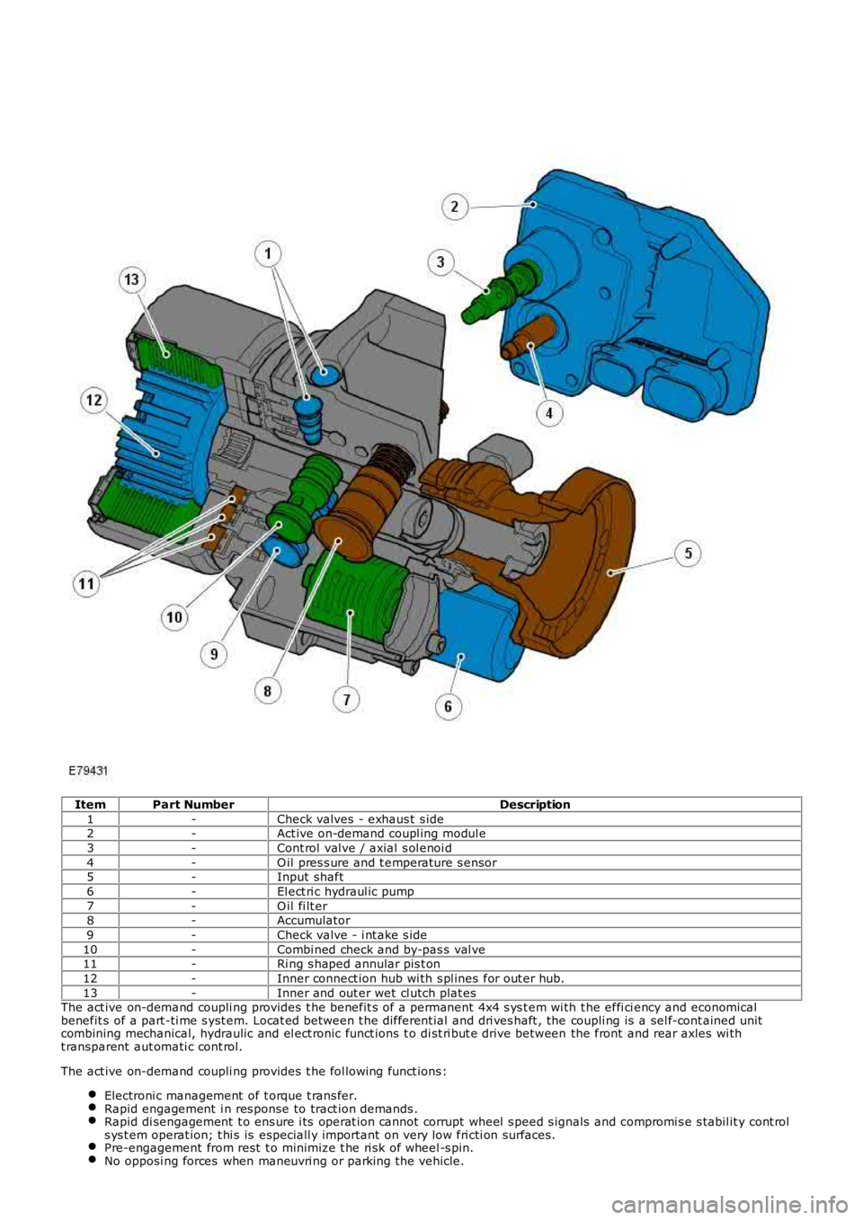
ItemPart NumberDescription
1-Check valves - exhaus t s ide2-Act ive on-demand coupl ing modul e
3-Cont rol val ve / axial s ol enoi d
4-O il pres s ure and t emperature s ensor5-Input shaft
6-El ect ri c hydraul ic pump
7-O il fi lt er8-Accumulator
9-Check valve - i nt ake s ide
10-Combi ned check and by-pas s val ve11-Ri ng s haped annular pis t on
12-Inner connect ion hub wi th s pl ines for out er hub.
13-Inner and out er wet cl utch plat esThe act ive on-demand coupli ng provides t he benefit s of a permanent 4x4 s ys t em wi th the effi ci ency and economicalbenefit s of a part -ti me s yst em. Locat ed between t he different ial and dri ves haft , the coupli ng is a sel f-cont ained unitcombining mechanical, hydraulic and el ect ronic funct ions t o di st ri but e drive between the front and rear axles wi tht ransparent aut omati c cont rol.
The act ive on-demand coupli ng provides t he fol lowing funct ions :
Electroni c management of t orque t rans fer.Rapid engagement i n res ponse to tract ion demands .Rapid di sengagement t o ens ure i ts operat ion cannot corrupt wheel s peed s ignals and compromi s e s tabil it y cont rols ys t em operat ion; t hi s is especiall y important on very low fri cti on surfaces.Pre-engagement from rest t o minimize t he ri sk of wheel -s pin.No opposi ng forces when maneuvri ng or parking t he vehicle.
Page 321 of 3229
Not s ens it ive to brake tes ti ng on a chas si s dynamomet er.
Generati on 4 Acti ve On-Demand Coupli ng - Vehicles from 2009MY
The generati on 4 coupl ing does not have the di fferenti al s peed dri ven pump used on the previ ous generat ion 3coupl ing, but i s fit ted wi th a bigger capacit y electrically operated axial pump and a hi gh pres s ure accumul ator.The proport ional throt t le valve and press ure s ens or on t he generat ion 3 coupli ng is replaced wit h a proport ionalpres s ure reducing val ve.The t orque li mit er pres sure reducing valve on the generat ion 3 coupli ng is replaced by an electroni c cont rol valveand cont rol ling software.
The generati on 4 acti ve on-demand coupli ng gives t he fol lowing improvements over t he previous generati on 3 coupl ing:
Reduced bas e t orque at high different ial s peedsTorque acti vat ion i s now i ndependent of different ial s peedAccurat e t orque l imi ter cont rolEnergy s tored in hi gh pres s ure accumul ator givi ng a low maximum current consumpt ion of t he electric pump andfas t er res pons e.
Control Module - G eneration 3 and 4 Couplings
The cont rol module, at tached to the cas ing of t he act ive on-demand coupling, forms a s ingle unit wit h t he cont rolvalve/axial s ol enoi d. By anal yzi ng informat ion from other vehi cl e modules and s ensors t he cont rol module regul ates t heaxial sol enoi d t o cont rol t he hydraul ic flui d pres s ure s uppl ied t o t he clut ch pl ates. Some of t he modul es and s ens ors thecont rol module communi cat es wit h are li s ted below:
Hardwi red:- Control valve / axi al s olenoid- Electric hydrauli c pump- Oi l press ure and temperat ure sens orHigh speed CAN (cont rol ler area net work):- Engine cont rol module- Anti -l ock brake s ys t em / t racti on cont rol module- Tracti on res ponse swit ch- Y aw rate sens or- Steering wheel rot at ion sens or
The axial sol enoi d cons t ant ly adjust s t he cont rol valve output us ing a Pul se W i dt h Modulat ion (PW M) s i gnal. The flui dpres s ure deli vered t o t he cl utch plat es determines t he amount of t orque t hat is delivered t o t he rear axl e.
The act ive on-demand coupli ng has int egrated oi l press ure and temperature s ens ors to enable the control modul e t oaccurat ely manage t he t orque t ransfer under all environment al and operat ing condit ions . Usi ng thes e s ignals the controlmodule will us e s t rategi es to protect the coupli ng from overheati ng; in extreme cas es to protect t he coupli ng from damaget he coupli ng wil l dis engage i f the t emperat ure of t he hydraul ic flui d exceeds 105°C. The coupl ing wi ll ret urn to normalfuncti onal it y when t he temperat ure fall s below 101°C.
The cont rol module has an int egrated di agnos ti cs sys tem, whi ch cons tant ly moni tors the act ive on-demand couplings ys t em as wel l as it s input and output s ignals . If t he control modul e detects a fault a Diagnost ic Troubl e Code (DTC) i ss tored. The DTC is acces s ed usi ng t he Land Rover approved di agnos t ic s yst em.
Electric Hydraulic Pump
W hen negoti ati ng very low frict ion s urfaces s uch as wet gras s , snow or i ce; i nit ial wheel -s pin can cut i nt o t he s urface andreduce gri p. W it h a re-act ive on-demand coupl ing, almos t 60 degrees of wheel rotat ion woul d occur before torque could bet ransmit ted t hrough t he coupl ing.
On Generat ion 3 coupli ngs , t o count eract thi s Land Rover devel oped a uni que high-pres s ure pre-charge faci li ty whi chenergizes t he hydraul ic circui t as s oon as the engi ne is s t art ed. Es s ent ial ly an el ect ri cal ly operat ed hydraul ic pump wasdesi gned to maintai n a pot ent ial of 500 Nm (369 l b ft ) of t orque pres s ure wi thi n the coupli ng. (This pre-charge t orquecapacit y has been increas ed to 1500Nm (1106 l b ft ) for t he Generat ion 4 coupli ng.)
Vehicles fit ted wi th Terrai n Res pons e als o add furt her benefi ts by varying t he level of pre-charge t o deli ver opti mumt racti on over a range of di fferent t errai n s urfaces . The level of pre-charge is varied dependi ng on t he part icul ar terrainres ponse mode, for exampl e:
Terrai n respons e in 'Speci al Programs Off' mode as common wit h vehi cl es wit hout terrain res pons e, the coupli ng isprogrammed t o transmit 500 Nm 369 lb ft of t orque on Generat ion 3 couplings and 1500 Nm (1106 l b ft) of t orqueon Generat ion 4 couplings t o t he rear axle when the vehicle moves from res t i n a s t raight l ine. Thi s s trategymi ni mi zes t ract ion l os s from a s t andi ng-s tart regardles s of t he terrain. W hen the vehicle accelerat es the pres surein the coupling is decreas ed to improve fuel economy.The abili ty to sens e t he s teeri ng angl e all ows t he coupli ng t o be programmed t o provide no torque trans fer t hrought he coupli ng. This prevent s t he coupli ng locking when t he vehicle i s maneuvring at low s peeds and acute s teeri ngangl es.In 'Grass / Gravel / Snow' mode t he coupl ing i s programmed to maint ai n i ts pre-charge s t at e unt il much highers peeds are obtained. The s ame applies even i f the vehicle is t raveli ng at low speeds and acut e s t eering angles , ast racti on takes precedence over coupli ng lock-up on l ow-fri ct ion s urfaces .
For addit ional informat ion, refer t o: Ride and Handli ng Opti mizat ion (204-06 Ride and Handli ng Opt imi zat ion, Descripti onand Operat ion).
Mechanical Hydraulic Pump - Generation 3 Couplings - Vehicles up to 2009MY
The dri ves haft i s att ached t o t he coupl ing's front clut ch pl ate as s embly (i nput ), with the rear cl ut ch plat e as sembl yconnected t o t he different ial pini on (out put ). A s was h-pl ate wit h 6 hydrauli c rol lers is al so att ached t o t he different ialpinion. W hen there is no s peed difference bet ween the coupling's input and out put, the rol lers do not funct ion.