2006 LAND ROVER FRELANDER 2 engine coolant
[x] Cancel search: engine coolantPage 1754 of 3229
s tart fail ure or flameout, and decreas ed by one if a subs equent s tart is succes s ful . If t he event t imer i ncreas es t ot hree (over any number of drive cycl es), the cont rol module ent ers t he error lockout mode.Heat exchanger casing overheat: To prot ect t he s ys t em from exces s ive t emperatures , t he cont rol module ent erst he error l ockout mode if t he heat exchanger coolant temperat ure exceeds 125 °C (257 °F).Battery voltage out of limits: Error lockout wi ll occur if bat tery vol tage fall s bel ow 10.25 or ris es above 15.5 volt s .
The error lockout mode can be cleared usi ng the Land Rover approved di agnos ti c s ys t em, or by dis connect ing the bat terypower supply for a mi nimum of 10 s econds.
Remote Operation - Vehicles from 2009MY with FFBH Remote Control
The 868.3 MHz Radi o Frequency (RF) si gnal s t ransmit ted by the remote hands et are recei ved by the DAB/FFBH ant ennalocated i n t he LH rear s i de window. The s ignal s received by t he antenna are detected by t he FFBH receiver. A 'handshake's ignal is s ent back from the recei ver t o t he hands et t o confirm a val id on or off reques t and act ivate the handset LEDaccordi ngl y. The recei ver proces s es the s i gnal it recei ved and trans mi ts the appropriate si gnal s via a dedi cat ed bus t o theFFBH cont rol module.
• NOTE: The ‘handshake’ si gnal only confi rms hands et-receiver communi cat ions were s uccess ful , and not that t he FFBH hast urned on.
W hen t he FFBH is act ivated by the remote hands et, t he FFBH cont rol module will al low t he FFBH t o operate for 30 minutesor unt il an off request is received from t he remot e hands et or CJB. During t he 30 minut e period, the FFBH may operat e i neit her full l oad combus ti on, part load combus t ion or a controll ed idle phas e of operat ion, depending on t he t emperature oft he coolant i n t he heat exchanger.
Pre-burn Thresholds
The FFBH unit wi ll only acti vat e remotely if t he fol lowing thres hold condit ions are met:
Pre-burn batt ery vol tage check: ≥11.5V (volt age at FFBH terminals )Pre-burn coolant temperat ure check: ≤15°C (int ernal FFBH measurement )Pre-burn fuel l evel check: ≥7.5 lit ers (value s t ored i n FFBH at ignit ion off)
The fuel level val ue s tored wit hin t he FFBH unit i s only updated when t he engine i s running. W hen s t art ing t he FFBH viaremot e control wit h the engi ne off, the fuel l evel value us ed in the FFBH calculat ions wi ll be t hat s t ored at t he las t key offevent . It i s t herefore poss ibl e for t he FFBH t o fai l to operat e remotel y if t he engine was s t opped wi th a low fuel level; i ft he fuel tank i s s ubs equent ly refuell ed, the FFBH s t ored fuel l evel wil l st il l read l ow i f the engine has not been s tarteds ince refuel li ng.
If the FFBH does not act ivate due to low bat tery vol tage or l ow fuel l evel, t he FFBH cont rol module transmit s a mes s age ispass ed on t he medi um and high speed CAN bus es, vi a t he CJB to the i nst rument clus ter mes s age cent er which wil l dis playone of the foll owing mes s ages at i gnit ion on:
AUXILIARY HEATER UNAVAILABLE LOW FUELAUXILIARY HEATER UNAVAILABLE LOW BATTERY .
If bot h l ow fuel and low batt ery volt age mes sages are val id, t he ins trument cl ust er mes sage center wi ll alt ernate bet weent he two mes sages .
Remote Control ‘Park Heat’ to ATC ‘Supplementary Heat’ Transitions
• NOTE: The FFBH can s ti ll be acti vat ed by t he ATC module as previ ous l y descri bed
If the FFBH has been operated remot el y (‘park heat’) and the vehicl e is st art ed whilst the FFBH i s s ti ll act ive, it willt ransi ti on int o t he ATC-control led ‘s upplement ary heat’ mode if t he ATC request s i t.
Shoul d t he ATC t hen send a mess age t o t he FFBH to turn off, the FFBH will remain active if 30 minut es has not yetelaps ed from t he ori ginal remot e cont rol ‘park heat ’ request . Once t he remai nder of 30 mi nut es has elaps ed, t he FFBH wil lt urn off.
Swit chi ng Point Temperatures
W hen remotel y s tarted t he FFBH us es a different s et of s wit chi ng poi nt temperat ures t o t he normal ‘supplement al heat’mode. Thi s is because the remot e s tart feature can s tart the FFBH wi th the engine off – t hus different t hres hol ds arerequired t o opti mis e t he heati ng of the engine coolant.
Swit chi ng Point Temperatures
Page 1768 of 3229
and t ransmit s t he engi ne s peed s i gnal t o the ins trument cl us t er on the medi um s peed CAN bus . The s ignal i s received byt he ins trument cl ust er microproces s or and t he output from the microproces sor dri ves the t achomet er.
Engine Temperature Gage
The engi ne t emperature gage is l ocat ed in the center of t he ins trument cl ust er and is driven by medi um s peed CAN busmes s ages from the CJB. The CJB receives an Engine Coolant Temperat ure (ECT) s i gnal from the ECM over t he high s peedCAN bus when t he vehi cle ent ers power mode 6 (ignit ion on). The needl e pointer pos ition t rans lat es to the followi ngapproximat e t emperatures .
Engine Coolant T emperature °C (°F)
Pointer PositionPetrolDiesel
Igni ti on offIgni ti on offPark40 (104)40 (104)Cold (blue s egment)
75 (167)75 (167)Begi nning of normal
119 (246)113 (235)End of normal125 (257)118 (244)Begi nning of hot (red s egment )
130 (266)123 (253)End of hot
If the ECT s i gnal ri s es above 118 °C (244 °F) on dies el vehicles , or 127 °C (260 °F) on petrol vehi cl es , t he ins t rumentclus ter wi ll il lumi nat e t he high ECT warning i ndi cat or. If the ins trument cl us t er fail s t o receive an ECT s i gnal from the CJB,t he engi ne cool ant t emperat ure gage wi ll move t o t he 'end of hot' posi ti on and t he warning indicator wil l be il lumi nat ed.
Fuel Level Gage
The fuel level gage is l ocat ed in the center of the ins trument cl us t er and di s pl ays fuel tank contents when the vehicle is i npower mode 6. W hen t he ignit ion i s s wit ched off, t he point er returns to the park posi ti on.
Two Magneti c Pas s ive Pos it ion Sens ors (MAPPS) are l ocated in t he s addl e t ype fuel tank, one on eit her s i de. Theres is t ance values for bot h s ensors are measured by t he CJB through a series of hardwi red connect ions. The CJB convertsboth val ues t o medi um s peed CAN mes s ages for delivery to the i nst rument clus t er. The ins trument cl ust er uses the 2 CANbus mes sages t o calculate the t otal amount of fuel in bot h halves of the tank. The ins trument cl us t er wil l al so damp t het ot al fuel val ue t o eli minate cons tant point er movement due t o fuel moving in t he t ank.
The fol lowing table shows t he approximat e fuel t ank level and t he respecti ve needle poi nter pos it ion.
Fuel Quantity Liters (US gallons)
Pointer PositionPetrolDiesel0 (0)0 (0)Mechanical zero
1 (0.2)2.5 (0.6)Below empt y
2.8 (0.7)3.8 (1)Indicat ed empty11.9 (3.1)10.3 (2.7)Low fuel level indicator i lluminated
13.9 (3.7)12.3 (3.2)Low fuel level indicator exti ngui shed
16.9 (4.5)16.7 (4.4)Quart er full33.8 (8.9)33.4 (8.8)Half ful l
50.8 (13.4)50 (13.2)Three quart ers full
66.9 (17.7)68 (18)Indicat ed full70.5 (18.6)70.5 (18.6)Over full
If the i nst rument clus ter fails to recei ve t he fuel level si gnal s from t he CJB t he fuel level gage will move to t he empt yposi ti on and t he low fuel level i ndi cat or wil l be il lumi nat ed.
Speedometer
The s peedomet er i s located on the Ri ght Hand (RH) s ide of t he clus ter and i s avai lable i n 3 variants :
Major s cal e mph, mi nor s cale ki lomet ers per hour (kph)Major s cal e kph, minor s cal e mphMajor s cal e kph only.
The s peedomet er i s dri ven by medium speed CAN bus si gnal s transmit ted by t he CJB. The vehicl e s peed s i gnal is providedt o the CJB by the Ant i-lock Brake Sys tem (ABS) module over t he high s peed CAN bus and is an average of al l 4 wheels peed sens or si gnal s.
The s peedomet er al so incorporat es the odomet er.For addit ional informat ion, refer t o: Informat ion and Mes s age Cent er (413-08 Informat ion and Mes s age Cent er, Des cript ionand Operat ion).
WARNING INDICATORS
Page 1769 of 3229
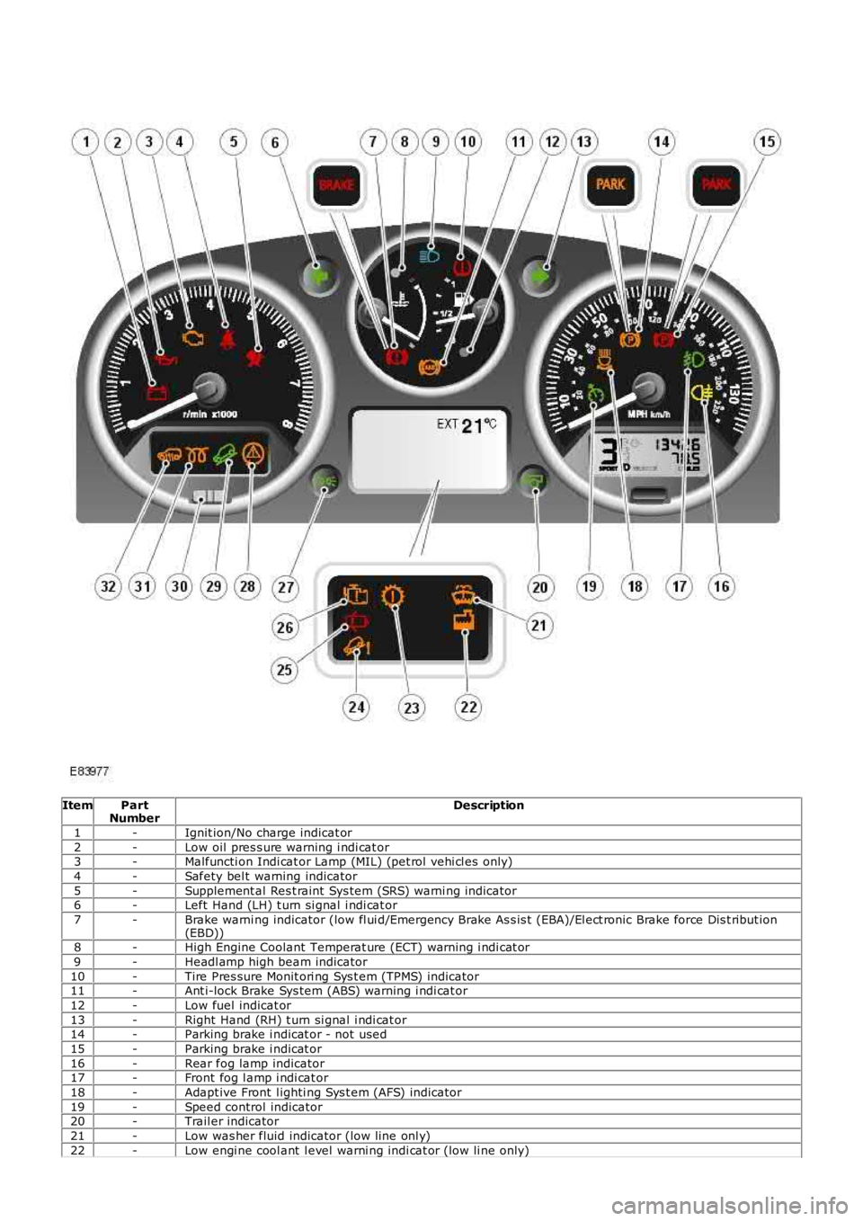
ItemPartNumberDescription
1-Ignit ion/No charge indicat or
2-Low oil pres s ure warning i ndi cat or3-Malfuncti on Indi cat or Lamp (MIL) (pet rol vehi cl es only)
4-Safety bel t warning indicator
5-Supplement al Res t raint Sys tem (SRS) warni ng indicator6-Left Hand (LH) t urn si gnal i ndi cat or
7-Brake warni ng indicator (low fl ui d/Emergency Brake As s is t (EBA)/El ect ronic Brake force Dis t ribut ion(EBD))8-High Engine Coolant Temperat ure (ECT) warning i ndi cat or
9-Headl amp high beam indicator
10-Tire Pres sure Monit ori ng Sys t em (TPMS) indicator11-Ant i-lock Brake Sys tem (ABS) warning i ndi cat or
12-Low fuel indicat or
13-Right Hand (RH) t urn si gnal i ndi cat or14-Parking brake i ndicat or - not used
15-Parking brake i ndicat or
16-Rear fog lamp indicator17-Front fog l amp i ndi cat or
18-Adapt ive Front l ighti ng Sys t em (AFS) indicator
19-Speed control indicator20-Trail er indicator
21-Low was her fluid indicator (low line onl y)
22-Low engi ne cool ant l evel warni ng indi cat or (low li ne only)
Page 1771 of 3229
Vehicle i n power mode 6 (all vehi cles except NAS vehicles )Vehicle i n power mode 6 for 75 s econds (NAS vehicl es onl y)Vehicle s peed is greater t han 6 mph (10 kph)Dri vers s afet y belt not s ecured in i ts buckleLarge pas senger det ect ed i n front pas s enger s eat wit h an uns ecured safety bel t.
The warni ng indicator wi ll flas h at a frequency of 2 Hz while accompani ed by a chime from the i nst rument clus ter for 10s econds. Thi s is foll owed by a 10 s econd period where the warning i ndicat or is permanent ly ill uminat ed and the s ounder i ss il ent . Thi s 10 s econd cycle wi ll be repeat ed for a maxi mum of 190 seconds or any of t he condit ions l is t ed above cease toexis t.
Supplemental Restraint System Warning Indicator
The Suppl ement al Rest rai nt Sys tem (SRS) warning i ndi cat or is i lluminated on recei pt of a medium s peed CAN bus si gnalfrom the CJB. The si gnal originat es in t he RCM whi ch monit ors t he condi ti on of the SRS and ill uminat es the red warni ngindicat or accordingly.
The SRS warni ng indicator i s il lumi nat ed by t he RCM for a 6 s econd bul b check when the vehicle firs t ent ers power mode 6.If a fault is detect ed wit h t he indicator, the ins trument cl us t er returns a medi um speed CAN bus s ignal vi a t he CJB to theRCM and a Diagnos t ic Troubl e Code (DTC) i s s tored in the RCM's memory. The mes s age 'SrS' wi ll als o be di spl ayed i n t heodometer.For addit ional informat ion, refer t o: Informat ion and Mes s age Cent er (413-08 Informat ion and Mes s age Cent er, Des cript ionand Operat ion).
Left and Right Hand Turn Signal Indicators
The green l eft and right hand turn s ignal i ndicat ors are i ll uminated on recei pt of medium speed CAN bus s i gnals from t heCJB. The CJB provi des a CAN bus s ignal wit h one of t he foll owing values :
0 - LH st eeri ng col umn mul ti -funct ion s wit ch in the central pos it ion1 - LH st eeri ng col umn mul ti -funct ion s wit ch in the LH turn posi ti on2 - LH st eeri ng col umn mul ti -funct ion s wit ch in the RH turn pos it ion3 - Hazard fl as hers reques t ed.
If the vehicle is i n power mode 6 t he ins trument cl ust er wil l fl as h the appropri ate turn s ignal i ndicat or if a medium speedCAN bus s ignal is recei ved wit h a value of 1 or 2. Medi um s peed CAN bus s ignals wi th a value of 3 wi ll acti vat e both theLH and RH turn s ignal i ndicat ors si mult aneous ly i rrespecti ve of power mode.
W hen acti vat ed, the l eft and right hand turn s ignal indicators wil l be accompanied by 'ti ck t ock' chimes from t he ins trumentclus ter s ounder.
Brake Warning Indicator
EBA and EBD warnings are trans mi tt ed t o t he CJB from t he ABS module over t he high s peed CAN bus . Thes e s ignals arerel ayed t o t he i ns t rument clus ter on t he medium s peed CAN bus and wil l act ivate the brake warning i ndicat or when t hevehi cl e i s in power mode 6. If an EBA warni ng is request ed, the i ndi cat or wil l ill uminat e in an amber color. If an EBDwarni ng is reques t ed, t he indi cat or will i ll uminate in a red color.
Low brake flui d level warnings are als o t rans mit t ed to the i nst rument clus t er from the CJB on the medi um s peed CAN bus .The s ignal origi nat es in the ABS modul e which recei ves a hardwired input from the brake flui d level s ens or. If a l ow brakefl uid warning i s reques ted, the indicator wil l il lumi nat e i n a red col or when the vehicle is i n power mode 6.
The brake warni ng indi cat or i s als o s ubject t o a 3 second bul b check when the vehicle firs t ent ers power mode 6. Theindicat or wi ll i lluminate in a amber color for 1.5 s econds t hen a red col or for 1.5 s econds .
High Eng ine Coolant Temperature Warning Ind icator
The red hi gh Engine Coolant Temperature (ECT) warning i ndi cat or is control led by the engine t emperat ure gage s oft ware(see above).
Headlamp High Beam Indicator
The blue headlamp hi gh beam i ndi cat or is i ll uminated on recei pt of a medium s peed CAN bus si gnal from the CJB. Thes ignal origi nat es in the l ight s wit ch module and i s t ransmit ted t o t he CJB over t he LIN bus. The i nst rument clus t er will onlyil lumi nat e t he headl amp high beam indicator when t he vehicle i s in power mode 6 and t he LH s teeri ng column mul ti -functi on s wit ch is moved t o t he high beam pos i ti on.
Tire Pressure Monitoring System Indicator
The Tire Pres s ure Moni tori ng Syst em (TPMS) indicator i s cont rol led by t he ins t rument clus ter on receipt of medium s peedCAN bus s ignals from t he CJB. The s ignal ori gi nates i n t he TPMS module. The indicator i s il lumi nat ed in an amber col or fora 3 second bulb check by the TPMS modul e when t he vehi cl e enters power mode 6. If t he indicator remains i lluminated orfl ashes after t he engi ne is st art ed or when dri vi ng, the TPMS has developed a faul t. The t ire pres s ures s houl d bemonit ored manuall y unti l the fault is recti fi ed.For addit ional informat ion, refer t o: W heels and Ti res (204-04 W heels and Tires , Des cript ion and Operat ion).
Anti-lock Brake System Warning Indicator
The Anti -l ock Brake Sys t em (ABS) warning i ndicat or is controll ed by the ABS module whi ch trans mi ts a high s peed CAN busmes s age to t he CJB. The CJB relays t he mes sage t o t he i ns t rument clus ter over the medi um s peed CAN bus . The warningindicat or i s il lumi nat ed i n an amber col or for 3 s econds for a bulb check by the ABS modul e when t he vehi cl e enters powermode 6. If the warning i ndi cat or remains ill uminat ed or ill uminat es when drivi ng, an ABS fault has occurred and t he ABSfuncti on wil l not be avai lable.
Duri ng the bul b check, if t he warni ng indicator comes on for 0.5 s econd, t hen goes off for 0.5 second and is then
Page 1772 of 3229
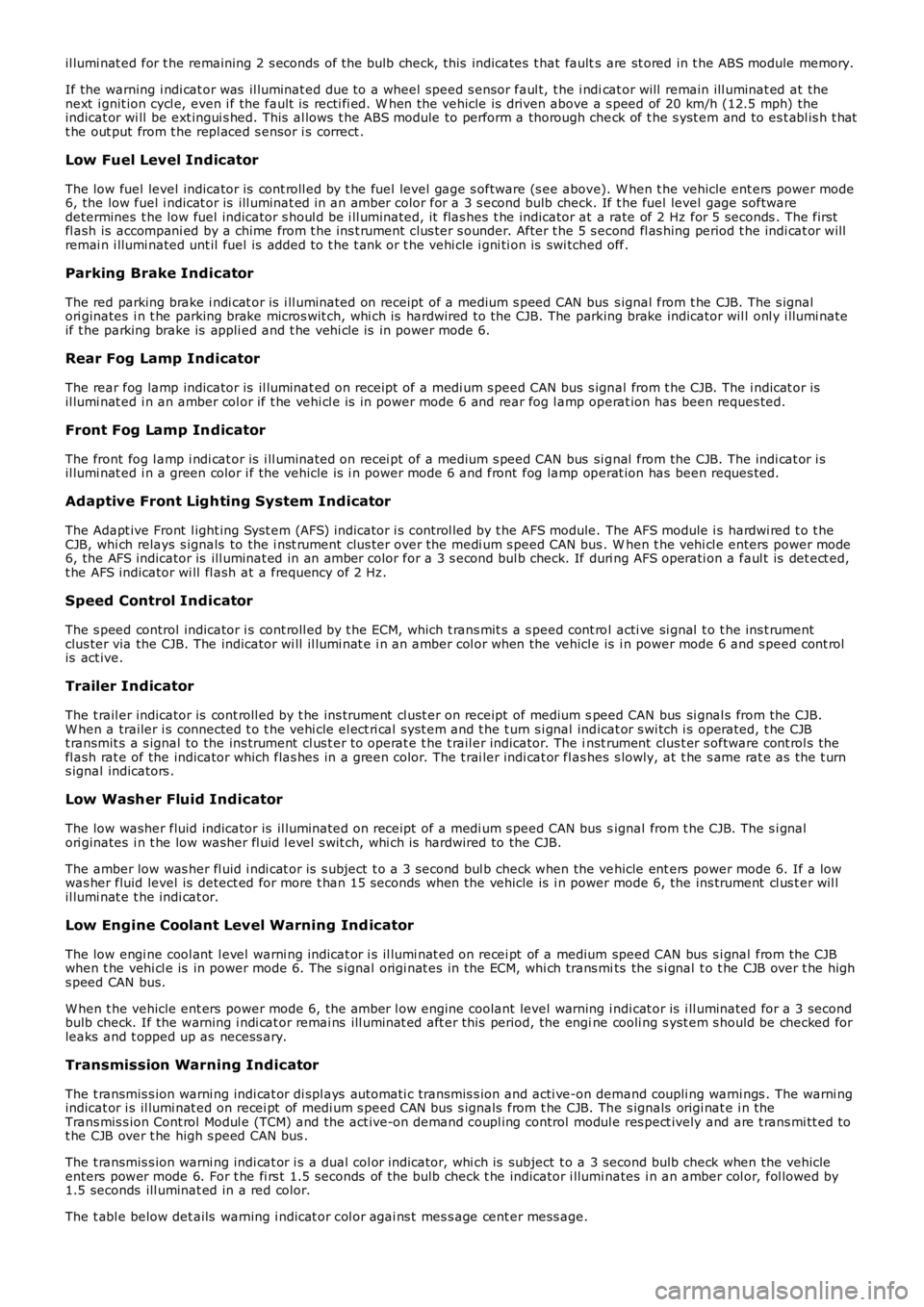
il lumi nat ed for t he remaining 2 s econds of the bulb check, this indicates t hat faults are st ored in t he ABS module memory.
If the warning i ndi cat or was il luminat ed due to a wheel speed s ensor faul t, t he i ndicat or will remain ill uminat ed at thenext i gnit ion cycl e, even i f the fault is recti fi ed. W hen the vehicle is driven above a s peed of 20 km/h (12.5 mph) theindicat or wi ll be ext ingui s hed. This al lows t he ABS module to perform a thorough check of t he s yst em and to es t abl is h t hatt he out put from t he repl aced s ensor i s correct .
Low Fuel Level Indicator
The low fuel level indicator is cont roll ed by t he fuel level gage s oftware (s ee above). W hen t he vehicle ent ers power mode6, the low fuel i ndicat or is ill uminat ed in an amber color for a 3 s econd bulb check. If t he fuel level gage softwaredetermines t he low fuel indicator s houl d be i ll uminated, it flas hes t he indicator at a rate of 2 Hz for 5 seconds . The firstfl ash is accompani ed by a chime from t he ins t rument clus ter s ounder. After t he 5 s econd fl as hing period t he indi cat or willremai n i llumi nated unt il fuel is added t o t he t ank or t he vehi cle i gni ti on is swi tched off.
Parking Brake Indicator
The red parking brake i ndi cat or is i ll uminated on receipt of a medium s peed CAN bus s ignal from t he CJB. The s ignalori ginates i n t he parking brake micros wit ch, whi ch is hardwired to the CJB. The parking brake indicator wil l onl y i llumi nateif t he parking brake is appli ed and t he vehi cl e is in power mode 6.
Rear Fog Lamp Indicator
The rear fog lamp indicator is il luminat ed on receipt of a medi um s peed CAN bus s ignal from t he CJB. The i ndicat or isil lumi nat ed i n an amber col or if t he vehi cl e is in power mode 6 and rear fog l amp operat ion has been reques ted.
Front Fog Lamp Indicator
The front fog l amp i ndi cat or is i ll uminated on recei pt of a medium s peed CAN bus si gnal from the CJB. The indi cat or i sil lumi nat ed i n a green color i f the vehicle is i n power mode 6 and front fog lamp operat ion has been reques ted.
Adaptive Front Lighting System Indicator
The Adapt ive Front l ight ing Syst em (AFS) indicator i s cont rol led by t he AFS module. The AFS module i s hardwi red t o t heCJB, whi ch relays s ignals to the i nst rument clus ter over the medi um s peed CAN bus . When t he vehi cl e enters power mode6, the AFS indicator is ill uminat ed in an amber color for a 3 s econd bul b check. If duri ng AFS operati on a faul t is det ect ed,t he AFS indicator wi ll fl ash at a frequency of 2 Hz.
Speed Control Indicator
The s peed control indicator i s cont roll ed by t he ECM, which t rans mit s a s peed cont rol acti ve si gnal t o t he ins t rumentclus ter via the CJB. The indicator wi ll il lumi nat e i n an amber col or when the vehicle is i n power mode 6 and s peed cont rolis act ive.
Trailer Indicator
The t rail er indicator is cont roll ed by t he ins trument cl ust er on receipt of medium speed CAN bus si gnal s from the CJB.W hen a trailer i s connected t o t he vehi cle el ect ri cal s ys t em and t he t urn s i gnal indicat or s wi tch i s operated, t he CJBt ransmit s a s ignal to the ins trument cl us t er to operat e t he t rail er indicator. The inst rument clus t er s oftware cont rol s thefl ash rat e of the indicator which flas hes in a green color. The t rai ler indi cat or flas hes s lowly, at t he s ame rat e as t he t urns ignal indicators .
Low Washer Fluid Indicator
The low washer fluid indicator is il luminat ed on receipt of a medi um s peed CAN bus signal from t he CJB. The s i gnalori ginates i n t he low washer fl uid l evel s wit ch, whi ch is hardwired to the CJB.
The amber low was her fl uid i ndi cat or is s ubject t o a 3 second bul b check when the vehicle ent ers power mode 6. If a lowwas her fluid level is detect ed for more t han 15 seconds when the vehicle is i n power mode 6, the ins trument cl us t er wil lil lumi nat e t he indi cat or.
Low Engine Coolant Level Warning Ind icator
The low engi ne cool ant l evel warni ng indicat or i s il lumi nat ed on recei pt of a medium speed CAN bus s i gnal from the CJBwhen t he vehi cl e is in power mode 6. The s ignal origi nat es in the ECM, whi ch trans mits the s i gnal t o t he CJB over t he highs peed CAN bus.
W hen t he vehicle ent ers power mode 6, the amber l ow engine coolant level warning i ndi cat or is i ll uminated for a 3 secondbulb check. If the warning i ndi cat or remai ns ill uminat ed aft er this period, the engine cooli ng s yst em s hould be checked forleaks and t opped up as necess ary.
Transmission Warning Indicator
The t ransmis s ion warni ng indi cat or di spl ays aut omati c transmis s ion and acti ve-on demand coupli ng warni ngs . The warni ngindicat or i s il lumi nat ed on recei pt of medi um s peed CAN bus s ignals from t he CJB. The s ignals origi nat e i n theTrans mis s ion Cont rol Modul e (TCM) and the act ive-on demand coupl ing control modul e res pect ively and are t rans mi tt ed tot he CJB over t he high s peed CAN bus .
The t ransmis s ion warni ng indi cat or i s a dual col or indicator, whi ch is subject t o a 3 second bulb check when the vehicleenters power mode 6. For t he fi rs t 1.5 seconds of the bulb check t he indicator i llumi nates i n an amber col or, fol lowed by1.5 seconds ill uminat ed in a red color.
The t abl e below det ails warning i ndicat or col or agai ns t mes s age cent er mess age.
Page 1776 of 3229
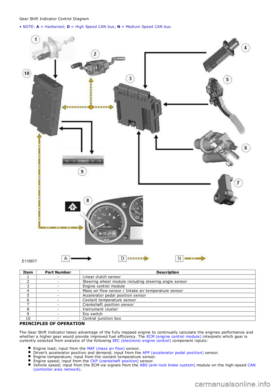
Gear Shi ft Indicat or Cont rol Di agram
• NOTE: A = Hardwi red; D = Hi gh Speed CAN bus ; N = Medium Speed CAN bus.
ItemPart NumberDescription1-Linear cl utch s ensor
2-Steering wheel modul e i ncludi ng st eeri ng angl e s ens or
3-Engi ne cont rol module4-Mas s air flow s ens or / Int ake ai r temperat ure sens or
5-Accelerator pedal pos it ion s ensor
6-Coolant temperat ure sens or7-Cranks haft pos i ti on s ens or
8-Ins t rument clus ter
9-Eco s wit ch10-Central junct ion box
PRINCIPLES OF OPERATION
The Gear Shi ft Indicat or takes advant age of the full y mapped engi ne to cont inually cal culat e t he engi nes performance andwhether a hi gher gear woul d provide improved fuel effi ci ency. The ECM (engi ne cont rol module) int erpret s whi ch gear iscurrent ly s elected from analys is of t he fol lowing EEC (elect ronic engine control) component i nput s:
Engi ne load; input from the MAF (mas s ai r flow) s ens or.Dri ver’s accelerat or pos it ion and demand; input from the APP (accelerator pedal pos it ion) s ens or.Engi ne t emperature; input from t he cool ant t emperat ure s ensor.Engi ne s peed; i nput from the CKP (cranks haft posi ti on) s ens or.Vehicle s peed; input from t he ECM via si gnal s from the ABS (anti -l ock brake s ys t em) module on t he high-speed CAN(controll er area network).
Page 1791 of 3229
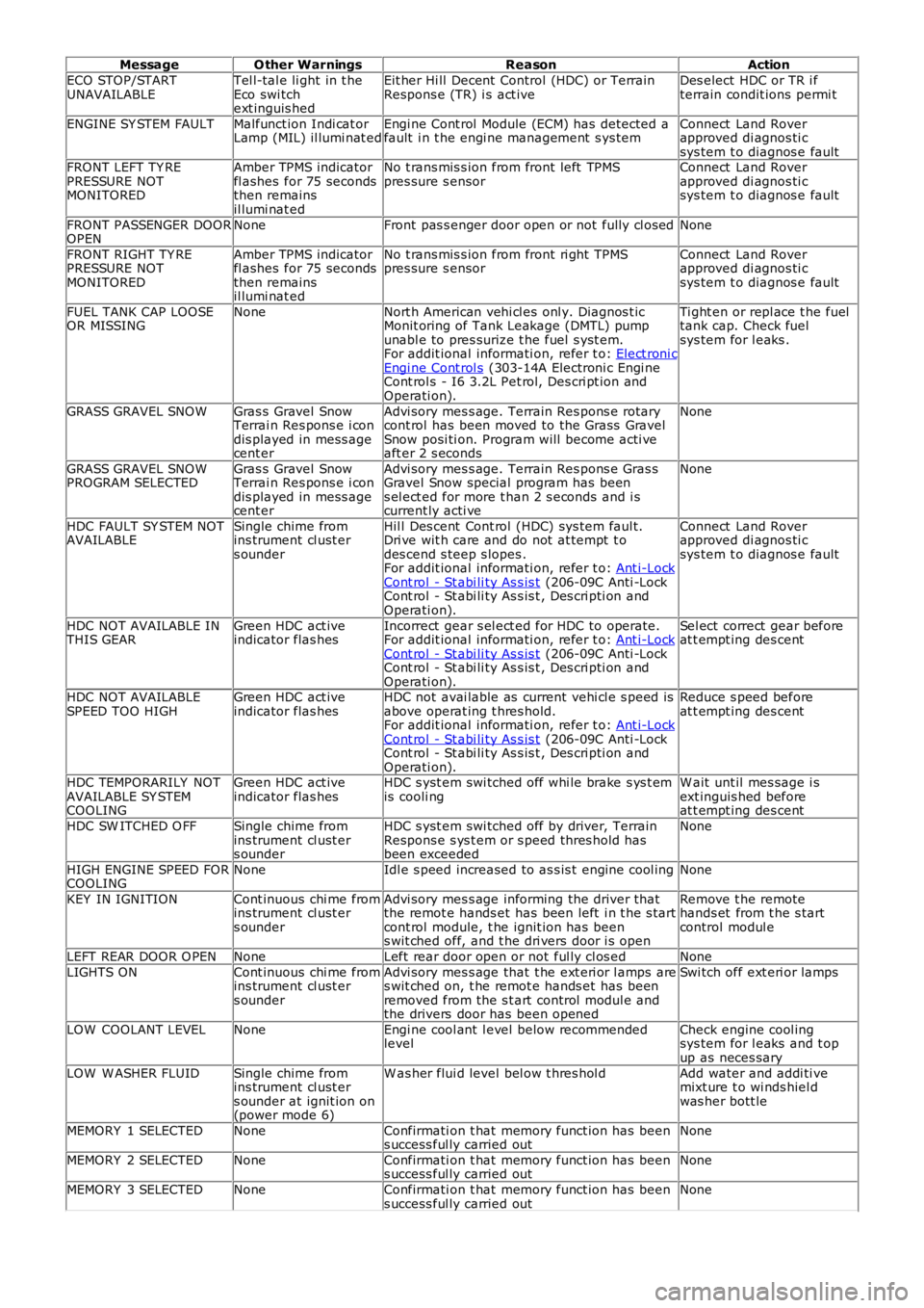
MessageO ther WarningsReasonAction
ECO STOP/STARTUNAVAILABLETel l-tal e li ght in t heEco swi tchext inguis hed
Eit her Hi ll Decent Control (HDC) or TerrainRespons e (TR) i s act iveDes elect HDC or TR i fterrain condit ions permi t
ENGINE SY STEM FAULTMalfunct ion Indi cat orLamp (MIL) il lumi nat edEngi ne Cont rol Module (ECM) has detected afault i n t he engi ne management s ys temConnect Land Roverapproved di agnos ti csys tem t o diagnos e faultFRONT LEFT TY REPRESSURE NOTMONITORED
Amber TPMS indicatorfl ashes for 75 secondsthen remainsil lumi nat ed
No t rans mis s ion from front left TPMSpres sure s ensorConnect Land Roverapproved di agnos ti csys tem t o diagnos e fault
FRONT PASSENGER DOOROPENNoneFront pas s enger door open or not fully cl osedNone
FRONT RIGHT TY REPRESSURE NOTMONITORED
Amber TPMS indicatorfl ashes for 75 secondsthen remainsil lumi nat ed
No t rans mis s ion from front ri ght TPMSpres sure s ensorConnect Land Roverapproved di agnos ti csys tem t o diagnos e fault
FUEL TANK CAP LOOSEOR MISSINGNoneNort h American vehi cl es onl y. Diagnos t icMonit oring of Tank Leakage (DMTL) pumpunabl e to pres surize t he fuel s yst em.For addit ional informati on, refer t o: Elect roni cEngi ne Cont rol s (303-14A Electroni c Engi neCont rol s - I6 3.2L Pet rol, Des cri pt ion andOperati on).
Ti ght en or repl ace t he fueltank cap. Check fuelsys tem for l eaks .
GRASS GRAVEL SNOWGras s Gravel SnowTerrai n Res pons e i condis played in mess agecent er
Advi sory mes s age. Terrain Res pons e rotarycont rol has been moved to the Grass GravelSnow posi ti on. Program will become acti veaft er 2 s econds
None
GRASS GRAVEL SNOWPROGRAM SELECTEDGras s Gravel SnowTerrai n Res pons e i condis played in mess agecent er
Advi sory mes s age. Terrain Res pons e Gras sGravel Snow special program has beens el ect ed for more t han 2 s econds and i scurrent ly acti ve
None
HDC FAULT SY STEM NOTAVAILABLESingle chime fromins trument cl ust ers ounder
Hil l Des cent Cont rol (HDC) sys tem faul t.Dri ve wit h care and do not at tempt t odes cend s teep s lopes .For addit ional informati on, refer t o: Ant i-LockCont rol - St abi li ty As s is t (206-09C Anti -LockCont rol - St abi li ty As s is t , Des cri pti on andOperati on).
Connect Land Roverapproved di agnos ti csys tem t o diagnos e fault
HDC NOT AVAILABLE INTHIS GEARGreen HDC act iveindicator flas hesIncorrect gear s el ect ed for HDC to operate.For addit ional informati on, refer t o: Ant i-LockCont rol - St abi li ty As s is t (206-09C Anti -LockCont rol - St abi li ty As s is t , Des cri pti on andOperati on).
Sel ect correct gear beforeat t empt ing des cent
HDC NOT AVAILABLESPEED TOO HIGHGreen HDC act iveindicator flas hesHDC not avai lable as current vehi cl e s peed isabove operat ing t hres hold.For addit ional informati on, refer t o: Ant i-LockCont rol - St abi li ty As s is t (206-09C Anti -LockCont rol - St abi li ty As s is t , Des cri pti on andOperati on).
Reduce s peed beforeat t empt ing des cent
HDC TEMPORARILY NOTAVAILABLE SY STEMCOOLING
Green HDC act iveindicator flas hesHDC s yst em swi tched off whi le brake s ys t emis cooli ngW ait unt il mes sage i sext inguis hed beforeat t empt ing des cent
HDC SW ITCHED O FFSingle chime fromins trument cl ust ers ounder
HDC s yst em swi tched off by driver, TerrainRespons e s ys t em or s peed thres hold hasbeen exceeded
None
HIGH ENGINE SPEED FORCOOLINGNoneIdl e s peed increased to as s is t engine cool ingNone
KEY IN IGNITIONCont inuous chi me fromins trument cl ust ers ounder
Advi sory mes s age informing the driver thatthe remot e hands et has been left i n t he s tartcont rol module, t he ignit ion has beens wit ched off, and t he dri vers door i s open
Remove t he remotehands et from t he s tartcontrol modul e
LEFT REAR DOOR O PENNoneLeft rear door open or not ful ly cl os edNone
LIGHTS ONCont inuous chi me fromins trument cl ust ers ounder
Advi sory mes s age that t he ext eri or l amps ares wit ched on, t he remot e hands et has beenremoved from the s t art control modul e andthe drivers door has been opened
Swi tch off ext eri or lamps
LOW COOLANT LEVELNoneEngi ne cool ant l evel below recommendedlevelCheck engine cool ingsys tem for l eaks and t opup as neces sary
LOW W ASHER FLUIDSingle chime fromins trument cl ust ers ounder at ignit ion on(power mode 6)
W as her flui d level bel ow t hres hol dAdd water and addi ti vemixt ure t o wi nds hiel dwas her bott le
MEMORY 1 SELECTEDNoneConfirmati on t hat memory funct ion has beens uccess ful ly carried outNone
MEMORY 2 SELECTEDNoneConfirmati on t hat memory funct ion has beens uccess ful ly carried outNone
MEMORY 3 SELECTEDNoneConfirmati on t hat memory funct ion has beens uccess ful ly carried outNone
Page 2560 of 3229

Publ is hed: 11-May-2011
Front End Sheet Metal Repairs - Fender Apron Panel
Removal and Installation
Removal
• NOTE: The fender apron panel is serviced as a separate weld-on panel. It is an assembly of the fender apron panel
reinforcement, fender apron lower panel and fender apron panel front extension.
• NOTE: The panel is serviced less its weld studs
1. The fender apron panel is replaced in conjunction with:
Front bumper cover
Hood lat ch panel
Both front fenders
Fender apron upper panel
2. Fo r a d d i t i o na l i nf o rma t i o n re l a t i ng t o t hi s re p a i r p ro ce d ure
please see the following:
Fo r a d d i t i o na l i nf o rma t i o n, re f e r t o : Body and Frame
(501-26
Body Repairs - Vehicle Specific Information and Tolerance
Checks, Description and Operation) /
St a nd a rd W o rks ho p P ra ct i ce s
(100-00 Ge ne ra l I nf o rma t i o n,
Description and Operation).
3. Remove the fender apron upper panel.
Fo r a d d i t i o na l i nf o rma t i o n, re f e r t o : Fender Apron Upper Panel
(501-27 Front End Sheet Met al Re pai rs , Removal and
Installation).
4. L H Si d e : Re mo ve t he a i r cl e a ne r.
Fo r a d d i t i o na l i nf o rma t i o n, re f e r t o : Air Cleaner
(303-12A
I nt a ke A i r Di s t ri b ut i o n a nd Fi l t e ri ng - I 6 3. 2L P e t ro l , Re mo va l
and Installation).
5. LH Side: Remove the air intake pipe.
6. LH Side: Remove the bat tery t ray.
Fo r a d d i t i o na l i nf o rma t i o n, re f e r t o : Battery Tray
(414-01
Battery, Mounting and Cables, Removal and Installation).
7. LH Side: Remove the engine lower support insulator.
Fo r a d d i t i o na l i nf o rma t i o n, re f e r t o : Engine Lower Support
Insulator (303-01A Engi ne - I6 3.2L Pet rol, Removal and
Installation).
8. LH Side: Release the battery junction box and position aside.
9. RH Side: Drain the cooling system.
Fo r a d d i t i o na l i nf o rma t i o n, re f e r t o : Cooling Sys tem Draining,
Filling and Bleeding (303-03A Engine Cooling - I6 3.2L Petrol,
General Procedures ).
10. RH Side: Evacuate the A/C system.
Fo r a d d i t i o na l i nf o rma t i o n, re f e r t o : Air Conditioning (A/C)
System Recovery, Evacuation and Charging (412-00 Cl i mat e
Co nt ro l Sys t e m - Ge ne ra l I nf o rma t i o n, Ge ne ra l P ro ce d ure s ).
11. RH Si d e : Re mo ve t he p o we r s t e e ri ng re s e rvo i r.
Fo r a d d i t i o na l i nf o rma t i o n, re f e r t o : P o we r St e e ri ng Fl ui d
Res ervoi r (211-02 Power St eeri ng, Removal and Ins t al lat i on).
12. RH Side: Release the coolant expansion tank and position
aside.
13. RH Side: Remove the engine mounting bracket.
Fo r a d d i t i o na l i nf o rma t i o n, re f e r t o : Engine Mount RH
(303-01A
Engine - I6 3.2L Petrol, Removal and Installation).
14. RH Side: Remove the windshield washer reservoir.
Fo r a d d i t i o na l i nf o rma t i o n, re f e r t o : Windshield Washer
Res ervoi r (501-16 W i pers and W as hers , Removal and
Installation).
15. RH Side: Remove the fender apron A/C pipes.
16. Remove the shock absorber and spring assembly.
Fo r a d d i t i o na l i nf o rma t i o n, re f e r t o : Sho ck A b s o rb e r a nd Sp ri ng
Assembly (204-01 Front Sus pens i on, Removal and
Installation).
17. Release and lay aside the wiring harness.