2006 LAND ROVER FRELANDER 2 engine coolant
[x] Cancel search: engine coolantPage 978 of 3229
Publi s hed: 11-May-2011
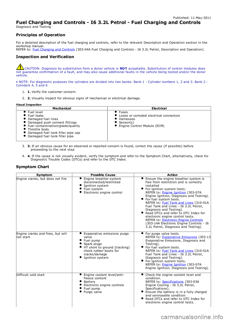
Fuel Charging and Controls - I6 3.2L Petrol - Fuel Charging and Controls
Diagnosi s and Tes ti ng
Principles of Operation
For a detail ed descripti on of the fuel chargi ng and cont rol s, refer t o the relevant Descri pti on and Operat ion s ect ion in t heworks hop manual .REFER to: Fuel Chargi ng and Controls (303-04A Fuel Chargi ng and Cont rol s - I6 3.2L Pet rol, Des cri pt ion and Operati on).
Inspection and Verification
CAUTION: Di agnos is by s ubs ti tut ion from a donor vehicle is NO T acceptabl e. Subs ti tut ion of cont rol modules doesnot guarant ee confirmat ion of a faul t, and may als o caus e addit ional fault s i n t he vehi cl e being t est ed and/or t he donorvehi cl e.
• NOTE: For di agnos t ic purpos es the cyli nders are divided i nt o t wo banks: Bank 1 - Cyl inder numbers 1, 2 and 3. Bank 2 -Cylinders 4, 5 and 6
1. Verify t he cus t omer concern.1.
2. Vis ually ins pect for obvious s igns of mechani cal or electrical damage.2.
Visual Inspection
MechanicalElectricalFuel l evelFuel l eaksDamaged fuel l inesDamaged push connect fit t ingsFuel contami nati on/grade/quali tyThrot tl e bodyDamaged fuel t ank fi ller pipe capDamaged fuel t ank fi ller pipe
FusesLoos e or corroded elect rical connect orsHarnes s esSensor(s )Engine Control Modul e (ECM)
3. If an obvious cause for an obs erved or report ed concern is found, correct t he caus e (if pos s ible) beforeproceeding t o t he next s t ep3.
4. If t he caus e is not vis ually evi dent , verify t he sympt om and refer t o t he Sympt om Chart, al ternat ively, check forDi agnos ti c Trouble Codes (DTCs) and refer t o t he DTC Index.4.
Symptom Chart
SymptomPossible CauseAction
Engine cranks , but does not fi reEngine breat her s ys temdis connected/res trictedIgni ti on s ys t emFuel s ys temElectronic engine control
Ens ure the engine breat her sys tem isfree from rest ri ct ion and is correct lyi nst all edFor igni ti on sys t em t est s .REFER t o: Engi ne Ignit ion (303-07AEngine Ignit ion, Diagnosi s and Test ing).For fuel s yst em tes ts .REFER t o: Fuel Tank and Lines (310-01AFuel Tank and Li nes - I6 3.2L Petrol,Di agnos is and Tes t ing).Read DTCs and refer t o DTC Index forel ect ronic engine cont rol tes t s.REFER t o: Elect roni c Engi ne Cont rol s(303-14A Elect ronic Engine Cont rols - I63.2L Petrol , Diagnosi s and Test ing).
Engine cranks and fires , but wil lnot s tartEvaporati ve emis s ions purgevalveFuel pumpSpark pl ugsHT s hort t o ground (t racki ng)check rubber boots forcracks/damageIgni ti on s ys t em
For purge valve t es ts .REFER t o: Evaporat ive Emi ss i ons (303-13Evaporati ve Emis s ions , Diagnosi s andTes ti ng).For fuel s yst em tes ts .REFER t o: Fuel Tank and Lines (310-01AFuel Tank and Li nes - I6 3.2L Petrol,Di agnos is and Tes t ing).For igni ti on sys t em t est s .REFER t o: Engi ne Ignit ion (303-07AEngine Ignit ion, Diagnosi s and Test ing).
Di fficul t col d s t artEngine coolant level/ant i-freeze cont entBatt eryElectronic engine controlsFuel pumpPurge valve
Check t he engi ne cool ant l evel andcondit ion.REFER t o: Specificati ons (303-03AEngine Cool ing - I6 3.2L Pet rol ,Specificat ions ).Ens ure the bat tery is i n a full y chargedand s ervi ceable condit ionRead DTCs and refer t o DTC Index forel ect ronic engine cont rol tes t s.
Page 1103 of 3229
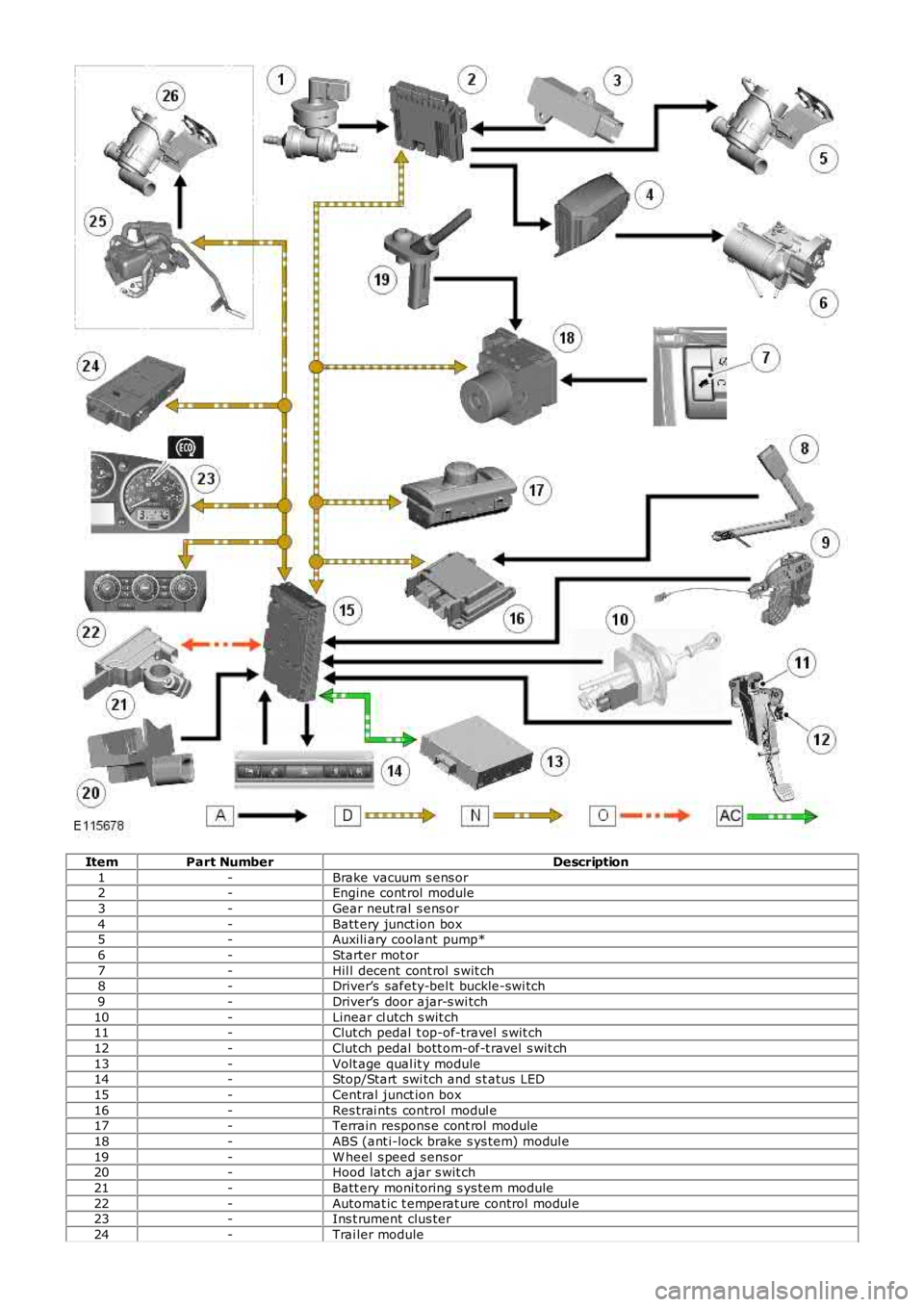
ItemPart NumberDescription
1-Brake vacuum s ens or2-Engine cont rol module
3-Gear neut ral s ens or
4-Batt ery junct ion box5-Auxili ary coolant pump*
6-Starter mot or
7-Hil l decent cont rol s wit ch8-Driver’s safety-bel t buckle-swi tch
9-Driver’s door ajar-s wi tch
10-Linear cl utch s wit ch11-Clut ch pedal t op-of-travel s wit ch
12-Clut ch pedal bott om-of-t ravel s wit ch
13-Volt age qual it y module14-Stop/Start swi tch and s t atus LED
15-Central junct ion box
16-Res trai nts control modul e17-Terrain respons e cont rol module
18-ABS (ant i-lock brake s ys tem) modul e
19-W heel s peed s ens or20-Hood lat ch ajar s wit ch
21-Batt ery moni toring s ys tem module
22-Automat ic t emperat ure control modul e23-Ins t rument clus ter
24-Trai ler module
Page 1104 of 3229
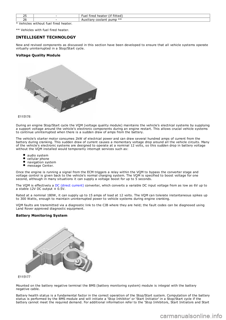
25-Fuel fired heat er (i f fi tt ed)
26-Auxili ary coolant pump **
* Vehicles wit hout fuel fired heat er.
** Vehicles wi th fuel fi red heater.
INTELLIGENT TECHNOLOGY
New and revi s ed components as di s cus s ed in this secti on have been developed t o ensure t hat al l vehicl e s ys t ems operatevirtuall y uninterrupt ed in a Stop/St art cycl e.
Voltage Quality Module
Duri ng an engine St op/Start cycle t he VQM (volt age qual it y module) mai ntains t he vehicle’s el ect ri cal s yst ems by s upplyinga s upport volt age around the vehicle's electroni c components during an engine res tart. This al lows crucial vehicle s ys temst o cont inue unint errupt ed when t here i s a s udden draw of amps from the bat tery.
The vehi cl e’s s t art er mot or cons umes 2kW of el ect ri cal power and can draw s everal hundred amps of current from thebatt ery during cranking. Thi s s udden draw of current causes a momentary volt age drop around al l t he vehicle ci rcuit s. Manyof the vehicle's electroni c s ys t ems are des i gned t o operat e at a nomi nal 12 volt s , so thi s s udden drop in bat tery volt agewit hout the VQM ins t al led woul d temporaril y i nt errupt servi ces such as :
audi o s yst emcel lul ar phonenavi gat ion sys temmes s age Cent er.
Once the engi ne is runni ng a s ignal from t he ECM triggers a relay wit hi n t he VQM t o bypass the converter s t age andvolt age control is gi ven back t o t he vehi cl e's normal charging sys tem. The VQM is specified t o boost vol tage for ones econd, alt hough i n many s it uati ons i t can s upply a volt age boos t for up t o 5 seconds .
The VQM is effecti vel y a DC (direct current) converter, which convert s a variable DC input vol tage from as l ow as 6V up t oa s t abl e 12V DC out put ± 0.5V.
Rated at a nominal 180W , it can s uppl y up t o 15 amps of load at 12 vol ts . The VQM can t olerat e i ns t ant aneous s pikes upt o 300 W at ts , enough to maintai n uninterrupt ed power t o vehicle s ys tems during engine cranking.
VQM fault s are trans mi tt ed via a diagnost ic l ink t o t he CJB where they are hel d; the fault codes can be di agnos ed us ingLand Rover approved diagnos t ic equipment .
Battery Monitoring System
Mounted on t he batt ery negat ive t ermi nal t he BMS (batt ery moni toring s yst em) module is i ntegral wi th t he batt erynegat ive cable.
Batt ery healt h s t at us i s a fundamental fact or in t he correct operat ion of t he Stop/St art s ys tem. Computat ion of t he batt erys tat us is performed by t he BMS module and will i nit iate a ‘St op Inhi bit or’ or ‘Start Ini ti at or’ i n a St op/Start cycle if t hebatt ery cannot meet t he requi red demand. For addit ional informati on refer to the ‘Stop Inhi bit ors , Start Init iat ors and St art
Page 1107 of 3229
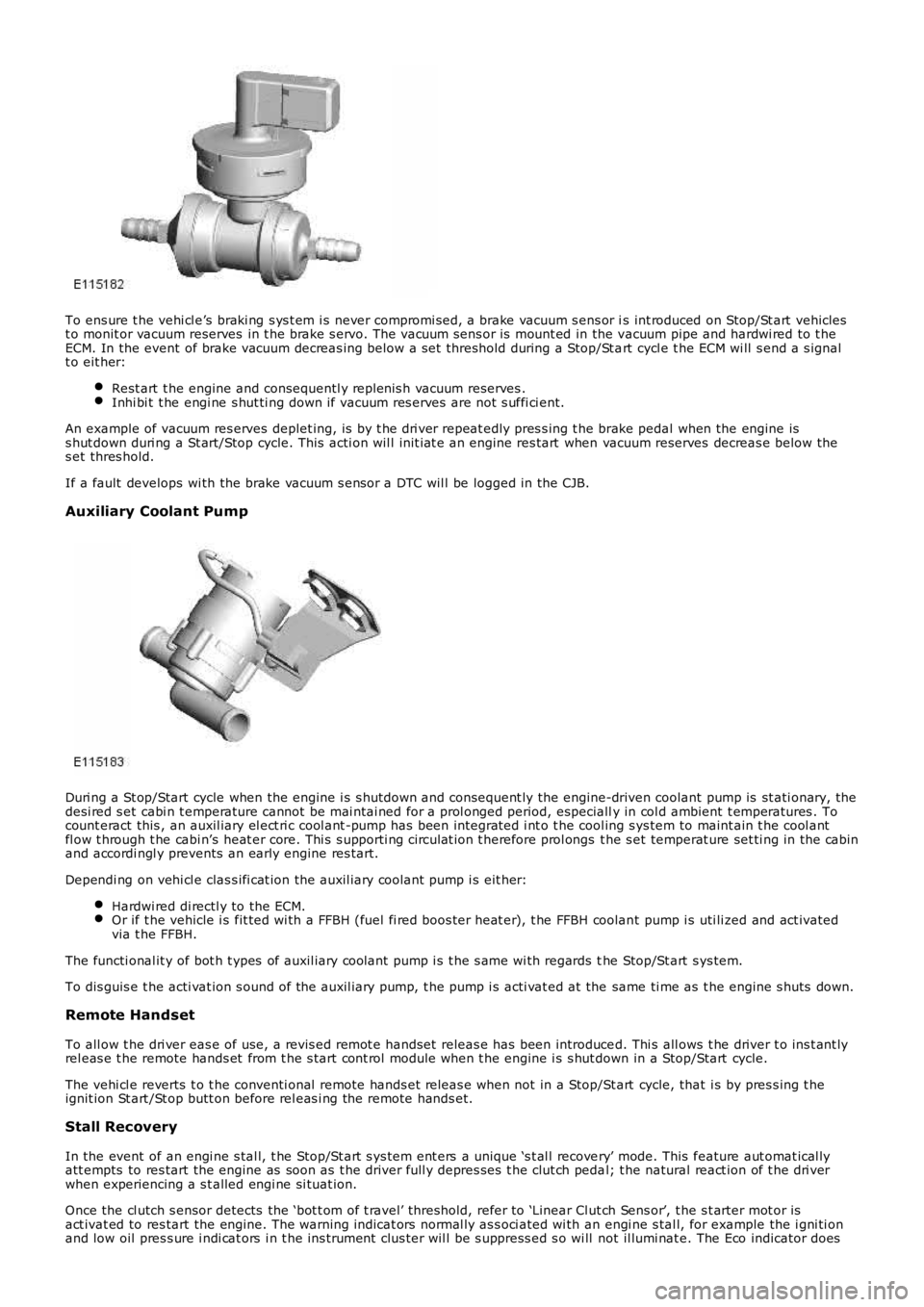
To ens ure t he vehi cl e’s braki ng s ys t em i s never compromi sed, a brake vacuum s ens or is int roduced on Stop/St art vehiclest o monit or vacuum reserves in t he brake s ervo. The vacuum sens or is mount ed in the vacuum pipe and hardwi red to t heECM. In the event of brake vacuum decreas ing below a s et threshold during a Stop/St art cycl e t he ECM wi ll s end a s ignalt o eit her:
Rest art t he engine and consequentl y replenis h vacuum reserves .Inhi bi t t he engi ne s hut ti ng down if vacuum res erves are not s uffi ci ent.
An example of vacuum res erves deplet ing, is by t he dri ver repeat edly pres s ing t he brake pedal when the engine iss hut down duri ng a St art/Stop cycle. This acti on wil l init iat e an engine res tart when vacuum reserves decreas e below thes et thres hold.
If a fault develops wi th the brake vacuum s ensor a DTC wil l be logged in the CJB.
Auxiliary Coolant Pump
Duri ng a St op/Start cycle when the engine i s s hutdown and consequent ly the engine-driven coolant pump is st ati onary, thedesi red s et cabi n t emperature cannot be mai ntai ned for a prol onged period, especially in col d ambient t emperatures . Tocount eract this , an auxil iary el ect ri c cool ant -pump has been integrat ed i nt o t he cool ing s ys tem to maint ain t he cool antfl ow t hrough t he cabi n’s heat er core. Thi s s upporti ng ci rculat ion t herefore prol ongs t he s et temperat ure set ti ng in the cabinand accordi ngl y prevents an early engine res tart.
Dependi ng on vehi cl e clas s ifi cat ion the auxil iary coolant pump i s eit her:
Hardwi red di rectl y to the ECM.Or if t he vehicle i s fit ted wi th a FFBH (fuel fi red boos ter heat er), t he FFBH coolant pump i s uti li zed and act ivatedvia t he FFBH.
The functi onal it y of bot h t ypes of auxil iary coolant pump i s t he s ame wi th regards the Stop/St art s ys tem.
To dis guis e t he acti vat ion s ound of the auxil iary pump, t he pump i s acti vat ed at the same ti me as t he engine s huts down.
Remote Handset
To all ow t he dri ver eas e of use, a revis ed remot e handset releas e has been introduced. Thi s all ows t he driver t o ins t ant lyrel eas e t he remote hands et from t he s tart cont rol module when t he engine i s s hut down in a Stop/Start cycle.
The vehi cl e reverts t o t he conventi onal remote hands et releas e when not in a Stop/Start cycle, that i s by pres s ing t heignit ion St art /St op butt on before rel eas i ng the remote hands et.
Stall Recovery
In the event of an engi ne s tal l, t he Stop/St art s ys tem ent ers a unique ‘s t al l recovery’ mode. This feature aut omat ical lyatt empts to res tart the engine as soon as t he driver full y depres ses t he clut ch pedal; t he natural react ion of t he dri verwhen experiencing a s t alled engi ne si tuat ion.
Once the cl utch s ensor detects the ‘bot t om of t ravel’ threshold, refer to ‘Linear Clut ch Sens or’, t he s t arter mot or isact ivat ed to res tart the engine. The warni ng indicat ors normal ly as s oci ated wi th an engi ne s tal l, for example the i gni ti onand low oil pres s ure i ndi cat ors i n t he ins t rument clus ter wil l be s uppress ed s o wi ll not il lumi nat e. The Eco indicator does
Page 1108 of 3229
however remain i ll uminated.
A ‘st all recovery’ event is the onl y s tat e when t he Stop/St art s yst em wil l permit t he engine t o be s t art ed when thet ransmis s ion i s in gear; hence t he requirement for t he cl utch pedal to be full y depres sed. If the s t all recovery fai ls and t heengi ne does not res tart, t he dri ver wi ll be reques ted vi a t he Mess age Center t o ‘s elect neutral ’ to at t empt anot her rest art .
If the engine does not res t art aft er thi s request t he ‘st all recovery’ mode wil l ti me-out and deact ivate. At t his point t he‘Eco’ i con in t he i ns t rument panel wi ll exti ngui sh and the light s usual ly as s ociat ed wi th an engi ne st all wi ll il lumi nat e. As ares ult t he dri ver will be requi red to perform a convent ional engi ne res tart.
Alt hough st all recovery i s a feat ure of t he St op/Start sys t em i t is pos si ble for it t o acti vat e i ndependent ly from t heStop/St art parameters . For exampl e:
If the St op/Start s ys t em has been deact ivated by the driver st all recovery wi ll s ti ll funct ion.Stal l recovery wil l act ivate at ambi ent temperat ures as l ow as (minus ) - 2°C, whereas the St op/Syst em operat ingt emperature threshold is above 4°C.Different t o t he operat ion of t he Stop/St art s yst em, s tal l recovery wil l st il l functi on when the vehicle is t owing;refer to the ‘Trail er Towi ng’ s ect ion.
• NOTE: As t he neces s ary cri teria will not have been sat is fi ed when t he vehi cl e i s at the beginning of a journey s t allrecovery wi ll not functi on. For exampl e, if t he vehi cl e s tal ls when l eavi ng the garage or driveway a convent ional engineres t art wi ll be required.
Trailer Towing
The Stop/St art s ys tem wil l aut omati cal ly di sabl e when t rail er light s are det ect ed by t he CJB via s ignals from t he t rail ermodule, t hi s informat ion i s t hen trans mi tt ed t o t he ECM. It i s not pos s ibl e for t he s ys t em t o det ect when a trai ler powerplug i s ins ert ed i n the vehicl e’s t owi ng s ocket s o it us es operat ion of t he trail er l ights as it s indi cat or.
The t rail er towing sys tem inhi bi ts St op/St art as i t is pos s ible that trail er power requirements could interfere wit h t heoperati on of the bat tery monit ori ng s ys t em. In parti cul ar, a t rai ler batt ery could revers e t he feed current t o t he vehicleduri ng an engi ne cranking event , t hi s coul d pos si bly:
Confus e t he bat t ery monit ori ng s ys t em i nto det ect ing an unreal is t ically smal l current at engi ne cranking.Rupture the fus e as sociat ed wit h t he t rail er modul e.
Climate Control System
• NOTE: The ‘ECON’ butt on has been renamed ‘A/C’ to prevent confus ion wi th the St op/St art s yst em ‘Eco’ s wit ch.
A number of changes have been made to the l ogi c and operati on of climat e control system, wit hi n a St op/St art cycle to:
maint ain occupant comfortprevent winds hi eld mis ti ngcons erve bat tery power.
This has been achi eved by the ATC (automat ic t emperat ure control) module monit oring and varyi ng, as necess ary variousclimate control funct ions wi thi n a St op/Start cycle.
In s ome circums t ances t he ATC has t he capabil it y to inhibit an engi ne s hut down or init iat e an engine rest art wit hi n aStop/St art cycle. Thi s i s achi eved by t he ATC module communi cat ing wit h t he CJB on the medi um s peed CAN. The variousoverri de functi ons the ATC has in a St op/St art cycl e are di s cus s ed bel ow:
Coolant temperat ure
The ATC module wil l i nhibit an engine shut down or i nit iat e an engine res t art wi thi n a St op/Start cycle if t he coolantt emperature fal ls below the calculat ed t hreshol d to s upport t he cabin t emperat ure s et by t he vehi cl e occupant s .
W i nds hiel d demis t ing
The variant of cli mate control fi tt ed t o the vehicl e influences t he s oft ware changes that have been made. For exampl e, thebase cl imat e-control s ys tem does not have a humi dit y s ens or, as us ed on a highline sys tem t o ini ti at e a winds hi elddemis t . Therefore, a calculat ion for demis ti ng the winds hi eld i s made us ing t he s ignals from t he rai n s ens or and ambientt emperature s ens or. Us i ng the probabi lit y t hat windshi eld mis ti ng wil l occur if i t is raining and t he ambi ent t emperat ure i scool , the ATC wil l presume a wi nds hiel d demis t is required and s tart the engine when i n a St op/St art cycl e.
Evaporat or temperat ure the main cause of windshi eld mis ti ng is al s o monit ored and t he high-line cl imat e cont rol s yst emwil l periodicall y cool t he evaporat or as neces s ary t o reduce mi s ti ng during a Stop/St art cycl e. The sys tem operates thewinds hield demis t s hut ter and i f the evaporator i s wet t he shut ter wi ll remai n clos ed for a few seconds after an engineres t art unti l the vapor is di ss ipat ed.
If the driver sel ect s eit her ‘programmed defros t ’ or t he ‘wi ndshi el d heater’ i t is as s umed t hat a qui ck demis t of thewinds hield is requi red. Therefore, t he ATC vi a the CJB will ei ther: i nhibit an engine shut down or i nit iat e an engine res t art .
Heater fan speed
Duri ng an engine s hutdown t he ATC monit ors cabin temperat ure and maint ai ns the fan speed at a l evel that wi ll cons erve,for as l ong as poss ibl e t he heat i n t he core of t he cabi n heat er. If the driver s elect s a hi gher fan s peed and the heatcannot be mai ntained i n t he heat er core, the engine will rest art .
Heated rear window and heated s eats
If the heated rear window or heated s eats are acti ve or act ivated during an engine shut down event t he power out put oft he relevant s ys t em wi ll be i nt errupted unt il the engi ne is rest art ed. The tell -t ale light i n t he relevant s wit ch wil lil lumi nat e t o i ndi cat e t he s ys t em i s act ive even t hough the s ys tem is recei vi ng no power. This feature is us ed t o conservebatt ery power.
Page 1115 of 3229
Publi s hed: 11-May-2011
Engine Ignition - Engine Ignition
Diagnosi s and Tes ti ng
Principles of Operation
For a detail ed descripti on of the ignit ion s yst em, refer to the relevant Des cri pti on and Operati on s ect ion i n t he works hopmanual.REFER to: Engine Ignit ion (303-07A Engi ne Igni ti on, Des cript ion and O perati on).
Inspection and Verification
CAUTION: Di agnos is by s ubs ti tut ion from a donor vehicle is NO T acceptabl e. Subs ti tut ion of cont rol modules doesnot guarant ee confirmat ion of a faul t, and may als o caus e addit ional fault s i n t he vehi cl e being t est ed and/or t he donorvehi cl e.
1. Verify t he cus t omer concern.1.
2. Vis ually ins pect for obvious s igns of mechani cal or electrical damage.2.
Visual InspectionMechanicalElectrical
Engine oil l evelCooli ng sys t em cool ant levelFuel l evelFuel contami nati on/grade/quali ty
Fus esW iring harnes sLoos e or corroded electrical connect orsIgnit ion coil sSens or(s)Engine Cont rol Modul e (ECM)
3. If an obvious cause for an obs erved or report ed concern is found, correct t he caus e (if pos s ible) beforeproceeding t o t he next s t ep3.
4. If t he caus e is not vis ually evi dent , verify t he sympt om and refer t o t he Sympt om Chart, al ternat ively, check forDi agnos ti c Trouble Codes (DTCs) and refer t o t he DTC Index.4.
Symptom Chart
SymptomPossible CauseActionEngine cranks , but doesnot fi reEngine breat her sys temdis connected/res trict edEngine i gni ti on s ys t emFuel sys temElect ronic engine controls
Ens ure the engine breat her sys t em i s free fromres tricti on and is correctl y ins tal ledRead DTCs and refer t o DTC Index in t his s ecti on forengine ignit ion s ys tem tes tsFor fuel s yst em tes ts .REFER t o: Fuel Tank and Lines (310-01A Fuel Tank andLi nes - I6 3.2L Petrol, Diagnos is and Tes ti ng).Read DTCs and refer t o t he DTC Index for elect roni cengine cont rols .REFER t o: Electroni c Engi ne Control s (303-14AEl ect ronic Engi ne Cont rol s - I6 3.2L Pet rol, Di agnos isand Tes t ing).
Engine cranks and fires ,but wil l not s t artEvaporati ve emis s ionspurge val veFuel pumpSpark pl ugsHT short to ground(tracki ng) check rubberboots for cracks /damageIgni ti on coil fai lure(s )
For purge valve tes ts .REFER t o: Evaporat ive Emi s si ons (303-13 Evaporati veEmis s ions, Di agnos is and Tes t ing).For fuel s yst em tes ts .REFER t o: Fuel Tank and Lines (310-01A Fuel Tank andLi nes - I6 3.2L Petrol, Diagnos is and Tes ti ng).For s park pl ug tes ts , Vi suall y ins pect t he s park pl ug forcracks , damage, carbon buil dup or wet fouling, checkthe condi ti on of the ground electrode, t he cent erel ect rode t ip and the s park pl ug HT contact andconfi rm t hat t he s park pl ug gap is correct ly set us ing awire gauge taking care not t o cause damage to thecenter or ground el ect rode t ips . Ins tal l new s parkpl ug(s ) as required.For engine i gni ti on coi l ci rcuit t est s , check for DTCsand refer t o t he DTC Index
Di fficul t col d s t artEngine coolant level-anti -freeze contentBat teryElect ronic engine controlsFuel pumpPurge val ve
Check t he engi ne cool ant l evel and anti -freeze cont ent.REFER t o: Specificati ons (303-03A Engine Cool ing - I63.2L Petrol, Speci ficat ions).Ens ure the bat tery is i n a full y charged and s erviceabl econdit ionRead DTCs and refer t o DTC Index for electroni c enginecontrols .REFER t o: Electroni c Engi ne Control s (303-14AEl ect ronic Engi ne Cont rol s - I6 3.2L Pet rol, Di agnos isand Tes t ing).For fuel s yst em tes ts .REFER t o: Fuel Tank and Lines (310-01A Fuel Tank and
Page 1122 of 3229
Publi s hed: 11-May-2011
Glow Plug System - Glow Plug System
Des cript ion and Operat ion
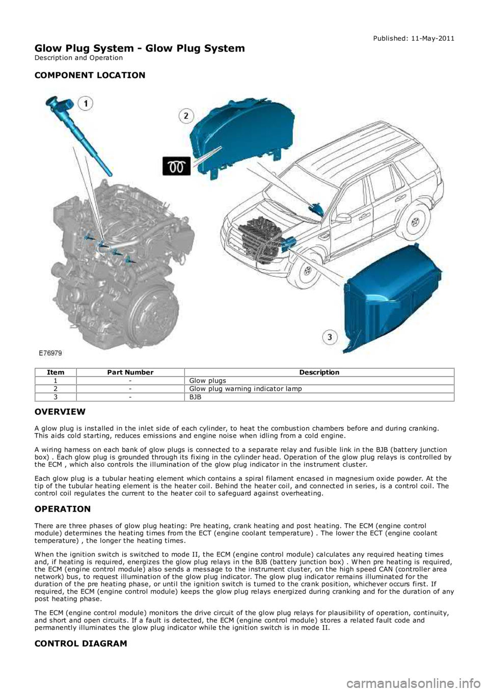
COMPONENT LOCATION
ItemPart NumberDescription
1-Glow plugs2-Glow plug warning i ndi cat or lamp
3-BJB
OVERVIEW
A gl ow plug i s i ns t alled in t he inl et si de of each cyli nder, to heat t he combus t ion chambers before and duri ng cranki ng.This ai ds col d s tarti ng, reduces emis s ions and engine nois e when idli ng from a col d engine.
A wi ri ng harnes s on each bank of glow plugs is connect ed t o a s eparat e rel ay and fusible li nk in t he BJB (bat t ery junct ionbox) . Each glow plug i s grounded through i ts fi xi ng in the cyli nder head. Operati on of the gl ow plug relays is cont roll ed byt he ECM , which al so cont rols the i ll uminati on of the gl ow plug indicator in the instrument cl us t er.
Each gl ow pl ug is a tubular heati ng element which cont ains a spi ral fi lament encas ed i n magnesi um oxide powder. At t het ip of t he tubular heati ng element is the heater coil . Behi nd the heat er coil , and connect ed i n s eries , is a cont rol coil . Thecont rol coil regulat es the current to the heat er coil t o s afeguard agains t overheat ing.
OPERATION
There are t hree phases of glow plug heati ng: Pre heati ng, crank heat ing and pos t heat ing. The ECM (engi ne cont rolmodule) determines t he heat ing ti mes from the ECT (engi ne cool ant temperat ure) . The lower t he ECT (engi ne coolantt emperature) , t he l onger t he heat ing t imes .
W hen t he i gni ti on s wit ch is s wi tched to mode II, t he ECM (engi ne cont rol module) calculates any requi red heat ing t imesand, i f heat ing is requi red, energizes the gl ow pl ug relays i n t he BJB (bat tery juncti on box) . W hen pre heati ng is required,t he ECM (engi ne cont rol module) als o s ends a mes s age to the i nst rument clus t er, on the high s peed CAN (cont roll er areanetwork) bus , to request i ll uminati on of the gl ow pl ug indicator. The gl ow pl ug indicator remains il lumi nat ed for thedurat ion of t he pre heati ng phase, or unti l the i gni ti on s wit ch is t urned t o t he crank pos it ion, whichever occurs fi rs t. Ifrequired, the ECM (engine control modul e) keeps t he glow pl ug rel ays energi zed during cranking and for the durati on of anypost heat ing phase.
The ECM (engi ne cont rol module) moni tors the drive circui t of the gl ow plug relays for pl aus i bi li ty of operat ion, cont inuit y,and s hort and open ci rcuit s . If a fault i s detected, the ECM (engine cont rol module) s tores a rel ated faul t code andpermanentl y il lumi nat es t he glow pl ug indicator whi le t he i gni ti on s wit ch is i n mode II.
CONTROL DIAGRAM
Page 1133 of 3229
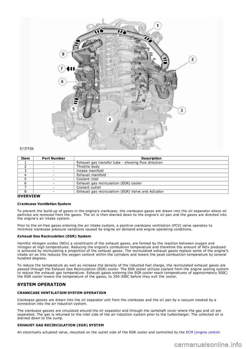
ItemPart NumberDescription
1-Exhaus t gas t rans fer t ube - showi ng fl ow direct ion2-Throt t le body
3-Intake mani fold
4-Exhaus t mani fold5-Coolant i nl et
6-Exhaus t gas reci rculati on (EGR) cooler
7-Coolant outl et8-Exhaus t gas reci rculati on (EGR) Val ve and Act uator
OVERVIEW
Crankcase Ventilation System
To prevent the bui ld-up of gas es in the engine's crankcase, t he crankcas e gas es are drawn int o t he oil s eparator where oi lpart icles are removed from the gas es . The oi l is t hen drai ned down to the engine's oi l pan and the gas es are di rected intot he engi ne's air i nt ake s ys t em.
Pri or to t he oil -free gas es entering t he air i ntake s yst em, a pos it ive crankcas e venti lat ion (PCV) val ve operat es t omi ni mi ze crankcase pres sure vari at ions caused by engi ne air demand and engi ne operati ng condi ti ons .
Exhaust Gas R ecirculation (EGR) System
Harmful nit rogen oxides (NO x) a cons ti tuent of the exhaust gas es, are formed by t he react ion between oxygen andnit rogen at high t emperat ures . Reducing t he engine's combust ion temperat ure and t herefore t he amount of NO x producedis achieved by reci rculati ng a proporti on of the exhaust gas es. The reci rculat ed exhaus t gas es repl ace some of the engine'sint ake air as t hi s reduces the oxygen cont ent wit hin t he cyl inders and lowers t he peak combus t ion t emperat ure by s everalhundred degrees.
To reduce t he temperature as well as i ncreas e t he densi ty of t he i nducted fuel charge, t he recircul ated exhaus t gas es arepass ed t hrough t he Exhaus t Gas Reci rculati on (EGR) cooler. The EGR cool er ut il izes cool ant from t he engi ne cool ing s yst emt o reduce the exhaust gas t emperat ure. Exhaus t gas es ent ering t he EGR cooler reach temperatures of approxi matel y 500C;t he EGR cool er lowers t he t emperature of t he gas es , to 250-300C before t hey exit t he cool er.
SYSTEM OPERATION
CRANKCASE VENT ILAT ION SYST EM OPERAT IO N
Crankcas e gas s es are drawn int o t he oil s eparator unit from the crankcase and the oil pan by a vacuum creat ed by aconnecti on int o t he air inducti on sys t em.
The crankcas e gas ses are circul at ed around t he oil s eparator and t hrough t he cams haft cover where t he gas and oil ares eparated. The gas is returned to the i nlet s ide of t he air inducti on s ys t em prior to the t urbocharger. The collected oi l isdrai ned down to the s ump.
EXHAUST GAS RECIR CULAT ION (EGR) SYST EM
An elect ricall y actuated val ve, mounted on the out let s ide of t he EGR cooler and cont rol led by t he ECM (engi ne cont rol