2006 LAND ROVER FRELANDER 2 engine coolant
[x] Cancel search: engine coolantPage 1556 of 3229
Publi shed: 13-Jul-2011
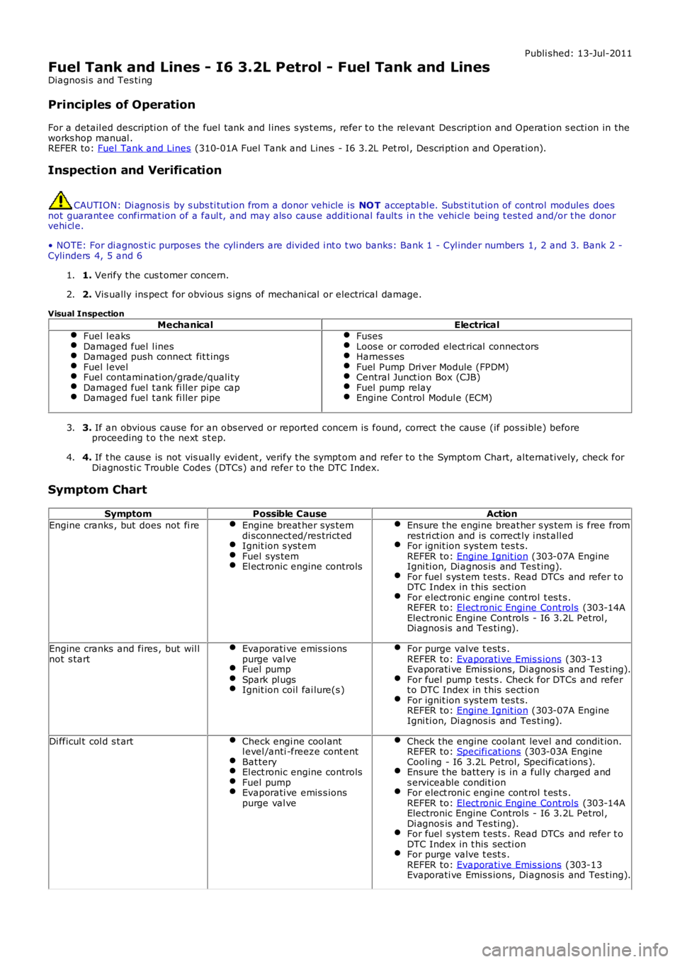
Fuel Tank and Lines - I6 3.2L Petrol - Fuel Tank and Lines
Diagnosi s and Tes ti ng
Principles of Operation
For a detail ed descripti on of the fuel tank and l ines s ys t ems , refer t o t he rel evant Des cript ion and Operat ion s ecti on in theworks hop manual .REFER to: Fuel Tank and Lines (310-01A Fuel Tank and Lines - I6 3.2L Pet rol , Descri pti on and Operat ion).
Inspection and Verification
CAUTION: Di agnos is by s ubs ti tut ion from a donor vehicle is NO T acceptabl e. Subs ti tut ion of cont rol modules doesnot guarant ee confirmat ion of a faul t, and may als o caus e addit ional fault s i n t he vehi cl e being t est ed and/or t he donorvehi cl e.
• NOTE: For di agnos t ic purpos es the cyli nders are divided i nt o t wo banks: Bank 1 - Cyl inder numbers 1, 2 and 3. Bank 2 -Cylinders 4, 5 and 6
1. Verify t he cus t omer concern.1.
2. Vis ually ins pect for obvious s igns of mechani cal or electrical damage.2.
Visual Inspection
MechanicalElectricalFuel l eaksDamaged fuel l inesDamaged push connect fit t ingsFuel l evelFuel contami nati on/grade/quali tyDamaged fuel t ank fi ller pipe capDamaged fuel t ank fi ller pipe
FusesLoos e or corroded elect rical connect orsHarnes s esFuel Pump Dri ver Module (FPDM)Central Junct ion Box (CJB)Fuel pump relayEngine Control Modul e (ECM)
3. If an obvious cause for an obs erved or report ed concern is found, correct t he caus e (if pos s ible) beforeproceeding t o t he next s t ep.3.
4. If t he caus e is not vis ually evi dent , verify t he sympt om and refer t o t he Sympt om Chart, al ternat ively, check forDi agnos ti c Trouble Codes (DTCs) and refer t o t he DTC Index.4.
Symptom Chart
SymptomPossible CauseAction
Engine cranks , but does not fi reEngine breat her sys temdi sconnect ed/res trict edIgnit ion s yst emFuel sys temEl ect ronic engine controls
Ens ure t he engi ne breat her s ys tem is free fromres t ri ct ion and is correct ly i nst all edFor ignit ion s ys tem tes t s.REFER to: Engine Ignit ion (303-07A EngineIgni ti on, Di agnos is and Tes t ing).For fuel s ys t em t est s . Read DTCs and refer t oDTC Index in t his secti onFor elect roni c engi ne cont rol t es t s .REFER to: El ect ronic Engine Cont rols (303-14AElectronic Engine Controls - I6 3.2L Petrol ,Di agnos is and Tes ti ng).
Engine cranks and fires , but wil lnot s tartEvaporati ve emis s ionspurge val veFuel pumpSpark pl ugsIgnit ion coil fai lure(s )
For purge valve t est s .REFER to: Evaporati ve Emis s ions (303-13Evaporati ve Emis s ions, Di agnos is and Tes t ing).For fuel pump t es t s . Check for DTCs and refert o DTC Index in t his s ecti onFor ignit ion s ys tem tes t s.REFER to: Engine Ignit ion (303-07A EngineIgni ti on, Di agnos is and Tes t ing).
Di fficul t col d s t artCheck engi ne cool antl evel /anti -freeze cont entBat teryEl ect ronic engine controlsFuel pumpEvaporati ve emis s ionspurge val ve
Check the engine coolant level and condit ion.REFER to: Specifi cat ions (303-03A EngineCooli ng - I6 3.2L Petrol, Speci fi cat ions ).Ens ure t he batt ery i s in a ful ly charged ands erviceable condi ti onFor elect roni c engi ne cont rol t es t s .REFER to: El ect ronic Engine Cont rols (303-14AElectronic Engine Controls - I6 3.2L Petrol ,Di agnos is and Tes ti ng).For fuel s ys t em t est s . Read DTCs and refer t oDTC Index in t his secti onFor purge valve t est s .REFER to: Evaporati ve Emis s ions (303-13Evaporati ve Emis s ions, Di agnos is and Tes t ing).
Page 1637 of 3229
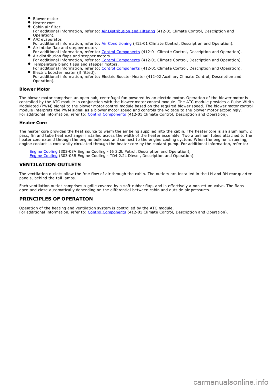
Blower mot orHeater coreCabin ai r fil ter.For addit ional informat ion, refer t o: Air Di st ri buti on and Fi lt eri ng (412-01 Climat e Cont rol, Des cript ion andOperat ion).A/C evaporat or.For addit ional informat ion, refer t o: Air Condit ioning (412-01 Cli mat e Cont rol , Descripti on and Operat ion).Air i ntake flap and s tepper motor.For addit ional informat ion, refer t o: Cont rol Component s (412-01 Cli mat e Cont rol , Descripti on and Operat ion).Air di st ri but ion fl aps and s t epper mot ors .For addit ional informat ion, refer t o: Cont rol Component s (412-01 Cli mat e Cont rol , Descripti on and Operat ion).Temperature blend flaps and s t epper mot ors .For addit ional informat ion, refer t o: Cont rol Component s (412-01 Cli mat e Cont rol , Descripti on and Operat ion).Electric boos ter heater (if fi tt ed).For addit ional informat ion, refer t o: Electric Boos ter Heater (412-02 Auxi li ary Cl imat e Control, Des cript ion andOperat ion).
Blower Motor
The blower mot or compris es an open hub, centrifugal fan powered by an elect ric motor. Operati on of the bl ower motor iscont rol led by t he ATC module in conjuncti on wit h t he blower mot or control modul e. The ATC module provi des a Puls e W i dthModulated (PW M) si gnal t o t he blower motor control modul e based on the requi red bl ower speed. The bl ower motor cont rolmodule i nterprets the PW M s ignal as a blower mot or speed and controls t he volt age to t he blower mot or accordingl y.For addit ional informat ion, refer t o: Cont rol Component s (412-01 Cli mat e Cont rol , Descripti on and Operat ion).
Heater Core
The heat er core provi des t he heat s ource to warm the ai r bei ng s uppl ied i nto t he cabin. The heat er core is an alumi num, 2pass , fin and t ube heat exchanger ins t al led acros s t he widt h of t he heat er ass embly. Two al uminum tubes att ached t o t heheat er core extend t hrough t he engi ne bulkhead and connect t o t he engine cool ing s ystem. W hen the engine is runni ng,engi ne cool ant is const antl y ci rculat ed through the heater core by the coolant pump. For addit ional informati on, refer t o:
Engi ne Cool ing (303-03A Engine Cooli ng - I6 3.2L Petrol, Des cript ion and Operat ion),Engi ne Cool ing (303-03B Engine Cooli ng - TD4 2.2L Di esel , Descri pti on and Operat ion).
VENTILATION OUTLETS
The vent il ati on out let s all ow t he free flow of ai r through t he cabi n. The out let s are ins tall ed in the LH and RH rear quart erpanel s, behind the t ail lamps .
Each vent ilat ion out let compri ses a gril le covered by a s oft rubber fl ap, and i s effect ively a non-ret urn val ve. The flapsopen and cl ose aut omat ical ly depending on t he different ial between cabin and out si de air pres s ures .
PRINCIPLES OF OPERATION
Operat ion of t he heat ing and venti lat ion s ys tem is controlled by the ATC modul e.For addit ional informat ion, refer t o: Cont rol Component s (412-01 Cli mat e Cont rol , Descripti on and Operat ion).
Page 1645 of 3229
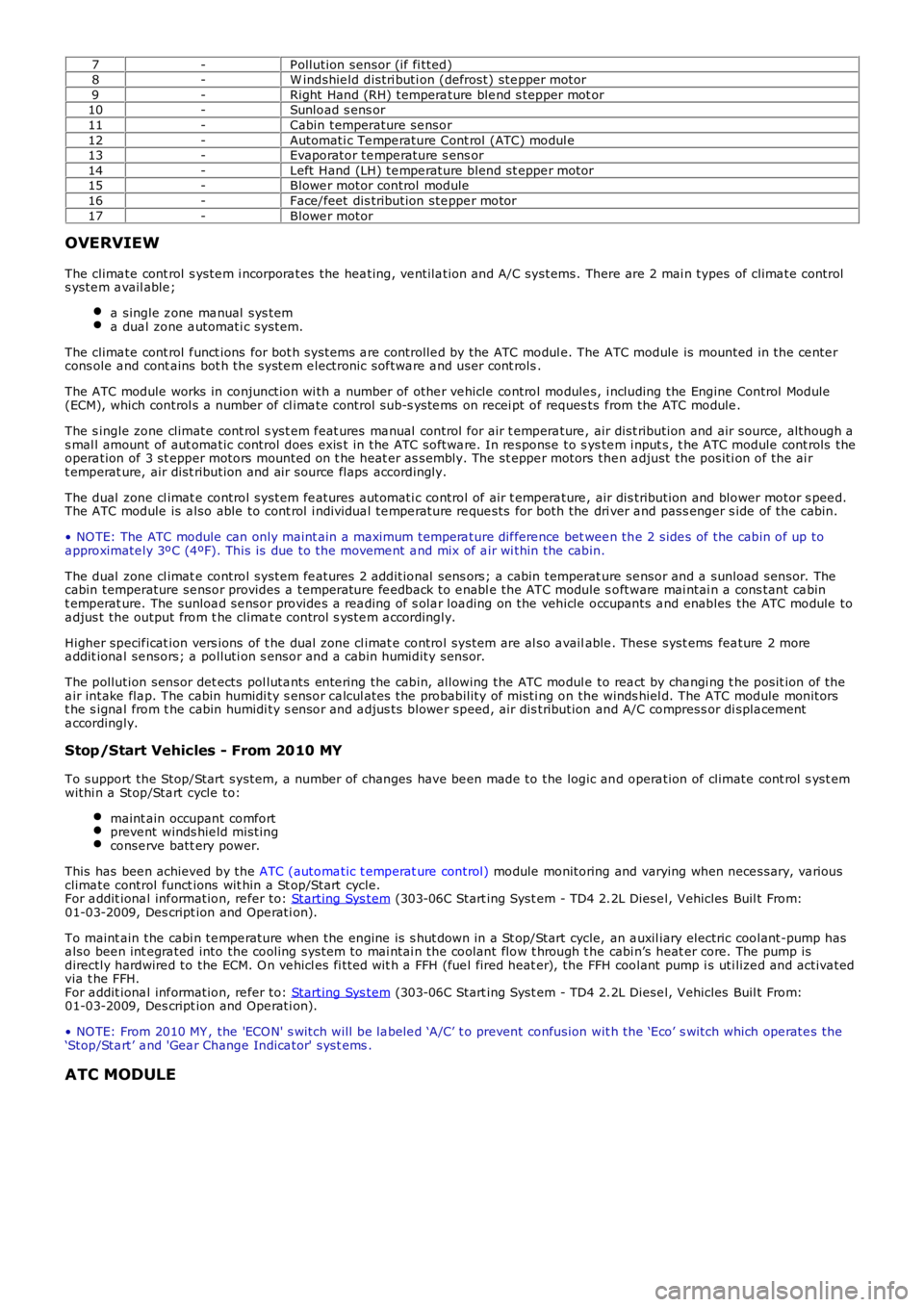
7-P ollution sensor (if fi tted)8-W indshie ld distri buti on (defrost) ste pper motor9-Right Hand (RH) tempera ture ble nd s tepper mot or10-Sunload s ens or11-Cabin temperature se nsor12-Automati c Te mpe rature Cont rol (ATC) modul e13-Evaporator te mpe rature s ens or14-Left Hand (LH) te mpe rature blend st eppe r motor15-Blowe r motor control module16-Face/feet dis tribution ste ppe r motor17-Blowe r motor
OVERVIEW
The clima te cont rol s yste m i ncorpora tes the hea ting, ve ntila tion and A/C systems. There are 2 mai n types of clima te controls yste m a vail able ;
a single z one ma nual sys tema dua l zone a utomati c system.
The clima te cont rol f unct ions for bot h systems a re controlle d by the ATC modul e. The ATC module is mounted in the ce nte rcons ole a nd cont ains bot h the syste m e lectronic sof twa re a nd user cont rols .
The ATC module works in conjunction wi th a number of othe r ve hicle control module s, i ncluding the Engine Control Module(ECM), which control s a number of cl ima te control sub-s yste ms on recei pt of reques ts f rom the ATC module .
The s ingle zone climate cont rol s yst em f eat ures ma nual control for air t empera ture , air dist ribution and air source, although as mal l amount of aut oma tic control does exis t in the ATC softwa re. In re sponse to s yste m i nput s, t he ATC module cont rols theopera tion of 3 st epper motors mounted on t he heat er as sembly. The st eppe r motors then a djust the positi on of the ai rt emperat ure, air dist ribution and air source flaps accordingly.
The dual zone cl imat e control system fe atures a utomati c control of air t empera ture , air dis tribution and blower motor s pee d.The ATC module is a lso able to cont rol i ndividua l te mpe rature re que sts for both the dri ver a nd pass enger s ide of the cabin.
• NO TE: The ATC module can only maint ain a maximum tempera ture dif fere nce bet wee n the 2 side s of the cabin of up toa pproximate ly 3ºC (4ºF). This is due to the moveme nt a nd mix of a ir wi thin the cabin.
The dual zone cl imat e control system fe atures 2 additional sens ors; a cabin temperature se nsor and a sunload sensor. Thecabin temperature se nsor provides a temperature fe edback to e nabl e the ATC module s oftware mai ntai n a cons tant ca bint emperat ure. The sunloa d se nsor provide s a rea ding of s ola r loa ding on the vehicle occupants a nd enables the ATC module toa djus t the output from t he clima te control s yste m a ccordingly.
Higher specif icat ion vers ions of t he dual zone cl imat e control system are al so a vailable . These syst ems fea ture 2 morea ddit iona l se nsors; a polluti on s ensor and a cabin humidity sensor.
The pollution sensor det ects pol luta nts ente ring the cabin, allowing the ATC modul e to rea ct by cha ngi ng t he posit ion of thea ir intake fla p. The cabin humidi ty s ensor ca lcul ates the probability of misti ng on the winds hiel d. The ATC module monitorst he s igna l from t he cabin humidi ty s ensor and a djus ts blowe r speed, air dis tribution and A/C compress or di spla cementa ccordingly.
Stop/Start Vehicles - From 2010 MY
To support the Stop/Start system, a number of changes have be en made to the logic and opera tion of climate cont rol s yst emwithi n a Stop/Sta rt cycle to:
maint ain occupant comfortpreve nt winds hie ld mistingconse rve batt ery power.
This has bee n achieved by the ATC (automa tic t emperat ure control) module monitoring and varying when nece ssary, va riousclima te control funct ions wit hin a St op/Start cycle.For a ddit iona l inf ormation, re fer to: Starting Sys tem (303-06C Start ing Syst em - TD4 2.2L Diese l, Vehicles Buil t From:01-03-2009, Des cript ion and Ope rati on).
To maint ain the cabi n te mpe rature when the engine is s hut down in a St op/Start cycle, an a uxil iary electric coolant-pump hasa lso bee n int egra ted into the cooling system to mai ntai n the coolant flow t hrough t he cabi n’s heat er core. The pump isdirectly hardwire d to the ECM. O n ve hicl es fi tted wit h a FFH (fue l fired heat er), the FFH coolant pump i s uti lize d and activa tedvia t he FFH.For a ddit iona l inf ormation, re fer to: Starting Sys tem (303-06C Start ing Syst em - TD4 2.2L Diese l, Vehicles Buil t From:01-03-2009, Des cript ion and Ope rati on).
• NO TE: From 2010 MY , the 'ECO N' s witch will be la bele d ‘A/C’ t o prevent confusion wit h the ‘Eco’ s witch which ope rate s the‘Stop/Sta rt’ a nd 'Gea r Change Indica tor' syst ems .
ATC MODULE
Page 1655 of 3229
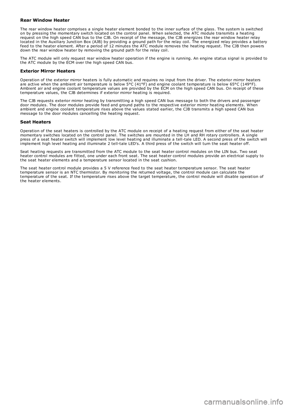
Rear Window Heater
The rear window hea ter comprise s a single heat er e leme nt bonded to the inner surf ace of t he glass . The syste m is swi tche don by pre ssing the mome nta ry s witch locate d on the control panel. W he n se lected, the ATC module tra nsmits a he atingreque st on the high spee d CAN bus to the CJB. On recei pt of the me ssa ge, the CJB energiz es t he rear window hea ter relayl ocat ed i n the Auxilia ry Junct ion Box (AJB) by providing a ground pa th for the re lay coil. The energiz ed relay provide s a bat teryf eed to t he heat er e leme nt. Afte r a period of 12 minute s the ATC module re moves the heat ing request . The CJB then powe rsdown the rea r wi ndow he ate r by removing the ground pa th f or t he relay coil .
The ATC module will only reques t re ar window heate r opera tion if the e ngine is running. An engine stat us s ignal is provide d tot he ATC module by t he ECM over the high speed CAN bus.
Exterior Mirror Heaters
O peration of the ext erior mirror heat ers is fully a utomat ic a nd re qui res no input from the driver. The exterior mirror hea tersa re a ctive when the ambient air tempera ture is below 5°C (41°F) and e ngine coolant te mpe rature i s be low 65° C (149° F).Ambi ent air a nd engine coola nt t empera ture val ues are provided by the ECM on the high speed CAN bus. O n re ceipt of the set emperat ure values, the CJB det ermines if e xterior mirror he ating is require d.
The CJB requests exterior mirror hea ting by transmit ting a high spe ed CAN bus mes sage to bot h the drivers and pa sse ngerdoor module s. The door modules provide fee d and ground paths to the respecti ve e xterior mirror he ating el eme nts . W hena mbi ent and engine cool ant tempera ture ris es a bove the va lues sta ted earl ier, the CJB transmi ts a high speed CAN busmess age to the door module s ca nce lling the hea ting reques t.
Seat Heaters
O peration of the sea t he aters is controll ed by the ATC module on re ceipt of a heati ng reque st f rom either of the se at heat ermomenta ry s witches loca ted on the cont rol pane l. The s witches are mounte d in the LH and RH rota ry controllers. A singlepress of a se at heat er switch wi ll implement low level heati ng a nd illumina te a tell-tale LED. A second pre ss of the switch willi mple me nt high l eve l hea ting and ill uminate 2 te ll-t ale LED's. A third press of t he s witch will turn t he s eat hea ter off.
Seat hea ting request s are transmitte d from the ATC module to the seat hea ter control modules on the LIN bus . Two se atheat er control modul es a re f itted, one under each front seat . The se at heat er control modules provide an e lect rical supply tot he s eat hea ter e lement s and a tempera ture sensor loca ted in t he s eat cus hion.
The s eat hea ter cont rol module provides a 5 V reference fee d to the sea t he ate r te mpe rature s ensor. The s eat hea tert emperat ure sensor is an NTC thermistor. By monitoring the ret urne d voltage, t he control module can calculate thet emperat ure of t he s eat. If t he t empera ture rise s above the target tempera ture , the control module wi ll dis abl e operat ion oft he heat er e leme nts .
Page 1742 of 3229
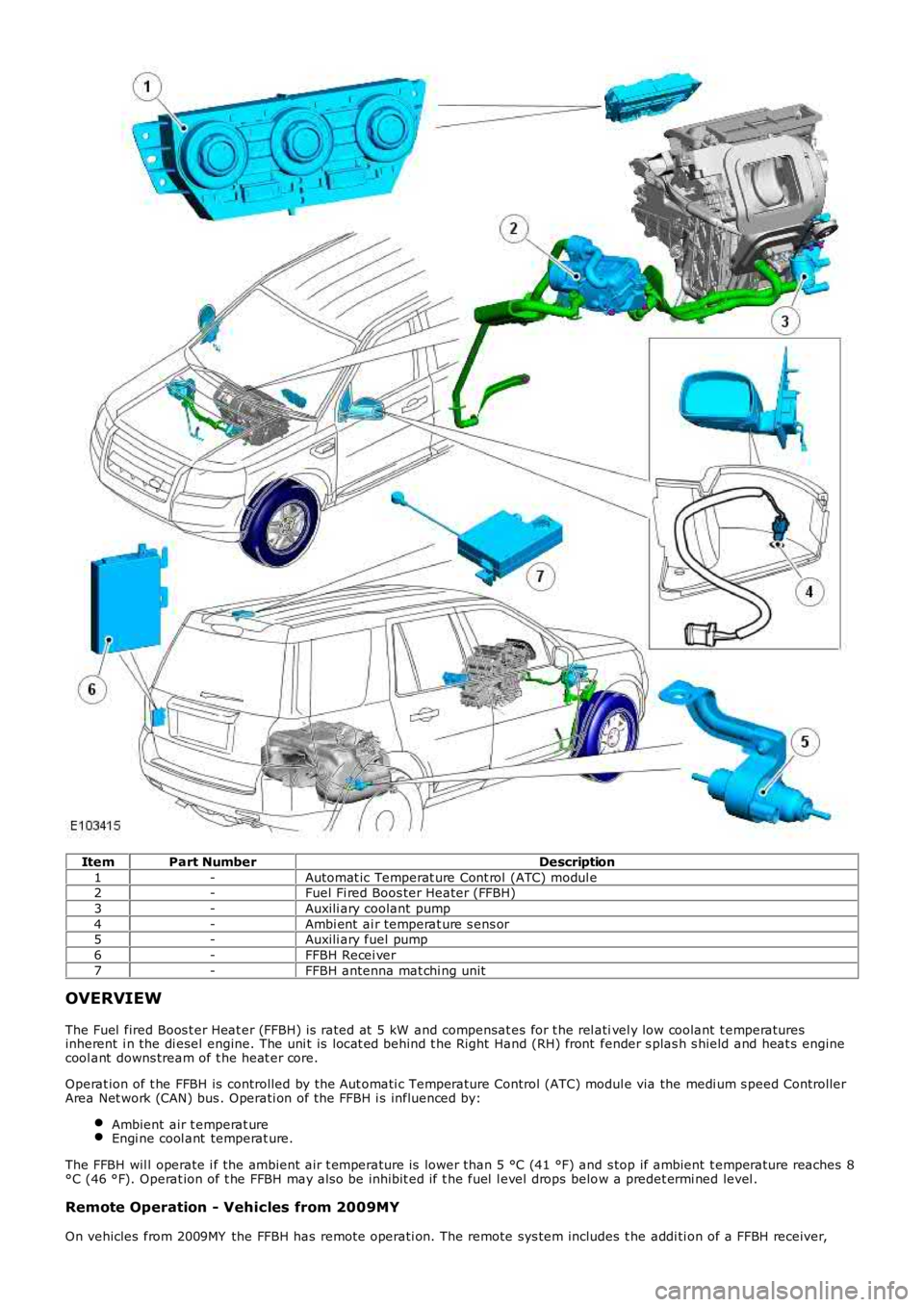
ItemPart NumberDescription
1-Automat ic Temperat ure Cont rol (ATC) modul e2-Fuel Fi red Boos ter Heater (FFBH)
3-Auxili ary coolant pump
4-Ambi ent ai r temperat ure s ens or5-Auxili ary fuel pump
6-FFBH Recei ver
7-FFBH antenna mat chi ng unit
OVERVIEW
The Fuel fired Boos t er Heat er (FFBH) is rated at 5 kW and compensat es for t he rel ativel y low coolant t emperaturesinherent i n the di esel engine. The uni t is locat ed behind t he Right Hand (RH) front fender s plas h s hield and heat s enginecool ant downs tream of t he heat er core.
Operat ion of t he FFBH is controlled by the Aut omati c Temperature Control (ATC) module via the medi um s peed ControllerArea Net work (CAN) bus . Operati on of the FFBH i s influenced by:
Ambient air t emperat ureEngi ne cool ant temperat ure.
The FFBH wil l operate i f the ambient air t emperature is lower than 5 °C (41 °F) and s top if ambient t emperature reaches 8°C (46 °F). Operat ion of t he FFBH may als o be inhibit ed if t he fuel l evel drops below a predet ermi ned level .
Remote Operation - Vehicles from 2009MY
On vehicles from 2009MY the FFBH has remote operati on. The remote sys tem includes t he addi ti on of a FFBH receiver,
Page 1745 of 3229
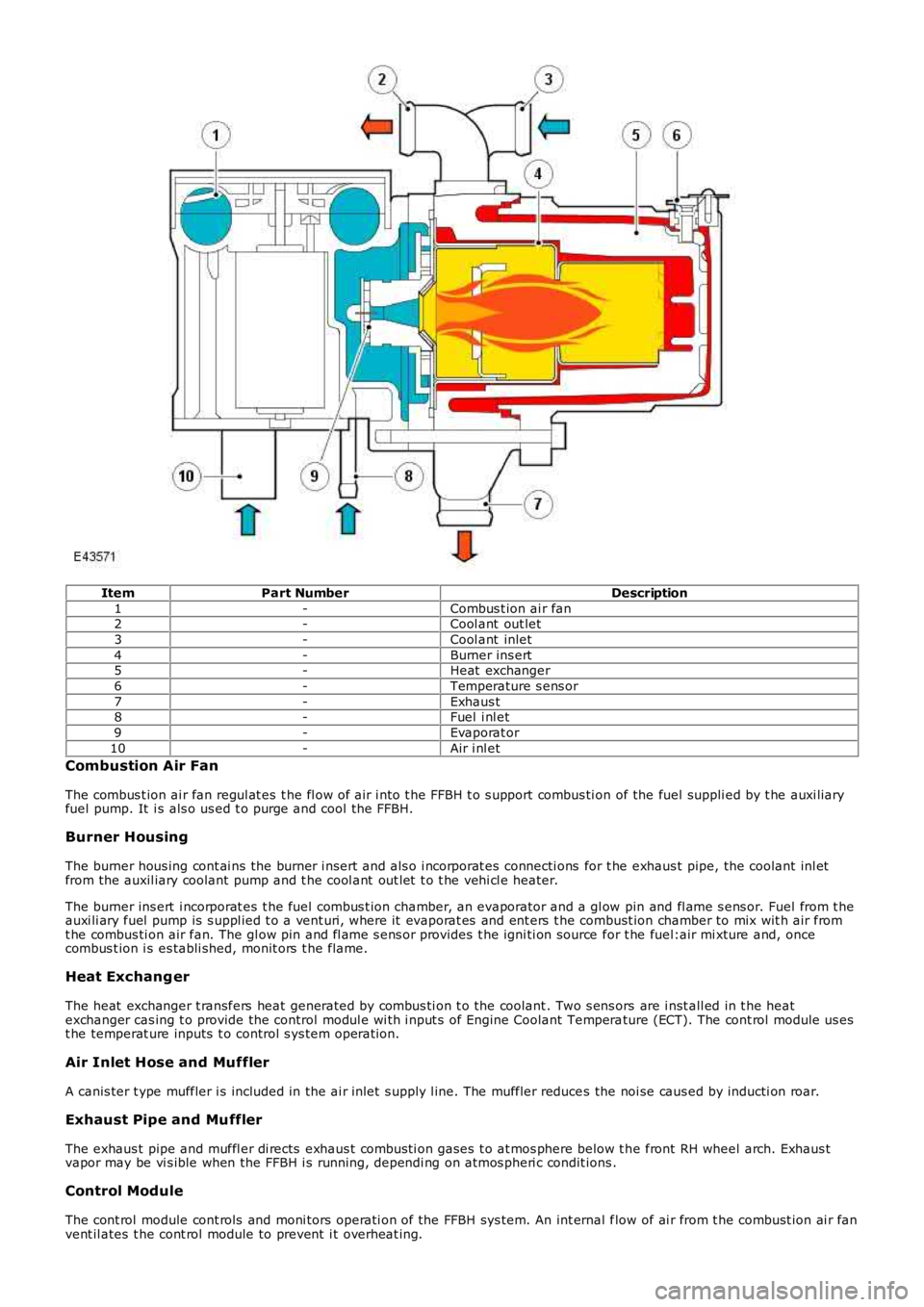
ItemPart NumberDescription
1-Combus t ion ai r fan2-Cool ant out let
3-Cool ant inlet
4-Burner ins ert5-Heat exchanger
6-Temperature s ens or
7-Exhaus t8-Fuel i nl et
9-Evaporat or
10-Air i nl et
Combustion Air Fan
The combus t ion ai r fan regul at es t he fl ow of air i nto t he FFBH t o s upport combus ti on of the fuel suppli ed by t he auxi liaryfuel pump. It i s als o us ed t o purge and cool the FFBH.
Burner Housing
The burner hous ing cont ai ns the burner i nsert and als o i ncorporat es connecti ons for t he exhaus t pipe, the coolant inl etfrom the auxil iary coolant pump and t he cool ant out let t o t he vehi cl e heater.
The burner ins ert i ncorporat es t he fuel combus t ion chamber, an evaporator and a gl ow pin and fl ame s ens or. Fuel from t heauxi li ary fuel pump is s uppl ied t o a vent uri, where it evaporat es and ent ers t he combust ion chamber to mix wit h air fromt he combus ti on air fan. The gl ow pin and fl ame s ens or provides t he igni ti on source for t he fuel:air mi xture and, oncecombus t ion i s es tabli shed, monit ors t he flame.
Heat Exchang er
The heat exchanger t ransfers heat generated by combus ti on t o the coolant . Two s ens ors are i nst all ed in t he heatexchanger cas ing t o provide the control modul e wi th i nput s of Engine Coolant Temperature (ECT). The cont rol module us est he temperat ure inputs t o control s ys tem operati on.
Air Inlet Hose and Muffler
A canis ter t ype muffler i s included in the ai r inlet s upply l ine. The muffler reduces the noi se caus ed by inducti on roar.
Exhaust Pipe and Muffler
The exhaus t pipe and muffl er di rects exhaus t combus ti on gases t o at mos phere below t he front RH wheel arch. Exhaus tvapor may be vi s ible when the FFBH i s running, dependi ng on atmos pheri c condit ions .
Control Module
The cont rol module cont rols and moni tors operati on of the FFBH sys tem. An int ernal flow of ai r from t he combust ion ai r fanvent il ates t he cont rol module to prevent i t overheat ing.
Page 1746 of 3229
The cont rol module is powered by a permanent feed from the Bat t ery Junct ion Box (BJB), and communi cat es wi th t he ATCmodule over the medium speed Controller Area Network (CAN) bus .
AUXILIARY COOLANT PUMP
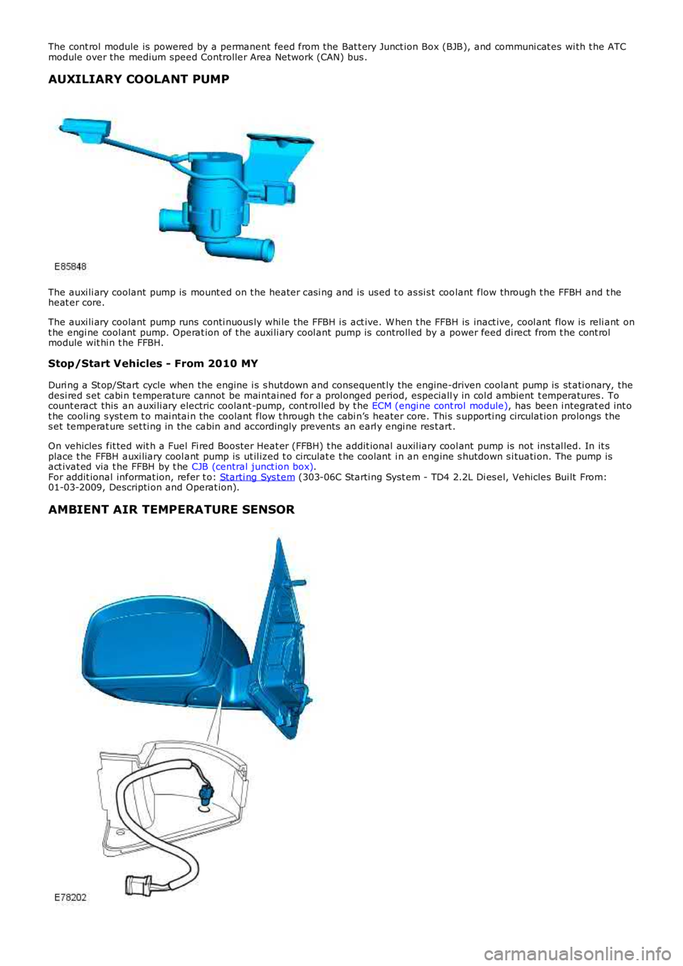
The auxi li ary coolant pump is mount ed on t he heater cas i ng and is us ed t o as si s t coolant flow through t he FFBH and t heheat er core.
The auxi li ary coolant pump runs conti nuous ly whi le the FFBH i s act ive. W hen t he FFBH is inact ive, cool ant flow is reli ant ont he engi ne cool ant pump. Operat ion of t he auxi li ary cool ant pump is controll ed by a power feed di rect from t he cont rolmodule wit hi n t he FFBH.
Stop/Start Vehicles - From 2010 MY
Duri ng a St op/Start cycle when the engine i s s hutdown and consequent ly the engine-driven coolant pump is st ati onary, thedesi red s et cabi n t emperature cannot be mai ntai ned for a prol onged period, especially in col d ambient t emperatures . Tocount eract this an auxi li ary electric coolant -pump, cont rol led by t he ECM (engi ne cont rol module), has been i ntegrat ed int ot he cooli ng s yst em t o mai ntai n the coolant flow t hrough t he cabi n’s heater core. This s upporti ng circulat ion prolongs thes et temperat ure set ti ng in the cabin and accordingly prevent s an earl y engi ne res t art .
On vehicles fit ted wit h a Fuel Fi red Boos ter Heat er (FFBH) t he addit ional auxil iary cool ant pump is not ins t al led. In it splace t he FFBH auxi liary cool ant pump is ut il ized t o circulat e t he cool ant i n an engine s hutdown s i tuati on. The pump isact ivat ed via t he FFBH by t he CJB (central junct ion box).For addit ional informat ion, refer t o: Starti ng Sys t em (303-06C Starti ng Syst em - TD4 2.2L Di es el, Vehicles Bui lt From:01-03-2009, Descripti on and Operat ion).
AMBIENT AIR TEMPERATURE SENSOR
Page 1751 of 3229
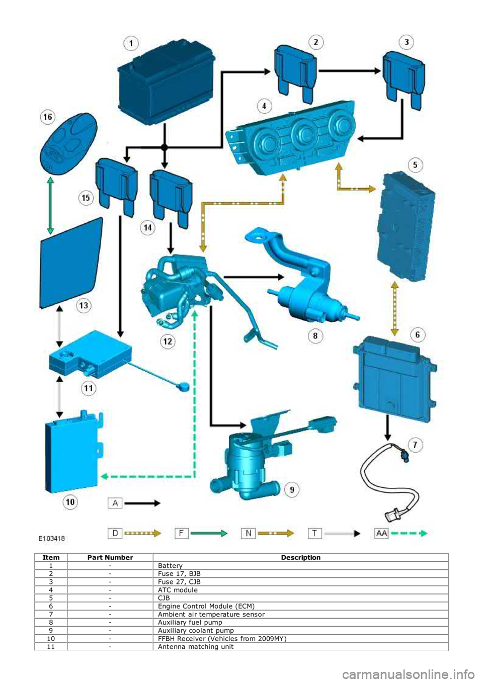
ItemPart NumberDescription
1-Bat tery2-Fus e 17, BJB
3-Fus e 27, CJB
4-ATC modul e5-CJB
6-Engine Cont rol Modul e (ECM)
7-Ambi ent ai r temperat ure sens or8-Auxil iary fuel pump
9-Auxil iary coolant pump
10-FFBH Receiver (Vehicles from 2009MY )11-Ant enna matching unit