2006 LAND ROVER FRELANDER 2 engine coolant
[x] Cancel search: engine coolantPage 2564 of 3229
Publ is hed: 11-May-2011
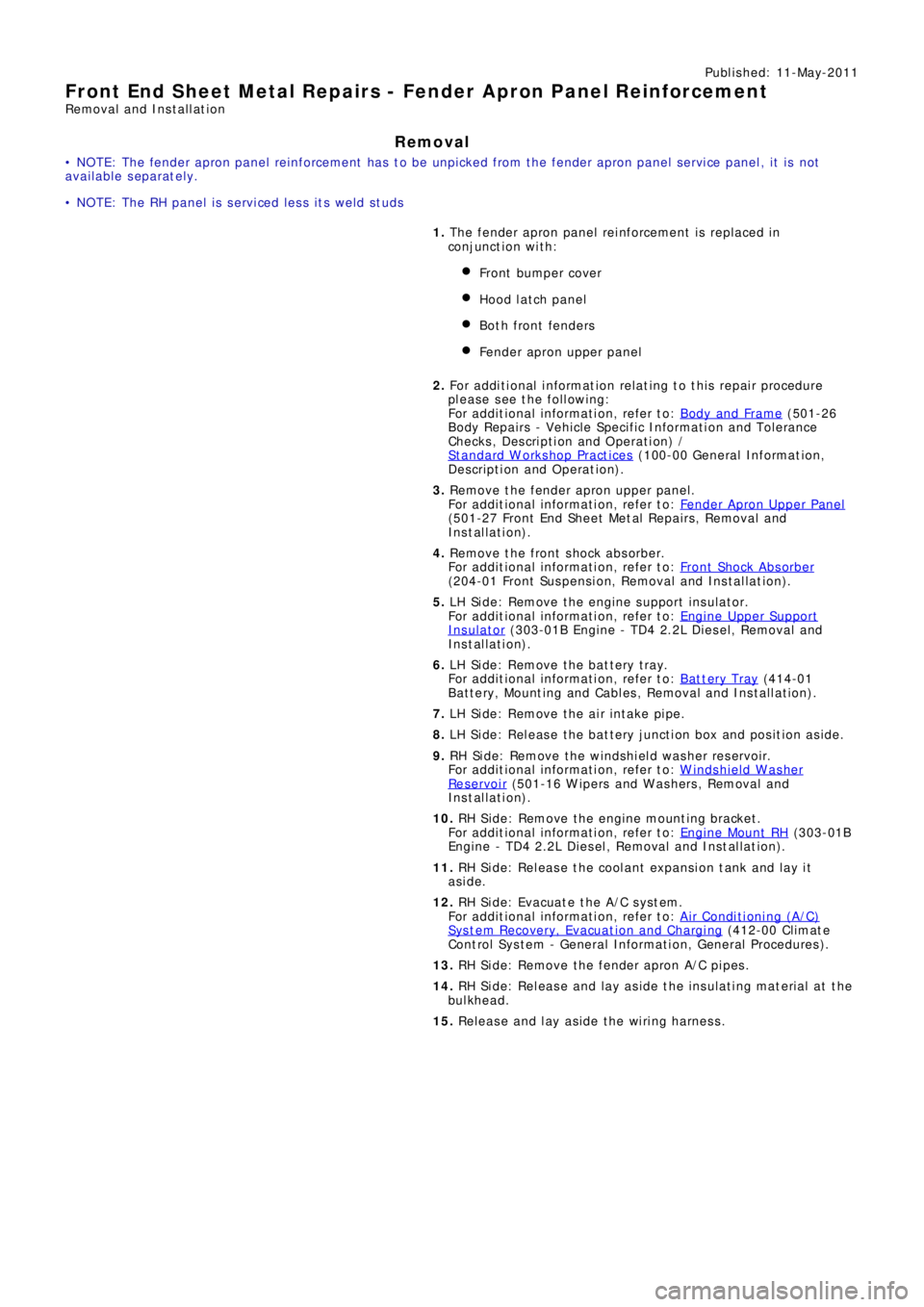
Front End Sheet Metal Repairs - Fender Apron Panel Reinforcement
Removal and Installation
Removal
• NOTE: The fender apron panel reinforcement has to be unpicked from the fender apron panel service panel, it is not
available separately.
• NOTE: The RH panel is serviced less its weld studs 1. T he f e nd e r a p ro n p a ne l re i nf o rce me nt i s re p l a ce d i n
conjunct ion wit h:
Front bumper cover
Hood lat ch panel
Both front fenders
Fender apron upper panel
2. Fo r a d d i t i o na l i nf o rma t i o n re l a t i ng t o t hi s re p a i r p ro ce d ure
please see the following:
Fo r a d d i t i o na l i nf o rma t i o n, re f e r t o : Body and Frame
(501-26
Body Repairs - Vehicle Specific Information and Tolerance
Checks, Description and Operation) /
St a nd a rd W o rks ho p P ra ct i ce s
(100-00 Ge ne ra l I nf o rma t i o n,
Description and Operation).
3. Remove the fender apron upper panel.
Fo r a d d i t i o na l i nf o rma t i o n, re f e r t o : Fender Apron Upper Panel
(501-27 Front End Sheet Met al Re pai rs , Removal and
Installation).
4. Remove the front shock absorber.
Fo r a d d i t i o na l i nf o rma t i o n, re f e r t o : Front Shock Abs orber
(204-01 Front Suspension, Removal and Installation).
5. LH Side: Remove the engine support insulator.
Fo r a d d i t i o na l i nf o rma t i o n, re f e r t o : Engine Upper Support
Insulator (303-01B Engi ne - TD4 2.2L Di es el, Removal and
Installation).
6. LH Side: Remove the bat tery t ray.
Fo r a d d i t i o na l i nf o rma t i o n, re f e r t o : Battery Tray
(414-01
Battery, Mounting and Cables, Removal and Installation).
7. LH Side: Remove the air intake pipe.
8. LH Side: Release the battery junction box and position aside.
9. RH Side: Remove the windshield washer reservoir.
Fo r a d d i t i o na l i nf o rma t i o n, re f e r t o : Windshield Washer
Res ervoi r (501-16 W i pers and W as hers , Removal and
Installation).
10. RH Side: Remove the engine mounting bracket.
Fo r a d d i t i o na l i nf o rma t i o n, re f e r t o : Engine Mount RH
(303-01B
Engine - TD4 2.2L Diesel, Removal and Installation).
11. RH Side: Release the coolant expansion tank and lay it
aside.
12. RH Side: Evacuate the A/C system.
Fo r a d d i t i o na l i nf o rma t i o n, re f e r t o : Air Conditioning (A/C)
System Recovery, Evacuation and Charging (412-00 Cl i mat e
Co nt ro l Sys t e m - Ge ne ra l I nf o rma t i o n, Ge ne ra l P ro ce d ure s ).
13. RH Side: Remove the fender apron A/C pipes.
14. RH Side: Release and lay aside the insulating material at the
bulkhead.
15. Release and lay aside the wiring harness.
Page 2725 of 3229

Contents
5
R
ENGINE COOLANT CHECK ............................ 163
BRAKE AND CLUTCH FLUID CHECK ............. 165
POWER STEERING FLUID CHECK ................ 166
WASHER FLUID CHECK ................................ 167
TECHNICAL SPECIFICATIONS ...................... 169
Vehicle battery
BATTERY WARNING SYMBOLS ................... 171
BATTERY CARE ............................................ 171
USING BOOSTER CABLES ............................ 173
CHARGING THE VE HICLE BATTERY ............. 174
CHANGING THE VE HICLE BATTERY ............. 174
Wheels and tyres
GENERAL INFORMATION ............................. 176
TYRE CARE ................................................... 177
USING WINTER TYRES................................. 183
CHANGING A ROAD WHEEL ......................... 183
TYRE REPAIR KIT ......................................... 187
USING SNOW CHAINS.................................. 192
TYRE GLOSSARY.......................................... 193
TECHNICAL SPECIFICATIONS ...................... 194
Fuses
FUSE BOX LOCATIONS ................................. 195
CHANGING A FUSE ....................................... 195
FUSE SPECIFICATION CHART....................... 196
Emergency equipment
HAZARD WARNING FLASHERS .................... 204
WARNING TRIANGLE ................................... 204
Status after a collision
DRIVING AFTER A COLLISION...................... 205
INSPECTING SAFETY SYSTEM COMPONENTS ...
206
Vehicle recovery
TOWING POINTS .......................................... 207
LASHING POINTS ......................................... 208
TRANSPORTING THE VEHICLE..................... 208
TOWING THE VEHICLE ON FOUR WHEELS .. 208
Vehicle identification
VEHICLE IDENTIFICATION PLATE................. 210
VEHICLE IDENTIFI CATION NUMBER (VIN) ... 210
VEHICLE BUILD DATE PLATE ....................... 210
Technical specifications
ENGINE SPECIFICATIONS ............................ 211
WEIGHTS...................................................... 212
DIMENSIONS................................................ 213
Type approval
Declarations of conformity ........................... 215
Audio introduction
RADIO RECEPTION....................................... 218
Audio unit overview
AUDIO UNIT OVERVIEW............................... 219
Audio unit operation
ON OR OFF CONTROL .................................. 223
VOLUME CONTROL ...................................... 223
AUDIO CONTROL ......................................... 223
WAVEBAND BUTTON ................................... 224
AUTOSTORE CONTROL ................................ 225
STATION PRESET BUTTONS ........................ 226
TRAFFIC INFORMATION CONTROL .............. 226
Audio unit menus
RADIO DATA SYSTEM (RDS) ....................... 228
REGIONAL MODE (REG) .............................. 228
ENHANCED OTHER NETWORK (RDS-EON).. 229
ALTERNATIVE FREQUENCIES ...................... 229
NEWS BROADCASTS ................................... 230
PRIORITY PROGRAMME TYPE (PTY) .......... 231
RESETTING THE AUDIO UNIT ...................... 233
Digital audio broadcasting
GENERAL INFORMATION ............................. 234
AUDIO CONTROLS ....................................... 235
DISPLAY OPTIONS ....................................... 236
CHANNEL AUTOMATIC TUNING................... 236
CHANNEL OPTIONS ..................................... 236
PRESET BUTTONS ....................................... 238
SETTINGS..................................................... 240
Compact disc player
LOADING COMPACT DISCS ......................... 245
EJECTING COMPACT DISCS ........................ 246
EJECTING MULTIPLE CO MPACT DISCS....... 246
COMPACT DISC SELECTION ........................ 246
COMPACT DISC PLAYBACK ......................... 246
Page 2741 of 3229
21
Quick start
R
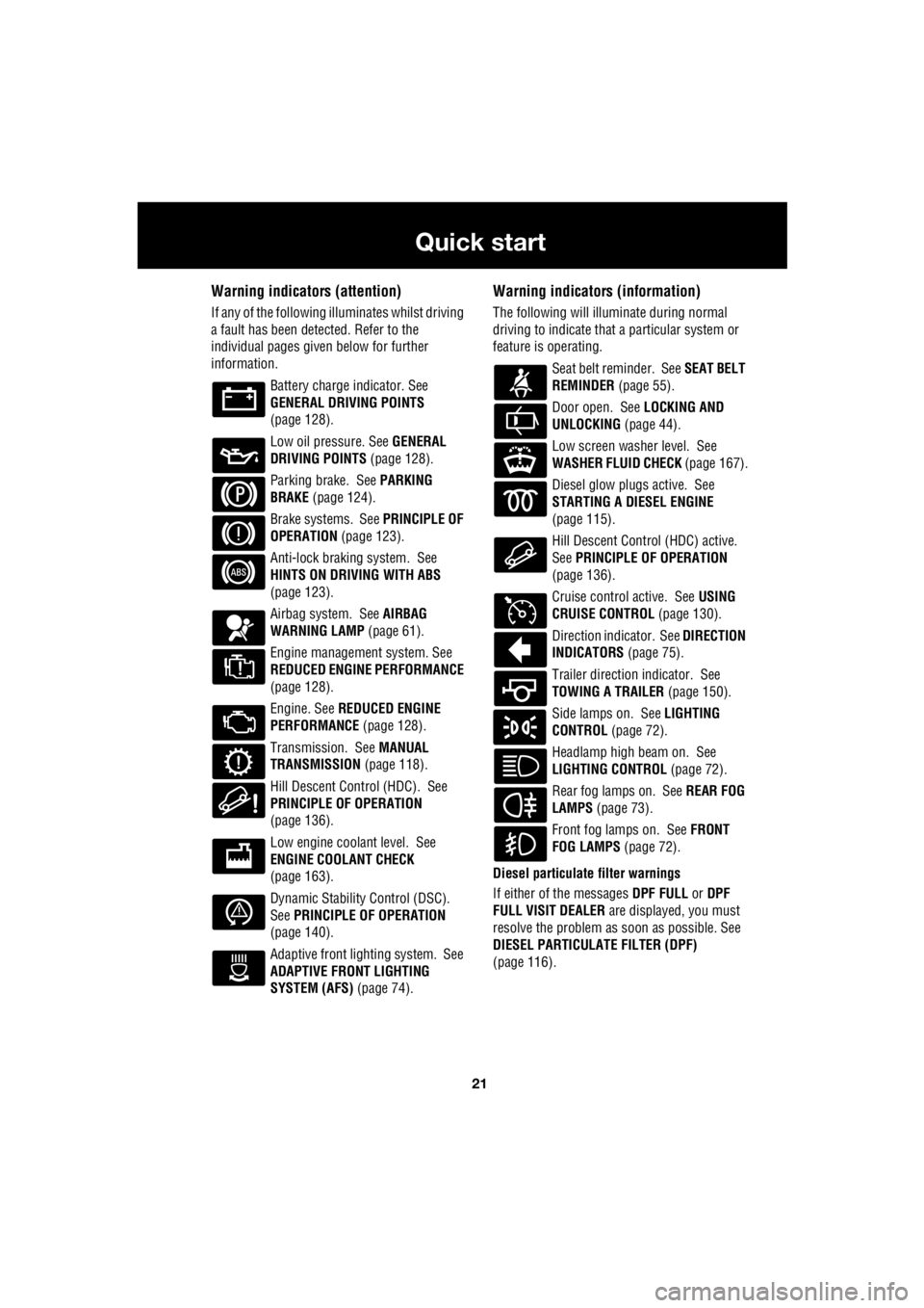
Warning indicators (attention)
If any of the following illuminates whilst driving
a fault has been detected. Refer to the
individual pages give n below for further
information.
Battery charge indicator. See
GENERAL DRIVING POINTS
(page 128).
Low oil pressure. See GENERAL
DRIVING POINTS (page 128).
Parking brake. See PARKING
BRAKE (page 124).
Brake systems. See PRINCIPLE OF
OPERATION (page 123).
Anti-lock braking system. See
HINTS ON DRIVING WITH ABS
(page 123).
Airbag system. See AIRBAG
WARNING LAMP (page 61).
Engine management system. See
REDUCED ENGINE PERFORMANCE
(page 128).
Engine. See REDUCED ENGINE
PERFORMANCE (page 128).
Transmission. See MANUAL
TRANSMISSION (page 118).
Hill Descent Control (HDC). See
PRINCIPLE OF OPERATION
(page 136).
Low engine coolant level. See
ENGINE COOLANT CHECK
(page 163).
Dynamic Stability Control (DSC).
See PRINCIPLE OF OPERATION
(page 140).
Adaptive front lighting system. See
ADAPTIVE FRONT LIGHTING
SYSTEM (AFS) (page 74).
Warning indicators (information)
The following will illuminate during normal
driving to indicate that a particular system or
feature is operating.
Seat belt reminder. See SEAT BELT
REMINDER (page 55).
Door open. See LOCKING AND
UNLOCKING (page 44).
Low screen washer level. See
WASHER FLUID CHECK (page 167).
Diesel glow plugs active. See
STARTING A DIESEL ENGINE
(page 115).
Hill Descent Control (HDC) active.
See PRINCIPLE OF OPERATION
(page 136).
Cruise control active. See USING
CRUISE CONTROL (page 130).
Direction indicator. See DIRECTION
INDICATORS (page 75).
Trailer direction indicator. See
TOWING A TRAILER (page 150).
Side lamps on. See LIGHTING
CONTROL (page 72).
Headlamp high beam on. See
LIGHTING CONTROL (page 72).
Rear fog lamps on. See REAR FOG
LAMPS (page 73).
Front fog lamps on. See FRONT
FOG LAMPS (page 72).
Diesel particulate filter warnings
If either of the messages DPF FULL or DPF
FULL VISIT DEALER are displayed, you must
resolve the problem as soon as possible. See
DIESEL PARTICULATE FILTER (DPF)
(page 116).
Page 2754 of 3229
34
Filling station information
L
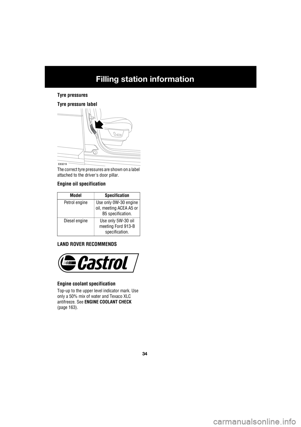
Tyre pressures
Tyre pressure label
The correct tyre pressures are shown on a label
attached to the dr iver's door pillar.
Engine oil specification
LAND ROVER RECOMMENDS
Engine coolant specification
Top-up to the upper level indicator mark. Use
only a 50% mix of water and Texaco XLC
antifreeze. See ENGINE COOLANT CHECK
(page 163). Model Specification
Petrol engine Use only 0W-30 engine oil, meeting ACEA A5 or
B5 specification.
Diesel engine Use only 5W-30 oil meeting Ford 913-B
specification.
E83219
Page 2878 of 3229
Maintenance
158
L
One or both types of serv ice interval (distance
and time) may be displayed. For example, if an
engine oil service is du e based on mileage, and
a brake fluid change is due based on time, both
distance and time c ountdowns will display.
Service Portfolio
The Service Portfolio book includes a Service
Record section, which enables a record to be
kept of all the servicing and inspections that are
carried out on the vehicle. This section of the
book also has an area for brake fluid changes
to be recorded.
Ensure your service provider signs and stamps
the book after each se rvice and inspection.
Owner Maintenance
In addition to the routine maintenance, a
number of simple checks must be carried out
more frequently. Advice is given on the pages
that follow.
Daily checks
• Operation of lamps, horn, direction
indicators, wipers, washers and warning
indicators.
• Operation of seat belts and brakes.
• Look for fluid deposits underneath the
vehicle that might indicate a leak.
Weekly checks
• Engine oil level. See ENGINE OIL CHECK
(page 162).
• Engine coolant check. See ENGINE
COOLANT CHECK (page 163).
• Brake/clutch fluid level. See BRAKE AND
CLUTCH FLUID CHECK (page 165). •
Power steering fluid level. See POWER
STEERING FLUID CHECK (page 166).
• Screen washer fluid level. See WASHER
FLUID CHECK (page 167).
• Tyre pressure s and condition.
• Operate air conditioning.
Note: The engine oil leve l should be checked
more frequently if the vehicle is driven for
prolonged periods at high speeds.
Driving in arduous conditions
When a vehicle is operated in extremely
arduous conditions, more frequent attention
must be paid to servicing requirements.
For example, if your vehicle experiences deep
wading conditions, even daily servicing could
be necessary to ensure the continued safe and
reliable operation of the vehicle.
Arduous driving conditions include:
• Driving in dusty and/or sandy conditions.
• Driving on rough and/or muddy roads
and/or wading.
• Driving in extremely hot conditions.
• Towing a trailer or driving in mountainous
conditions.
Contact a Land Rover Dealer/Authorised
Repairer for advice.
Emission control
Your vehicle is fitted with various items of
emission and evaporative control equipment,
designed to meet sp ecific territorial
requirements. You should be aware that
unauthorised replacemen t, modification or
tampering with this equipment by an owner or
repair shop, may be unlawful and subject to
legal penalties.
CAUTION
Any significant or sudden drop in fluid
levels, or uneven tyre wear, should be
reported to a qualified technician without
delay.
Page 2881 of 3229
161
Maintenance
R
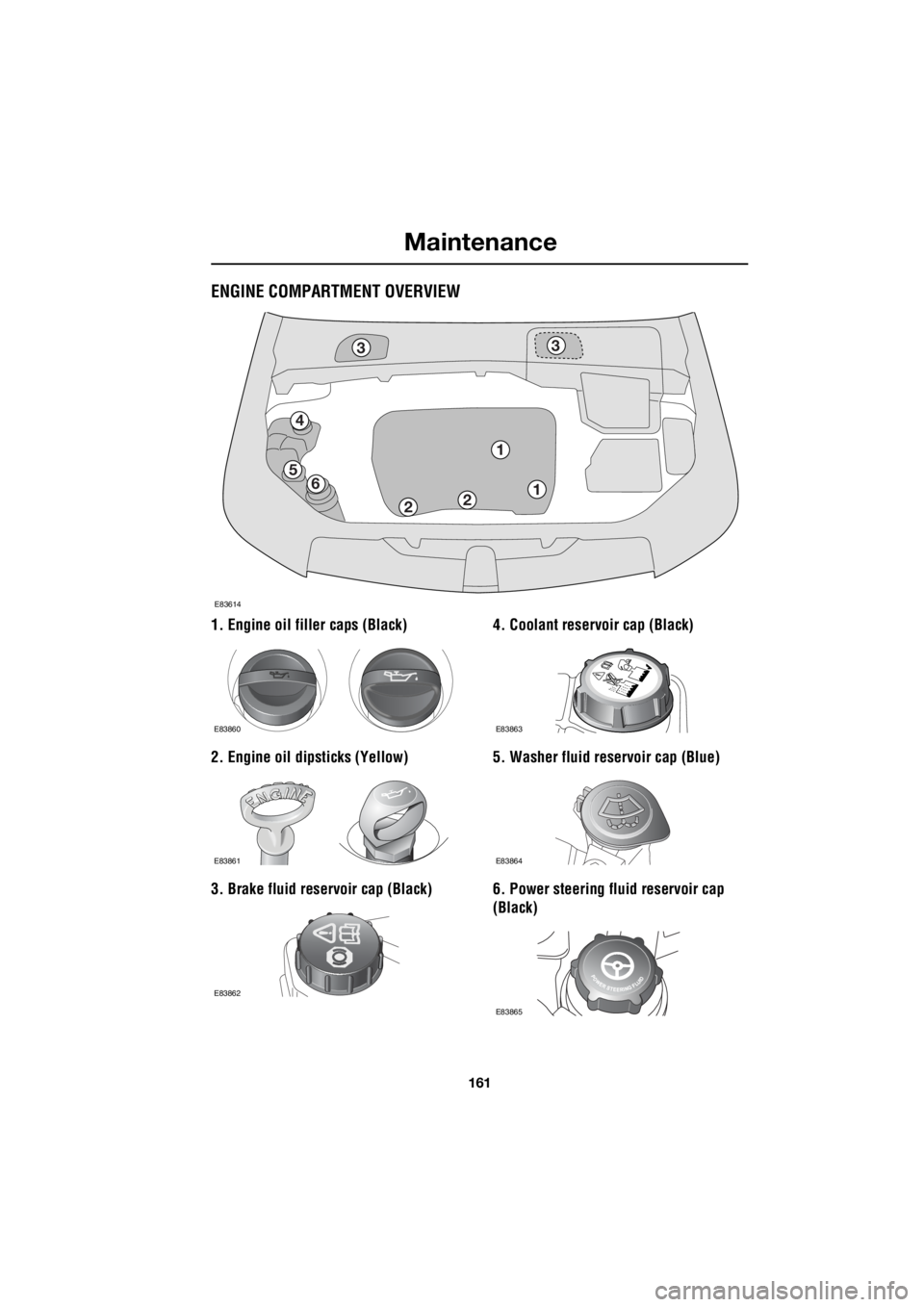
ENGINE COMPARTMENT OVERVIEW
1. Engine oil filler caps (Black)
2. Engine oil dipsticks (Yellow)
3. Brake fluid reservoir cap (Black) 4. Coolant reservoir cap (Black)
5. Washer fluid reservoir cap (Blue)
6. Power steering fluid reservoir cap
(Black)
3
4
56
21
3
1
2
E83614
E83860
E83861
E83862
E83863
E83864
E83865
Page 2883 of 3229

163
Maintenance
R
Topping up the oil
1. Unscrew the oil filler cap.
2. Add oil to maintain the level between the
MIN and MAX marks or notches on the
dipstick. Clean up any oil spilled during
topping-up.
3. Check the oil level again after 5 minutes.
It is essential to use the correct specification
oil, and to ensure it is suitable for the climatic
conditions in which the vehicle is to be
operated.
Note: The approximate quantity of oil required
to raise the level from MIN to MAX on the
dipstick is 0.8 litres (1.4 pints) - petrol models
or 1.5 litres (2.6 pi nts) - diesel models.
Engine oil specification
Land Rover recommends Castrol oils.
ENGINE COOLANT CHECK
If the quantity of fluid in the coolant
reservoir drops below the
recommended level, an amber
warning indicator in the instrument pack will
illuminate. Stop the vehicle and check the
coolant level.
On vehicles with a message centre, the
message LOW COOLANT LEVEL or COOLING
SYSTEM FAULT MONITOR GAUGE will be
displayed in place of the warning indicator.
Checking the coolant level
The coolant level in the expansion tank should
be checked at least week ly (more frequently in
high mileage or arduous operating conditions).
Always check the level when the system is
cold.
Ensure the coolant level is maintained between
the level indicator marks located on the side of
the expansion tank.
CAUTIONS
Your vehicle warranty may be invalidated
if damage is caused by using oil that
does not meet the required specification.
Failure to use an oil that meets the
required specification could cause
excessive engine wear, a build up of sludge
and deposits, and increase pollution. It could
also lead to engine failure.
Overfilling with oil could result in severe
engine damage. Oil should be added in
small quantities and the level re-checked to
ensure that the engine is not overfilled.
Model Specification
Petrol engine Use only 0W-30 engine oil, meeting ACEA A5 or
B5 specification.
Diesel engine Use only 5W-30 oil meeting Ford 913-B
specification.
CAUTION
Running the engine without coolant will
cause serious engine damage.
E83616
Page 2884 of 3229
Maintenance
164
L
If the level has fallen appreciably, suspect
leakage or overheatin g and arrange for the
vehicle to be exam ined by a qualified
technician.
Topping up the coolant
Top-up to the upper le vel indicator mark
located on the side of the expansion tank. Use
only a 50% mix of water and Texaco XLC
antifreeze.
Note: In an emergency - and only if the
approved antifreeze is unavailable - top-up the
cooling system with clea n water, but be aware
of the resultant reduction in frost protection.
Do not top-up or refill with conventional
antifreeze formulations. If in doubt consult a
qualified technician.
Ensure the cap is tightened fully after top-up is
completed by turning the cap until the ratchet
cap clicks. Antifreeze
Antifreeze contains important corrosion
inhibitors. The antifreeze content of the coolant
must be maintained at 50% ± 5% all year round
(not just in cold conditions). To ensure that the
anti-corrosion properties of the coolant are
retained, the antifreeze content should be
checked once a year and completely renewed
every ten years, regardless of distance
travelled. Failure to do so may cause corrosion
of the radiator and engine components.
The specific gravity of a 50% antifreeze
solution at 20°C (68°F) is 1.068 and protects
against frost down to -40°C (-40°F).
WARNINGS
Never remove the filler cap when the
engine is hot - escaping steam or
scalding water could ca use serious personal
injury.
Avoid spilling antifreeze onto a hot
engine - a fire may result.
Unscrew the filler cap slowly, allowing
the pressure to escape before removing
completely.
CAUTION
When travelling in territories where the
water supply contains salt, always
ensure you carry a supply of fresh (rain or
distilled) water. Topping up with salt water will
cause serious engine damage.
WARNINGS
Antifreeze is poisonous and can be fatal
if swallowed - keep containers sealed
and out of the reach of children. If accidental
consumption is suspec ted, seek medical
attention immediately.
If the fluid comes into contact with the
skin or eyes, rinse immediately with
plenty of water.
CAUTIONS
The use of non-approved antifreeze will
have an adverse ef fect on the engine
cooling system and therefore engine
durability.
Antifreeze will damage painted surfaces;
soak up any spillage with an absorbent
cloth immediately and wash the area with a
mixture of car shampoo and water.