2006 DODGE RAM SRT-10 battery
[x] Cancel search: batteryPage 4874 of 5267
B10A9–RIGHT BLEND DOOR CONTROL CIRCUIT/PERFORMANCE (DUAL-ZONE)
For a complete wiring diagramRefer to Section 8W.
Theory of Operation
The A/C Heater Control monitors the door driver circuits during actuator operation for shorts to ground, shorts to
battery, and shorts to other door driver circuits. If detected, the A/C Heater Control reports these types of faults as
Control Circuit/Performance DTCs. It is important to note that Control Circuit/Performance DTCs do not indicate
where or what type of short is present and that additional system testing isnecessary to provide more details about
the reported fault.
When Monitored:
When actuator movement is requested.
Set Condition:
If the A/C Heater Control detects an excessive current draw on any of the door driver circuits while attempting
to drive this actuator. This DTC has a maturing time of 5 seconds and a de-maturing time of 10 seconds. If the
DTC’s status changes from active to stored, it will stay in memory for 100 ignition cycles.
Possible Causes
DOOR DRIVER CIRCUIT(S) SHORTED
NOTE:TheDTCmustbeactivefortheresultsofthistesttobevalid.Donotperform this test if the DTC is
stored. Refer to HVAC System Test for stored DTC test procedures.
Diagnostic Test
1.RUN THE ACTUATOR DTC DETECTION TEST
Turn the ignition on.
With the scan tool in HVAC, erase DTCs.
With the scan tool, select System Tests and then select Actuator DTC Detection. When the test is complete, select
View DTCs.
Repair
Diagnose and repair the DTC(s). If multiple DTCs are present, beginning with the passenger blend door,
diagnose and repair all short high DTCs and then all short low DTCs. Refer tothe Table of Contents in
this Section for a complete list of HVAC related symptoms.
Page 4876 of 5267
When Monitored:
With the ignition on. Battery voltage greater than 10.4 volts.
Set Condition:
If the Totally Integrated Power Module (TIPM) detects a shorted low condition in the (C123) Condenser Fan
Control circuit.
Possible Causes
(C123) CONDENSER FAN CONTROL OUTPUT CIRCUIT SHORTED TO GROUND
CONDENSER FAN MOTOR
TIPM
Diagnostic Test
1.VERIFY DTC IS ACTIVE
Turn the ignition on.
With the scan tool, erase TIPM DTCs.
Turn the ignition off, wait 10 seconds, and turn the ignition on.
With the scan tool, actuate the Condenser Fan.
With the scan tool, read TIPM DTCs.
Does this DTC reset?
Ye s>>
With the scan tool, de-actuate the Condenser Fan. Then, Go To 2
No>>
With the scan tool, de-actuate the Condenser Fan. Then, check for an intermittent condition by inspect-
ing the related wiring harness for chafed, pierced, pinched, and partially broken wires. Also, inspect the
related connectors for broken, bent, corroded, and contaminated terminals.
Perform BODY VERIFICATION TEST – VER 1. (Refer to 8 - ELECTRICAL/ELECTRONIC CONTROL
MODULES - STANDARD PROCEDURE).
2.CHECK (C123) CONDENSER FAN CONTROL OUTPUT CIRCUIT FOR A SHORT TO GROUND
Turn the ignition off.
Disconnect the TIPM C8 harness connector.
Disconnect the Condenser Fan Motor harness connector.
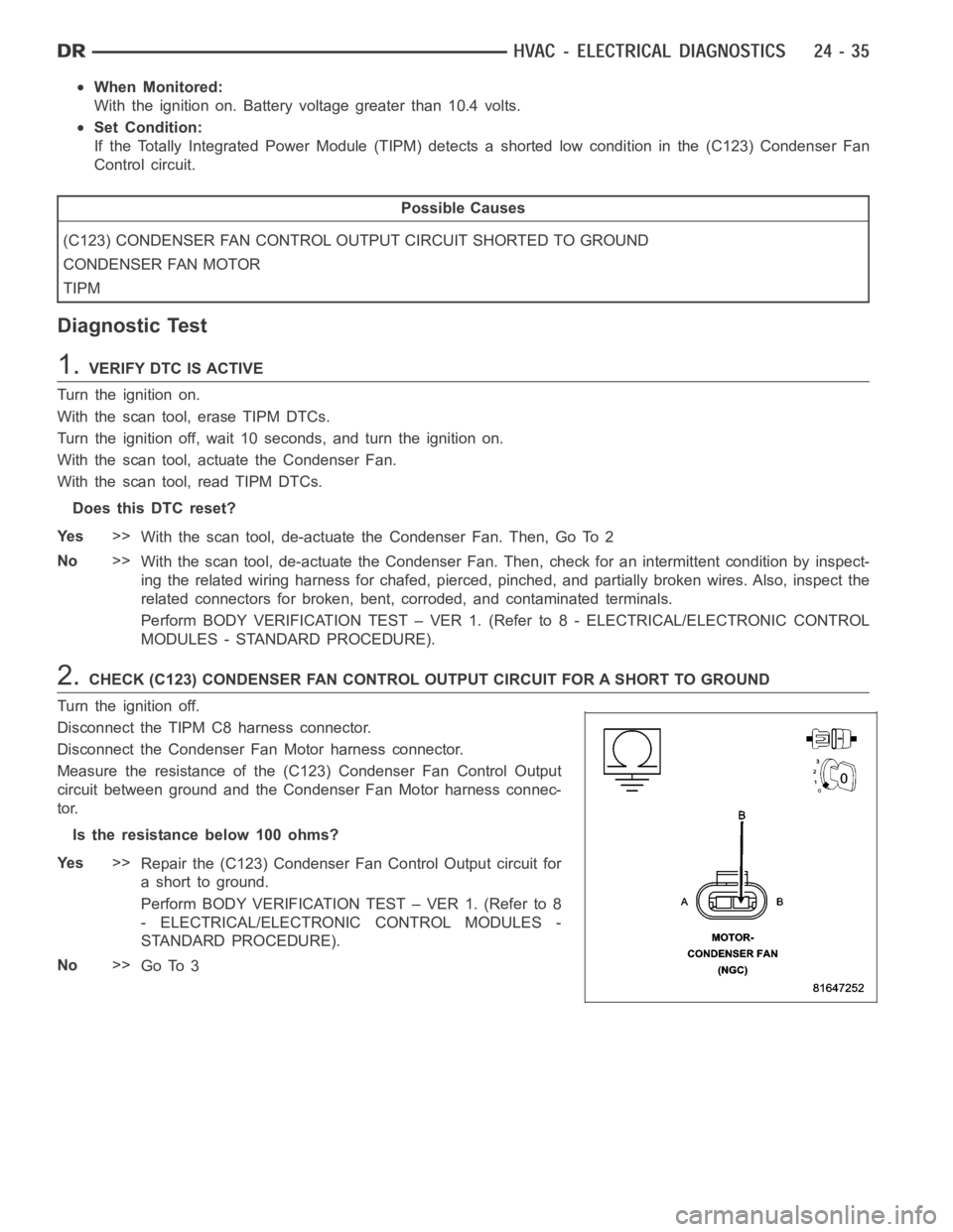
Measure the resistance of the (C123) Condenser Fan Control Output
circuit between ground and the Condenser Fan Motor harness connec-
tor.
Istheresistancebelow100ohms?
Ye s>>
Repair the (C123) Condenser Fan Control Output circuit for
a short to ground.
Perform BODY VERIFICATION TEST – VER 1. (Refer to 8
- ELECTRICAL/ELECTRONIC CONTROL MODULES -
STANDARD PROCEDURE).
No>>
Go To 3
Page 4879 of 5267
When Monitored:
With the ignition on. Battery voltage greater than 10.4 volts.
Set Condition:
If the Totally Integrated Power Module (TIPM) detects a shorted high condition in the (C123) Condenser Fan
Control circuit.
Possible Causes
(C123) CONDENSER FAN CONTROL OUTPUT CIRCUIT SHORTED TO BATTERY VOLTAGE
EXCESSIVE RESISTANCE IN THE (Z823) GROUND CIRCUIT
CONDENSER FAN MOTOR
TIPM
Diagnostic Test
1.VERIFY DTC IS ACTIVE
Turn the ignition on.
With the scan tool, erase TIPM DTCs.
Turn the ignition off, wait 10 seconds, and turn the ignition on.
With the scan tool, actuate the Condenser Fan.
With the scan tool, read TIPM DTCs.
Does this DTC reset?
Ye s>>
With the scan tool, de-actuate the Condenser Fan. Then, Go To 2
No>>
With the scan tool, de-actuate the Condenser Fan. Then, check for an intermittent condition by inspect-
ing the related wiring harness for chafed, pierced, pinched, and partially broken wires. Also, inspect the
related connectors for broken, bent, corroded, and contaminated terminals.
Perform BODY VERIFICATION TEST – VER 1. (Refer to 8 - ELECTRICAL/ELECTRONIC CONTROL
MODULES - STANDARD PROCEDURE).
2.CHECK (C123) CONDENSER FAN CONTROL OUTPUT CIRCUIT FOR A SHORT TO BATTERY VOLTA G E
Turn the ignition off
Disconnect the TIPM C8 harness connector.
Disconnect the Condenser Fan Motor harness connector.
Ignition on, engine not running.
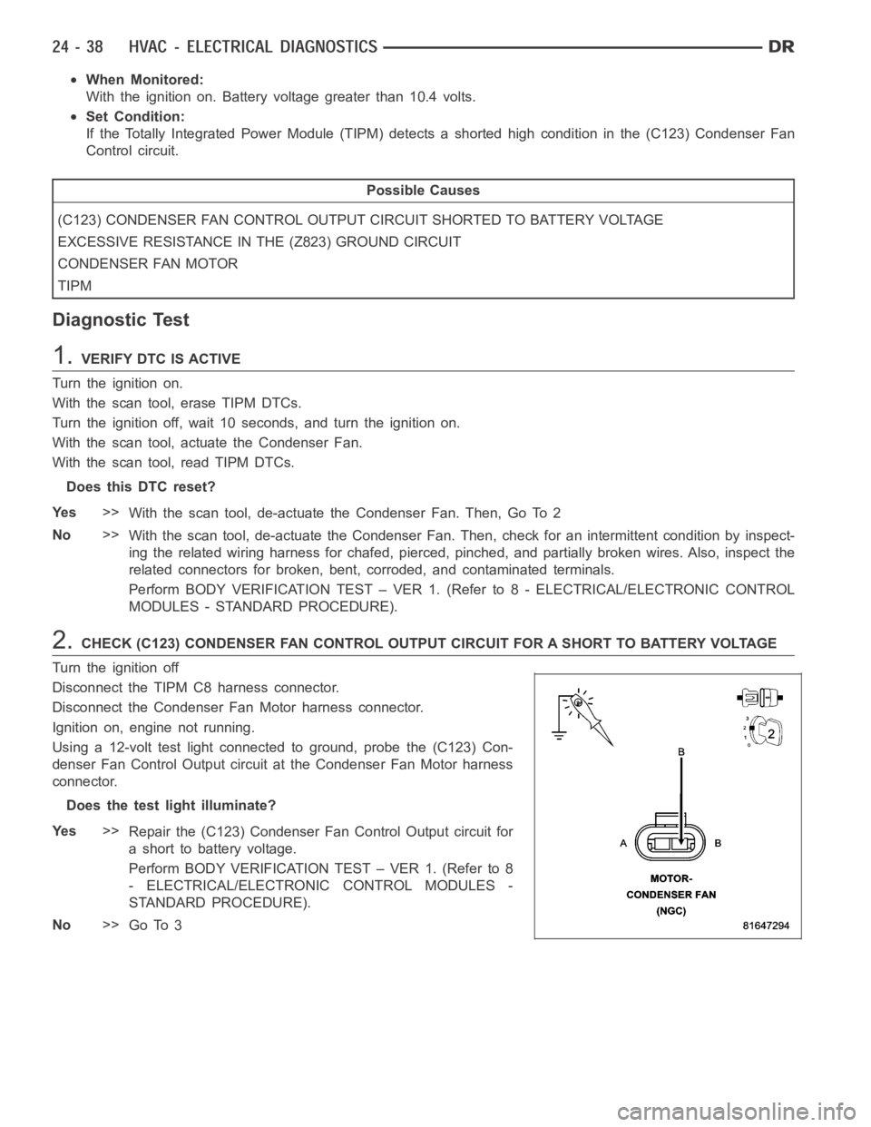
Using a 12-volt test light connected to ground, probe the (C123) Con-
denser Fan Control Output circuit at the Condenser Fan Motor harness
connector.
Does the test light illuminate?
Ye s>>
Repair the (C123) Condenser Fan Control Output circuit for
a short to battery voltage.
Perform BODY VERIFICATION TEST – VER 1. (Refer to 8
- ELECTRICAL/ELECTRONIC CONTROL MODULES -
STANDARD PROCEDURE).
No>>
Go To 3
Page 4880 of 5267
3.CHECK (Z823) GROUND CIRCUIT FOR AN OPEN
Turn the ignition off.
Reconnect the TIPM C8 harness connector.
NOTE: The test light should illuminate brightly. Compare the
brightness to that of a direct connection to the battery.
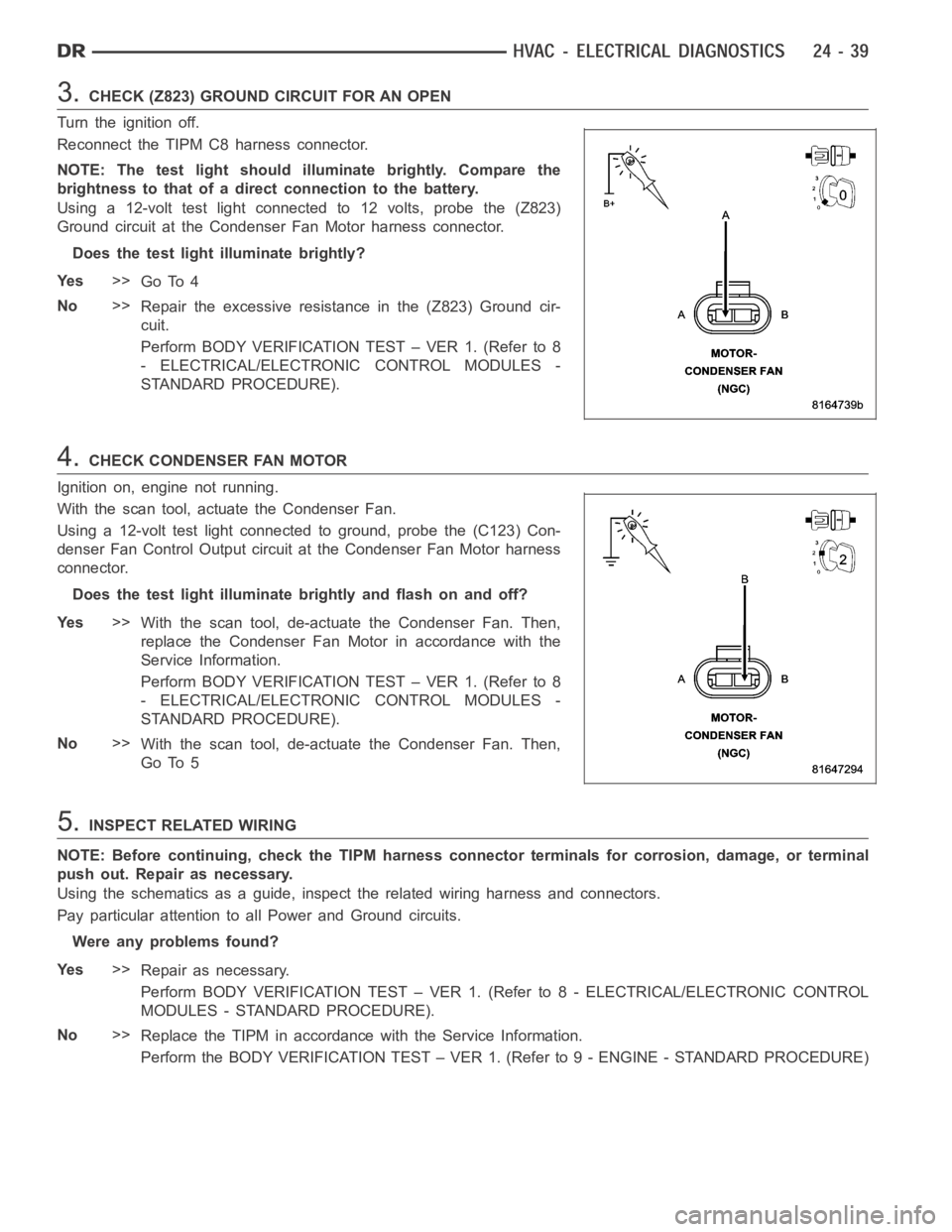
Using a 12-volt test light connected to 12 volts, probe the (Z823)
Ground circuit at the Condenser Fan Motor harness connector.
Does the test light illuminate brightly?
Ye s>>
Go To 4
No>>
Repair the excessive resistance in the (Z823) Ground cir-
cuit.
Perform BODY VERIFICATION TEST – VER 1. (Refer to 8
- ELECTRICAL/ELECTRONIC CONTROL MODULES -
STANDARD PROCEDURE).
4.CHECK CONDENSER FAN MOTOR
Ignition on, engine not running.
With the scan tool, actuate the Condenser Fan.
Using a 12-volt test light connected to ground, probe the (C123) Con-
denser Fan Control Output circuit at the Condenser Fan Motor harness
connector.
Does the test light illuminate brightly and flash on and off?
Ye s>>
With the scan tool, de-actuate the Condenser Fan. Then,
replace the Condenser Fan Motor in accordance with the
Service Information.
Perform BODY VERIFICATION TEST – VER 1. (Refer to 8
- ELECTRICAL/ELECTRONIC CONTROL MODULES -
STANDARD PROCEDURE).
No>>
With the scan tool, de-actuate the Condenser Fan. Then,
Go To 5
5.INSPECT RELATED WIRING
NOTE: Before continuing, check the TIPM harness connector terminals for corrosion, damage, or terminal
push out. Repair as necessary.
Using the schematics as a guide, inspect the related wiring harness and connectors.
Pay particular attention to all Power and Ground circuits.
Were any problems found?
Ye s>>
Repair as necessary.
Perform BODY VERIFICATION TEST – VER 1. (Refer to 8 - ELECTRICAL/ELECTRONIC CONTROL
MODULES - STANDARD PROCEDURE).
No>>
Replace the TIPM in accordance with the Service Information.
Perform the BODY VERIFICATION TEST – VER 1. (Refer to 9 - ENGINE - STANDARD PROCEDURE)
Page 4884 of 5267
When Monitored:
With the ignition on. Battery voltage greater than 10.4 volts. TIPM requesting Condenser Fan operation.
Set Condition:
If the Totally Integrated Power Module (TIPM) detects an open condition inthe (C123) Condenser Fan Control
circuit.
Possible Causes
(C123) CONDENSER FAN CONTROL OUTPUT CIRCUIT OPEN
CONDENSER FAN MOTOR
TIPM
Diagnostic Test
1.VERIFY DTC IS ACTIVE
Turn the ignition on.
With the scan tool, erase TIPM DTCs.
Turn the ignition off, wait 10 seconds, and turn the ignition on.
With the scan tool, actuate the Condenser Fan.
With the scan tool, read TIPM DTCs.
Does this DTC reset?
Ye s>>
With the scan tool, de-actuate the Condenser Fan. Then, Go To 2
No>>
With the scan tool, de-actuate the Condenser Fan. Then, check for an intermittent condition by inspect-
ing the related wiring harness for chafed, pierced, pinched, and partially broken wires. Also, inspect the
related connectors for broken, bent, corroded, and contaminated terminals.
Perform BODY VERIFICATION TEST – VER 1. (Refer to 8 - ELECTRICAL/ELECTRONIC CONTROL
MODULES - STANDARD PROCEDURE).
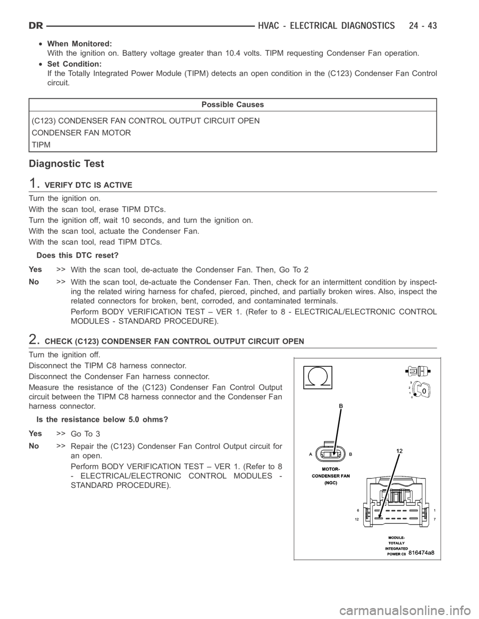
2.CHECK (C123) CONDENSER FAN CONTROL OUTPUT CIRCUIT OPEN
Turn the ignition off.
Disconnect the TIPM C8 harness connector.
Disconnect the Condenser Fan harness connector.
Measure the resistance of the (C123) Condenser Fan Control Output
circuit between the TIPM C8 harness connector and the Condenser Fan
harness connector.
Is the resistance below 5.0 ohms?
Ye s>>
Go To 3
No>>
Repair the (C123) Condenser Fan Control Output circuit for
an open.
Perform BODY VERIFICATION TEST – VER 1. (Refer to 8
- ELECTRICAL/ELECTRONIC CONTROL MODULES -
STANDARD PROCEDURE).
Page 4888 of 5267
3.CHECK THE (F942) FUSED IGNITION SWITCH OUTPUT (RUN-START) CIRCUIT FUNCTION
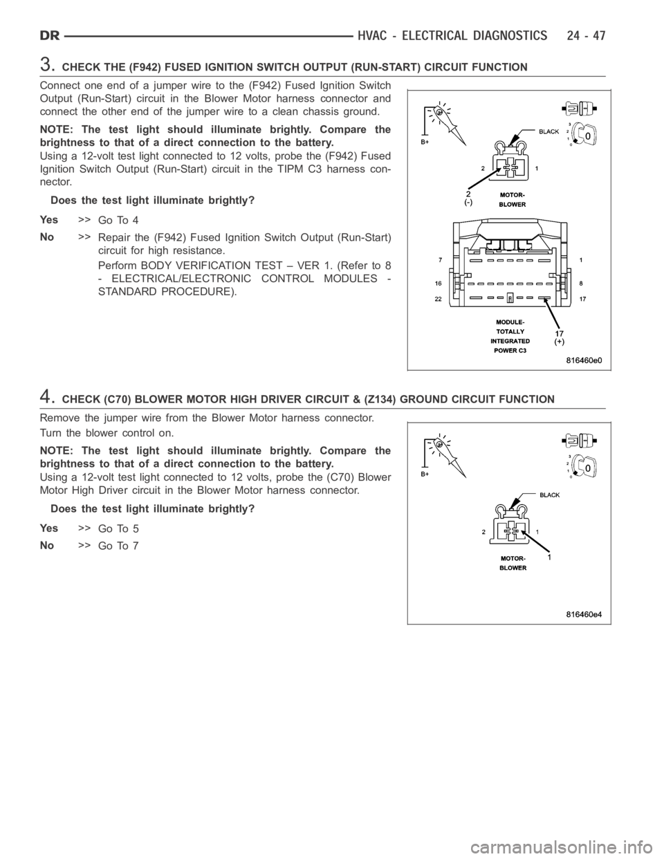
Connect one end of a jumper wire to the (F942) Fused Ignition Switch
Output (Run-Start) circuit in the Blower Motor harness connector and
connect the other end of the jumper wire to a clean chassis ground.
NOTE: The test light should illuminate brightly. Compare the
brightness to that of a direct connection to the battery.
Using a 12-volt test light connected to 12 volts, probe the (F942) Fused
Ignition Switch Output (Run-Start) circuit in the TIPM C3 harness con-
nector.
Does the test light illuminate brightly?
Ye s>>
Go To 4
No>>
Repair the (F942) Fused Ignition Switch Output (Run-Start)
circuit for high resistance.
Perform BODY VERIFICATION TEST – VER 1. (Refer to 8
- ELECTRICAL/ELECTRONIC CONTROL MODULES -
STANDARD PROCEDURE).
4.CHECK (C70) BLOWER MOTOR HIGH DRIVER CIRCUIT & (Z134) GROUND CIRCUIT FUNCTION
Remove the jumper wire from the Blower Motor harness connector.
Turn the blower control on.
NOTE: The test light should illuminate brightly. Compare the
brightness to that of a direct connection to the battery.
Using a 12-volt test light connected to 12 volts, probe the (C70) Blower
Motor High Driver circuit in the Blower Motor harness connector.
Does the test light illuminate brightly?
Ye s>>
Go To 5
No>>
Go To 7
Page 4892 of 5267
When Monitored:
With the ignition on. Battery voltage greater than 10.4 volts. PCM requesting Condenser Fan operation.
Set Condition:
If the Totally Integrated Power Module (TIPM) detects an overcurrent condition on the (C123) Condenser Fan
Control Output circuit.
Possible Causes
TERMINAL DAMAGE OR CORROSION
(Z823) GROUND CIRCUIT HIGH RESISTANCE
(C123) CONDENSER FAN CONTROL OUTPUT CIRCUIT HIGH RESISTANCE
CONDENSER FAN MOTOR
TIPM
Diagnostic Test
1.VERIFY DTC IS ACTIVE
Turn the ignition on.
With the scan tool, erase TIPM DTCs.
Turn the ignition off, wait 10 seconds, and turn the ignition on.
With the scan tool, actuate the Condenser Fan.
With the scan tool, read TIPM DTCs.
Does this DTC reset?
Ye s>>
With the scan tool, de-actuate the Condenser Fan. Then, Go To 2
No>>
With the scan tool, de-actuate the Condenser Fan. Then, check for an intermittent condition by inspect-
ing the related wiring harness for chafed, pierced, pinched, and partially broken wires. Also, inspect the
related connectors for broken, bent, corroded, and contaminated terminals.
Perform BODY VERIFICATION TEST – VER 1. (Refer to 8 - ELECTRICAL/ELECTRONIC CONTROL
MODULES - STANDARD PROCEDURE).
2.INSPECT RELATED WIRING HARNESS & CONNECTORS
Turn the ignition off.
Disconnect the TIPM C8 harness connector.
Disconnect the Condenser Fan Motor harness connector.
Inspect the terminal and connector condition. Check for signs of corrosion build up and damage that would com-
promise the terminal to controller pin connection.
NOTE: Make sure that all in-line connectors are inspected for corrosion and damage.
Visually inspect the wiring harness. Look for any chafed, pierced, pinched or partially broken wires hidden in the
wire insulation.
Were any of the above conditions found?
Ye s>>
Repair or replace as necessary.
Perform BODY VERIFICATION TEST – VER 1. (Refer to 8 - ELECTRICAL/ELECTRONIC CONTROL
MODULES - STANDARD PROCEDURE).
No>>
Go To 3
Page 4893 of 5267
3.CHECK (C123) CONDENSER FAN CONTROL OUTPUT CIRCUIT FOR HIGH RESISTANCE
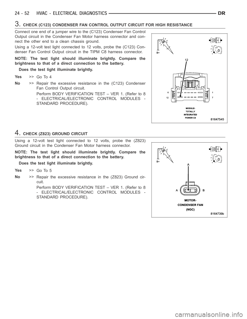
Connect one end of a jumper wire to the (C123) Condenser Fan Control
Output circuit in the Condenser Fan Motor harness connector and con-
nect the other end to a clean chassis ground.
Using a 12-volt test light connected to 12 volts, probe the (C123) Con-
denser Fan Control Output circuit in the TIPM C8 harness connector.
NOTE: The test light should illuminate brightly. Compare the
brightness to that of a direct connection to the battery.
Does the test light illuminate brightly.
Ye s>>
Go To 4
No>>
Repair the excessive resistance in the (C123) Condenser
Fan Control Output circuit.
Perform BODY VERIFICATION TEST – VER 1. (Refer to 8
- ELECTRICAL/ELECTRONIC CONTROL MODULES -
STANDARD PROCEDURE).
4.CHECK (Z823) GROUND CIRCUIT
Using a 12-volt test light connected to 12 volts, probe the (Z823)
Ground circuit in the Condenser Fan Motor harness connector.
NOTE: The test light should illuminate brightly. Compare the
brightness to that of a direct connection to the battery.
Does the test light illuminate brightly.
Ye s>>
Go To 5
No>>
Repair the excessive resistance in the (Z823) Ground cir-
cuit.
Perform BODY VERIFICATION TEST – VER 1. (Refer to 8
- ELECTRICAL/ELECTRONIC CONTROL MODULES -
STANDARD PROCEDURE).