2006 DODGE RAM SRT-10 battery
[x] Cancel search: batteryPage 4902 of 5267
B104C–BLEND DOOR CONTROL CIRCUIT/PERFORMANCE (SINGLE-ZONE)
For a complete wiring diagramRefer to Section 8W.
Theory of Operation
The A/C Heater Control monitors the door driver circuits during actuator operation for shorts to ground, shorts to
battery, and shorts to other door driver circuits. If detected, the A/C Heater Control reports these types of faults as
Control Circuit/Performance DTCs. It is important to note that Control Circuit/Performance DTCs do not indicate
where or what type of short is present and that additional system testing isnecessary to provide more details about
the reported fault.
When Monitored:
With the ignition on.
Set Condition:
If the A/C Heater Control detects a short on any of the door driver circuits while attempting to drive this actua-
tor. This DTC has a maturing time of 5 seconds and a de-maturing time of 10 seconds. If the DTC’s status
changes from active to stored, it will stay in memory for 100 ignition cycles.
Possible Causes
DOOR DRIVER CIRCUIT(S) SHORTED
NOTE:TheDTCmustbeactivefortheresultsofthistesttobevalid.Donotperform this test if the DTC is
stored. Refer to HVAC System Test for stored DTC test procedures.
Diagnostic Test
1.RUN THE ACTUATOR DTC DETECTION TEST
Turn the ignition on.
With the scan tool in HVAC, erase DTCs.
Turn the ignition off, wait 10 seconds, and then turn the ignition on.
With the scan tool, select System Tests and then select Actuator DTC Detection. When the test is complete, select
View DTCs.
Repair
Diagnose and repair the DTC(s). If multiple DTCs are present, beginning with the common circuits, diag-
nose and repair all short high DTCs and then all short low DTCs. Refer to the Table of Contents in this
Section for a complete list of HVAC related symptoms.
Page 4955 of 5267
B1040–PANEL MODE DOOR 1 CONTROL CIRCUIT/PERFORMANCE
For a complete wiring diagramRefer to Section 8W.
Theory of Operation
The A/C Heater Control monitors the door driver circuits during actuator operation for shorts to ground, shorts to
battery, and shorts to other door driver circuits. If detected, the A/C Heater Control reports these types of faults as
Control Circuit/Performance DTCs. It is important to note that Control Circuit/Performance DTCs do not indicate
where or what type of short is present and that additional system testing isnecessary to provide more details about
the reported fault.
When Monitored:
When actuator movement is requested.
Set Condition:
If the A/C Heater Control detects an excessive current draw on any of the door driver circuits while attempting
to drive this actuator. This DTC has a maturing time of 5 seconds and a de-maturing time of 10 seconds. If the
DTC’s status changes from active to stored it will stay in memory for 100 ignition cycles.
Possible Causes
DOOR DRIVER CIRCUIT(S) SHORTED
NOTE:TheDTCmustbeactivefortheresultsofthistesttobevalid.Donotperform this test if the DTC is
stored. Refer to HVAC System Test for stored DTC test procedures.
Diagnostic Test
1.RUN THE ACTUATOR DTC DETECTION TEST
Turn the ignition on.
With the scan tool in HVAC, erase DTCs.
With the scan tool, select System Tests and then select Actuator DTC Detection. When the test is complete, select
View DTCs.
Repair, Dual-Zone System
Diagnose and repair the DTC(s). If multiple DTCs are present, beginning with the passenger blend door,
diagnose and repair all short high DTCs and then all short low DTCs. Refer tothe Table of Contents in
this Section for a complete list of HVAC related symptoms.
Repair, Single-Zone System
Diagnose and repair the DTC(s). If multiple DTCs are present, beginning with the common circuit, diag-
nose and repair all short high DTCs and then all short low DTCs. Refer to the Table of Contents in this
Section for a complete list of HVAC related symptoms.
Page 4980 of 5267
B1046–FLOOR/DEFROST MODE DOORCONTROL CIRCUIT/PERFORMANCE
For a complete wiring diagramRefer to Section 8W.
Theory of Operation
The A/C Heater Control monitors the door driver circuits during actuator operation for shorts to ground, shorts to
battery, and shorts to other door driver circuits. If detected, the A/C Heater Control reports these types of faults as
Control Circuit/Performance DTCs. It is important to note that Control Circuit/Performance DTCs do not indicate
where or what type of short is present and that additional system testing isnecessary to provide more details about
the reported fault.
When Monitored:
When actuator movement is requested.
Set Condition:
If the A/C Heater Control detects an excessive current draw on any of the door driver circuits while attempting
to drive this actuator. This DTC has a maturing time of 5 seconds and a de-maturing time of 10 seconds. If the
DTC’s status changes from active to stored it will stay in memory for 100 ignition cycles.
Possible Causes
DOOR DRIVER CIRCUIT(S) SHORTED
NOTE:TheDTCmustbeactivefortheresultsofthistesttobevalid.Donotperform this test if the DTC is
stored. Refer to HVAC System Test for stored DTC test procedures.
Diagnostic Test
1.RUN THE ACTUATOR DTC DETECTION TEST
Turn the ignition on.
With the scan tool in HVAC, erase DTCs.
With the scan tool, select System Tests and then select Actuator DTC Detection. When the test is complete, select
View DTCs.
Repair, Dual-Zone System
Diagnose and repair the DTC(s). If multiple DTCs are present, beginning with the passenger blend door,
diagnose and repair all short high DTCs and then all short low DTCs. Refer tothe Table of Contents in
this Section for a complete list of HVAC related symptoms.
Repair, Single-Zone System
Diagnose and repair the DTC(s). If multiple DTCs are present, beginning with the common circuit, diag-
nose and repair all short high DTCs and then all short low DTCs. Refer to the Table of Contents in this
Section for a complete list of HVAC related symptoms.
Page 5005 of 5267
B1058–RECIRCULATION DOOR CONTROL CIRCUIT/PERFORMANCE
For a complete wiring diagramRefer to Section 8W.
Theory of Operation
The A/C Heater Control monitors the door driver circuits during actuator operation for shorts to ground, shorts to
battery, and shorts to other door driver circuits. If detected, the A/C Heater Control reports these types of faults as
Control Circuit/Performance DTCs. It is important to note that Control Circuit/Performance DTCs do not indicate
where or what type of short is present and that additional system testing isnecessary to provide more details about
the reported fault.
When Monitored:
When actuator movement is requested.
Set Condition:
If the A/C Heater Control detects an excessive current draw on any of the door driver circuits while attempting
to drive this actuator. This DTC has a maturing time of 5 seconds and a de-maturing time of 10 seconds. If the
DTC’s status changes from active to stored it will stay in memory for 100 ignition cycles.
Possible Causes
DOOR DRIVER CIRCUIT(S) SHORTED
NOTE:TheDTCmustbeactivefortheresultsofthistesttobevalid.Donotperform this test if the DTC is
stored. Refer to HVAC System Test for stored DTC test procedures.
Diagnostic Test
1.RUN THE ACTUATOR DTC DETECTION TEST
Turn the ignition on.
With the scan tool in HVAC, erase DTCs.
With the scan tool, select System Tests and then select Actuator DTC Detection. When the test is complete, select
View DTCs.
Repair, Dual-Zone System
Diagnose and repair the DTC(s). If multiple DTCs are present, beginning with the passenger blend door,
diagnose and repair all short high DTCs and then all short low DTCs. Refer tothe Table of Contents in
this Section for a complete list of HVAC related symptoms.
Repair, Single-Zone System
Diagnose and repair the DTC(s). If multiple DTCs are present, beginning with the common circuit, diag-
nose and repair all short high DTCs and then all short low DTCs. Refer to the Table of Contents in this
Section for a complete list of HVAC related symptoms.
Page 5038 of 5267
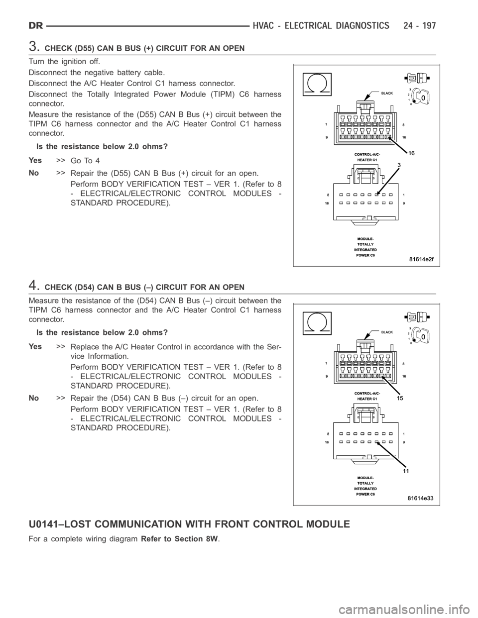
3.CHECK(D55)CANBBUS(+)CIRCUITFORANOPEN
Turn the ignition off.
Disconnect the negative battery cable.
Disconnect the A/C Heater Control C1 harness connector.
Disconnect the Totally Integrated Power Module (TIPM) C6 harness
connector.
Measure the resistance of the (D55) CAN B Bus (+) circuit between the
TIPM C6 harness connector and the A/C Heater Control C1 harness
connector.
Is the resistance below 2.0 ohms?
Ye s>>
Go To 4
No>>
Repair the (D55) CAN B Bus (+) circuit for an open.
Perform BODY VERIFICATION TEST – VER 1. (Refer to 8
- ELECTRICAL/ELECTRONIC CONTROL MODULES -
STANDARD PROCEDURE).
4.CHECK (D54) CAN B BUS (–) CIRCUIT FOR AN OPEN
Measure the resistance of the (D54) CAN B Bus (–) circuit between the
TIPM C6 harness connector and the A/C Heater Control C1 harness
connector.
Is the resistance below 2.0 ohms?
Ye s>>
Replace the A/C Heater Control in accordance with the Ser-
vice Information.
Perform BODY VERIFICATION TEST – VER 1. (Refer to 8
- ELECTRICAL/ELECTRONIC CONTROL MODULES -
STANDARD PROCEDURE).
No>>
Repair the (D54) CAN B Bus (–) circuit for an open.
Perform BODY VERIFICATION TEST – VER 1. (Refer to 8
- ELECTRICAL/ELECTRONIC CONTROL MODULES -
STANDARD PROCEDURE).
U0141–LOST COMMUNICATION WITH FRONT CONTROL MODULE
For a complete wiring diagramRefer to Section 8W.
Page 5044 of 5267
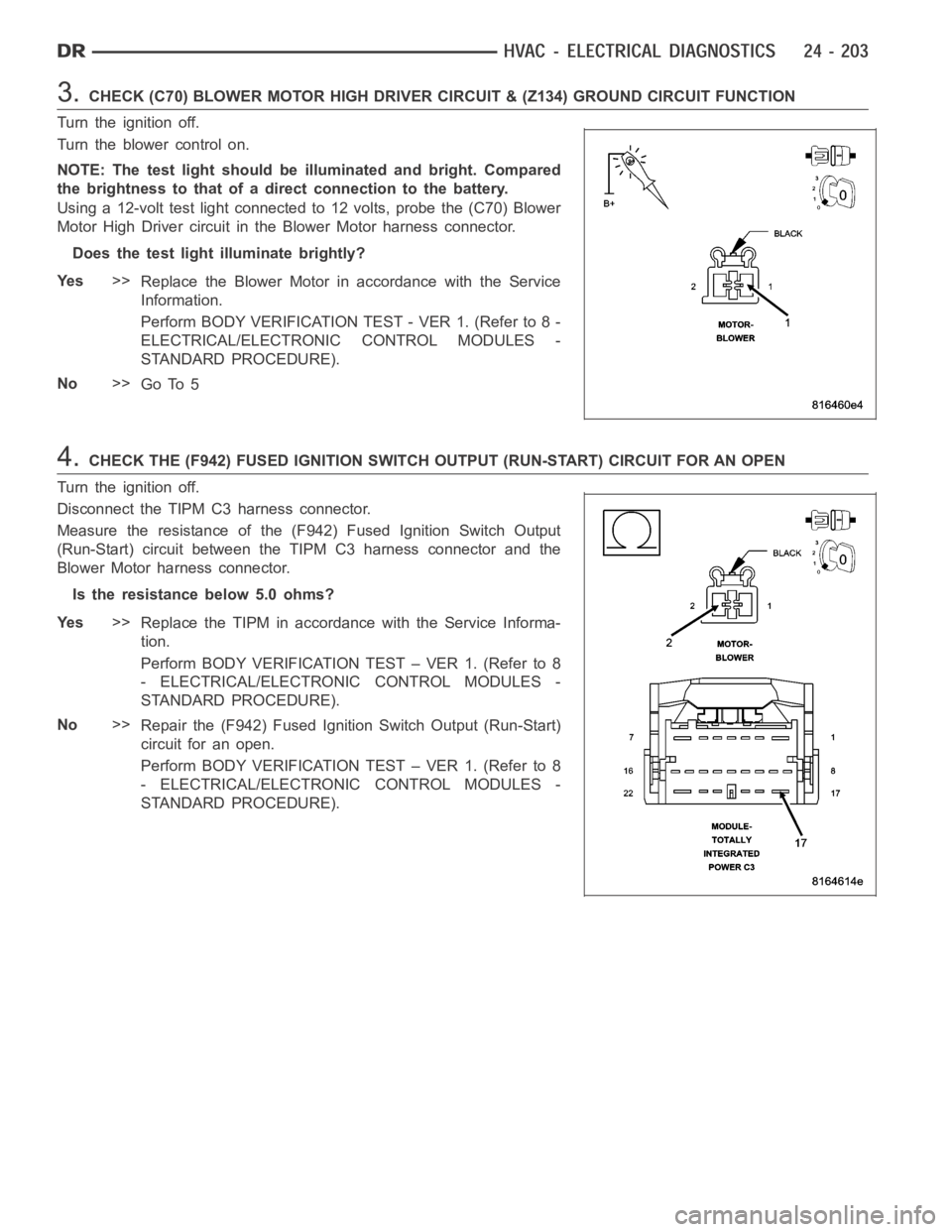
3.CHECK (C70) BLOWER MOTOR HIGH DRIVER CIRCUIT & (Z134) GROUND CIRCUIT FUNCTION
Turn the ignition off.
Turn the blower control on.
NOTE: The test light should be illuminated and bright. Compared
the brightness to that of a direct connection to the battery.
Using a 12-volt test light connected to 12 volts, probe the (C70) Blower
Motor High Driver circuit in the Blower Motor harness connector.
Does the test light illuminate brightly?
Ye s>>
Replace the Blower Motor in accordance with the Service
Information.
Perform BODY VERIFICATION TEST - VER 1. (Refer to 8 -
ELECTRICAL/ELECTRONIC CONTROL MODULES -
STANDARD PROCEDURE).
No>>
Go To 5
4.CHECK THE (F942) FUSED IGNITION SWITCH OUTPUT (RUN-START) CIRCUIT FOR AN OPEN
Turn the ignition off.
Disconnect the TIPM C3 harness connector.
Measure the resistance of the (F942) Fused Ignition Switch Output
(Run-Start) circuit between the TIPM C3 harness connector and the
Blower Motor harness connector.
Is the resistance below 5.0 ohms?
Ye s>>
Replace the TIPM in accordance with the Service Informa-
tion.
Perform BODY VERIFICATION TEST – VER 1. (Refer to 8
- ELECTRICAL/ELECTRONIC CONTROL MODULES -
STANDARD PROCEDURE).
No>>
Repair the (F942) Fused Ignition Switch Output (Run-Start)
circuit for an open.
Perform BODY VERIFICATION TEST – VER 1. (Refer to 8
- ELECTRICAL/ELECTRONIC CONTROL MODULES -
STANDARD PROCEDURE).
Page 5062 of 5267
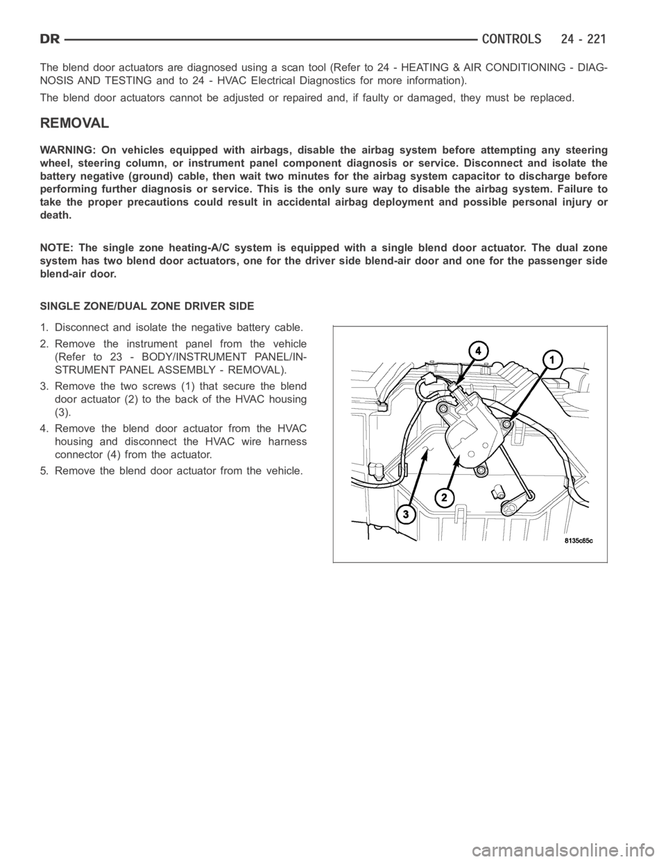
The blend door actuators are diagnosed using a scan tool (Refer to 24 - HEATING & AIR CONDITIONING - DIAG-
NOSIS AND TESTING and to 24 - HVAC Electrical Diagnostics for more information).
The blend door actuators cannot be adjusted or repaired and, if faulty or damaged, they must be replaced.
REMOVAL
WARNING: On vehicles equipped with airbags, disable the airbag system before attempting any steering
wheel, steering column, or instrument panel component diagnosis or service. Disconnect and isolate the
battery negative (ground) cable, then wait two minutes for the airbag system capacitor to discharge before
performing further diagnosis or service. This is the only sure way to disable the airbag system. Failure to
take the proper precautions could result in accidental airbag deploymentand possible personal injury or
death.
NOTE: The single zone heating-A/C system is equipped with a single blend door actuator. The dual zone
system has two blend door actuators, one for the driver side blend-air doorand one for the passenger side
blend-air door.
SINGLE ZONE/DUAL ZONE DRIVER SIDE
1. Disconnect and isolate the negative battery cable.
2. Remove the instrument panel from the vehicle
(Refer to 23 - BODY/INSTRUMENT PANEL/IN-
STRUMENT PANEL ASSEMBLY - REMOVAL).
3. Remove the two screws (1) that secure the blend
door actuator (2) to the back of the HVAC housing
(3).
4. Remove the blend door actuator from the HVAC
housing and disconnect the HVAC wire harness
connector (4) from the actuator.
5. Remove the blend door actuator from the vehicle.
Page 5063 of 5267
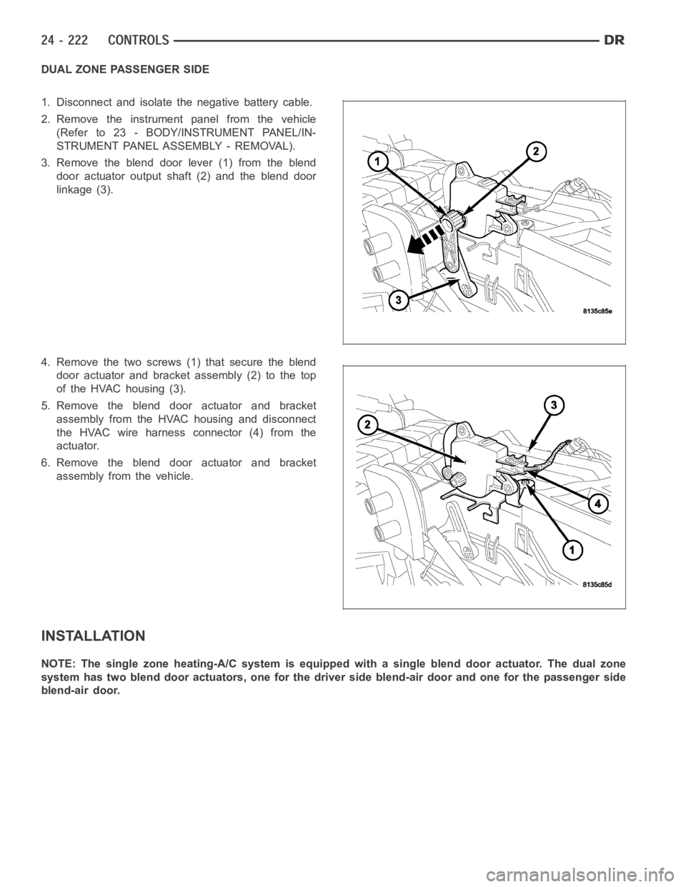
DUAL ZONE PASSENGER SIDE
1. Disconnect and isolate the negative battery cable.
2. Remove the instrument panel from the vehicle
(Refer to 23 - BODY/INSTRUMENT PANEL/IN-
STRUMENT PANEL ASSEMBLY - REMOVAL).
3. Remove the blend door lever (1) from the blend
door actuator output shaft (2) and the blend door
linkage (3).
4. Remove the two screws (1) that secure the blend
door actuator and bracket assembly (2) to the top
of the HVAC housing (3).
5. Remove the blend door actuator and bracket
assembly from the HVAC housing and disconnect
the HVAC wire harness connector (4) from the
actuator.
6. Remove the blend door actuator and bracket
assembly from the vehicle.
INSTALLATION
NOTE: The single zone heating-A/C system is equipped with a single blend door actuator. The dual zone
system has two blend door actuators, one for the driver side blend-air doorand one for the passenger side
blend-air door.