2006 DODGE RAM SRT-10 battery
[x] Cancel search: batteryPage 5119 of 5267
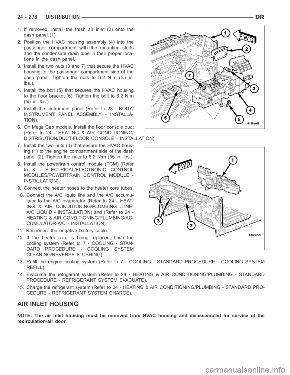
1. If removed, install the fresh air inlet (2) onto the
dash panel (1).
2. Position the HVAC housing assembly (4) into the
passenger compartment with the mounting studs
and the condensate drain tube in their proper loca-
tions in the dash panel.
3. Install the two nuts (3 and 7) that secure the HVAC
housing to the passenger compartment side of the
dash panel. Tighten the nuts to 6.2 Nꞏm (55 in.
lbs.).
4. Install the bolt (5) that secures the HVAC housing
to the floor bracket (6). Tighten the bolt to 6.2 Nꞏm
(55 in. lbs.).
5. Install the instrument panel (Refer to 23 - BODY/
INSTRUMENT PANEL ASSEMBLY - INSTALLA-
TION).
6. On Mega Cab models, install the floor console duct
(Refer to 24 - HEATING & AIR CONDITIONING/
DISTRIBUTION/DUCT-FLOOR CONSOLE - INSTALLATION).
7. Install the two nuts (3) that secure the HVAC hous-
ing (1) to the engine compartment side of the dash
panel (2). Tighten the nuts to 6.2 Nꞏm (55 in. lbs.).
8. Install the powertrain control module (PCM) (Refer
to 8 - ELECTRICAL/ELECTRONIC CONTROL
MODULES/POWERTRAIN CONTROL MODULE -
INSTALLATION).
9. Connect the heater hoses to the heater core tubes.
10. Connect the A/C liquid line and the A/C accumu-
lator to the A/C evaporator (Refer to 24 - HEAT-
ING & AIR CONDITIONING/PLUMBING /LINE-
A/C LIQUID - INSTALLATION) and (Refer to 24 -
HEATING & AIR CONDITIONING/PLUMBING/AC-
CUMULATOR-A/C - INSTALLATION).
11. Reconnect the negative battery cable.
12. If the heater core is being replaced, flush the
coolingsystem(Referto7-COOLING-STAN-
DARD PROCEDURE - COOLING SYSTEM
CLEANING/REVERSE FLUSHING).
13. Refill the engine cooling system (Refer to 7 - COOLING - STANDARD PROCEDURE - COOLING SYSTEM
REFILL).
14. Evacuate the refrigerant system (Refer to 24 - HEATING & AIR CONDITIONING/PLUMBING - STANDARD
PROCEDURE - REFRIGERANT SYSTEM EVACUATE).
15. Charge the refrigerant system (Refer to 24 - HEATING & AIR CONDITIONING/PLUMBING - STANDARD PRO-
CEDURE - REFRIGERANT SYSTEM CHARGE).
AIR INLET HOUSING
NOTE: The air inlet housing must be removed from HVAC housing and disassembled for service of the
recirculation-air door.
Page 5121 of 5267
MOTOR-BLOWER
DESCRIPTION
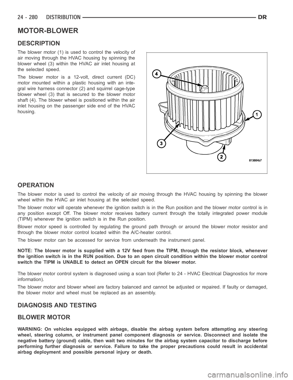
The blower motor (1) is used to control the velocity of
air moving through the HVAC housing by spinning the
blower wheel (3) within the HVAC air inlet housing at
the selected speed.
The blower motor is a 12-volt, direct current (DC)
motormountedwithinaplastichousingwithaninte-
gral wire harness connector (2) and squirrel cage-type
blower wheel (3) that is secured to the blower motor
shaft (4). The blower wheel is positioned within the air
inlet housing on the passenger side end of the HVAC
housing.
OPERATION
The blower motor is used to control the velocity of air moving through the HVAC housing by spinning the blower
wheel within the HVAC air inlet housing at the selected speed.
The blower motor will operate whenever the ignition switch is in the Run position and the blower motor control is in
any position except Off. The blower motor receives battery current through the totally integrated power module
(TIPM) whenever the ignition switch is in the Run position.
Blower motor speed is controlled by regulating the ground path through or around the blower motor resistor and
through the blower motor control located within the A/C-heater control.
The blower motor can be accessed for service from underneath the instrument panel.
NOTE: The blower motor is supplied with a 12V feed from the TIPM, through theresistor block, whenever
the ignition switch is in the RUN position. Due to an open circuit conditionwithin the blower motor control
switch the TIPM is UNABLE to detect an OPEN circuit for the blower motor.
The blower motor control system is diagnosed using a scan tool (Refer to 24 -HVAC Electrical Diagnostics for more
information).
The blower motor and blower wheel are factory balanced and cannot be adjusted or repaired. If faulty or damaged,
the blower motor and wheel must be replaced as an assembly.
DIAGNOSIS AND TESTING
BLOWER MOTOR
WARNING: On vehicles equipped with airbags, disable the airbag system before attempting any steering
wheel, steering column, or instrument panel component diagnosis or service. Disconnect and isolate the
negative battery (ground) cable, then wait two minutes for the airbag system capacitor to discharge before
performing further diagnosis or service. Failure to take the proper precautions could result in accidental
airbag deployment and possible personal injury or death.
Page 5122 of 5267
NOTE: The blower motor is supplied with a 12V feed from the TIPM, through theresistor block, whenever
the ignition switch is in the RUN position. Due to an open circuit conditionwithin the blower motor control
switch the TIPM is UNABLE to detect an OPEN circuit for the blower motor.
To determine if an open condition exists within the blower motor circuit wiring, it is necessary to disconnect the
negative battery cable and check for continuity within the blower motor circuits using an ohmmeter. For circuit
descriptions and diagrams, refer to Air Conditioning/Heater in Group 8W -Wiring Diagrams.
OPERATION
Possible causes of the blower motor not operating include:
Faulty blower motor
Faulty blower motor circuit wiring or wire harness connectors
Faulty blower motor control
Possible causes of the blower motor not operating in one or more speeds include:
Faulty blower motor resistor
Faulty blower motor circuit wiring or wire harness connectors
Faulty blower motor control
VIBRATION
Possible causes of blower motor vibration include:
Improper blower motor mounting
Improper blower wheel mounting
Deformed blower wheel
Out of balance blower wheel due to foreign material in the wheel
Faulty blower motor
NOISE
To determine if the blower motor is the source of the noise, simply switch the blower motor from Off to On. To verify
that the blower motor is the source of the noise, unplug the blower motor wire harness connector and operate the
heating-A/C system. If the noise goes away, possible causes include:
Foreign material in the HVAC air inlet housing
Improper blower motor mounting
Improper blower wheel mounting
Faulty blower motor
Page 5123 of 5267
REMOVAL
NOTE: The blower motor is located on the passen-
ger side of the vehicle under the instrument panel.
The blower motor can be removed from the vehi-
cle without having to remove the HVAC housing.
1. Disconnect and isolate the negative battery cable.
2. Remove the passenger side cowl trim panel (Refer
to 23 - BODY/INTERIOR/COWL TRIM PANEL -
REMOVAL).
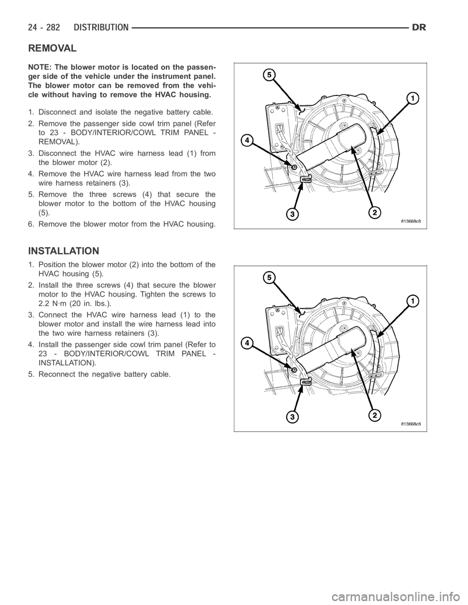
3. Disconnect the HVAC wire harness lead (1) from
the blower motor (2).
4. Remove the HVAC wire harness lead from the two
wire harness retainers (3).
5. Remove the three screws (4) that secure the
blower motor to the bottom of the HVAC housing
(5).
6. Remove the blower motor from the HVAC housing.
INSTALLATION
1. Position the blower motor (2) into the bottom of the
HVAC housing (5).
2. Install the three screws (4) that secure the blower
motor to the HVAC housing. Tighten the screws to
2.2 Nꞏm (20 in. lbs.).
3. Connect the HVAC wire harness lead (1) to the
blower motor and install the wire harness lead into
the two wire harness retainers (3).
4. Install the passenger side cowl trim panel (Refer to
23 - BODY/INTERIOR/COWL TRIM PANEL -
INSTALLATION).
5. Reconnect the negative battery cable.
Page 5134 of 5267
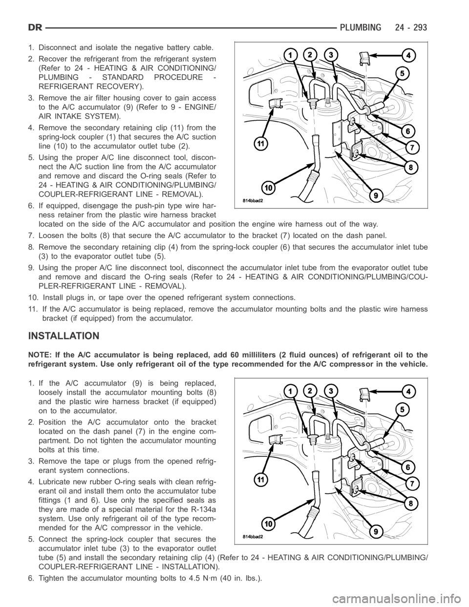
1. Disconnect and isolate the negative battery cable.
2. Recover the refrigerant from the refrigerant system
(Refer to 24 - HEATING & AIR CONDITIONING/
PLUMBING - STANDARD PROCEDURE -
REFRIGERANT RECOVERY).
3. Remove the air filter housing cover to gain access
to the A/C accumulator (9) (Refer to 9 - ENGINE/
AIR INTAKE SYSTEM).
4. Remove the secondary retaining clip (11) from the
spring-lock coupler (1) that secures the A/C suction
line (10) to the accumulator outlet tube (2).
5. Using the proper A/C line disconnect tool, discon-
nect the A/C suction line from the A/C accumulator
and remove and discard the O-ring seals (Refer to
24 - HEATING & AIR CONDITIONING/PLUMBING/
COUPLER-REFRIGERANT LINE - REMOVAL).
6. If equipped, disengage the push-pin type wire har-
ness retainer from the plastic wire harness bracket
located on the side of the A/C accumulator and position the engine wire harness out of the way.
7. Loosen the bolts (8) that secure the A/C accumulator to the bracket (7) located on the dash panel.
8. Remove the secondary retaining clip (4) from the spring-lock coupler (6) that secures the accumulator inlet tube
(3) to the evaporator outlet tube (5).
9. Using the proper A/C line disconnect tool, disconnect the accumulator inlet tube from the evaporator outlet tube
and remove and discard the O-ring seals (Refer to 24 - HEATING & AIR CONDITIONING/PLUMBING/COU-
PLER-REFRIGERANT LINE - REMOVAL).
10. Install plugs in, or tape over the opened refrigerant system connections.
11. If the A/C accumulator is being replaced, remove the accumulator mounting bolts and the plastic wire harness
bracket (if equipped) from the accumulator.
INSTALLATION
NOTE: If the A/C accumulator is being replaced, add 60 milliliters (2 fluidounces) of refrigerant oil to the
refrigerant system. Use only refrigerant oil of the type recommended for the A/C compressor in the vehicle.
1. If the A/C accumulator (9) is being replaced,
loosely install the accumulator mounting bolts (8)
and the plastic wire harness bracket (if equipped)
on to the accumulator.
2. Position the A/C accumulator onto the bracket
located on the dash panel (7) in the engine com-
partment. Do not tighten the accumulator mounting
bolts at this time.
3. Remove the tape or plugs from the opened refrig-
erant system connections.
4. Lubricate new rubber O-ring seals with clean refrig-
erant oil and install them onto the accumulator tube
fittings (1 and 6). Use only the specified seals as
they are made of a special material for the R-134a
system. Use only refrigerant oil of the type recom-
mended for the A/C compressor in the vehicle.
5. Connect the spring-lock coupler that secures the
accumulator inlet tube (3) to the evaporator outlet
tube (5) and install the secondary retaining clip (4) (Refer to 24 - HEATING& AIR CONDITIONING/PLUMBING/
COUPLER-REFRIGERANT LINE - INSTALLATION).
6. Tighten the accumulator mounting bolts to 4.5 Nꞏm (40 in. lbs.).
Page 5135 of 5267
7. If equipped, engage the engine wire harness retaining clip to the plastic wire harness bracket located on the side
of the A/C accumulator.
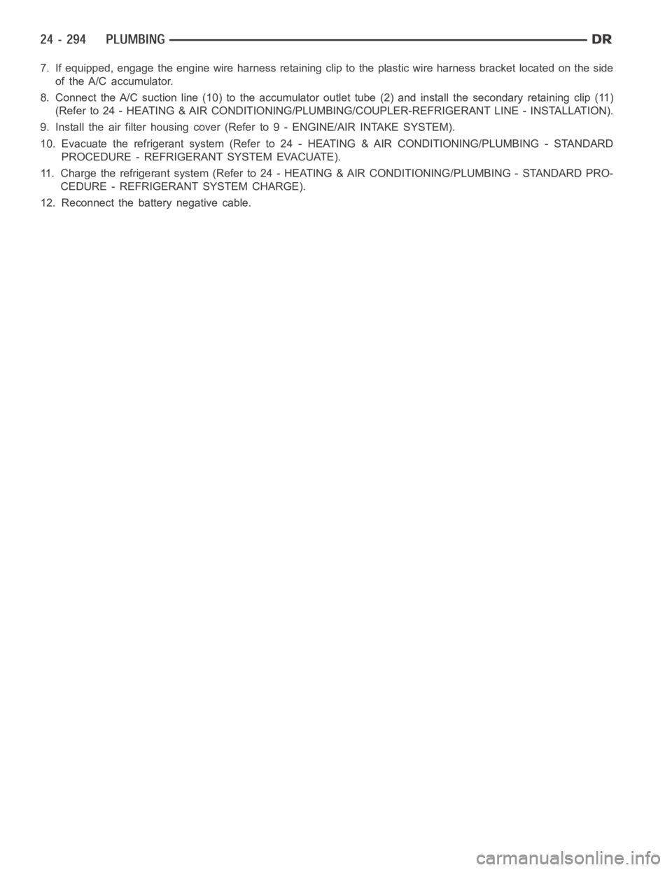
8. Connect the A/C suction line (10) to the accumulator outlet tube (2) and install the secondaryretaining clip (11)
(Refer to 24 - HEATING & AIR CONDITIONING/PLUMBING/COUPLER-REFRIGERANTLINE - INSTALLATION).
9. Install the air filter housing cover (Refer to 9 - ENGINE/AIR INTAKE SYSTEM).
10. Evacuate the refrigerant system (Refer to 24 - HEATING & AIR CONDITIONING/PLUMBING - STANDARD
PROCEDURE - REFRIGERANT SYSTEM EVACUATE).
11. Charge the refrigerant system (Refer to 24 - HEATING & AIR CONDITIONING/PLUMBING - STANDARD PRO-
CEDURE - REFRIGERANT SYSTEM CHARGE).
12. Reconnect the battery negative cable.
Page 5138 of 5267
1. Recover the refrigerant from the refrigerant system
(Refer to 24 - HEATING & AIR CONDITIONING/
PLUMBING - STANDARD PROCEDURE -
REFRIGERANT SYSTEM RECOVERY).
2. Disconnect and isolate the negative battery cable.
3. Remove the accessory drive belt (Refer to 7 -
COOLING/ACCESSORY DRIVE/BELTS-DRIVE -
REMOVAL).
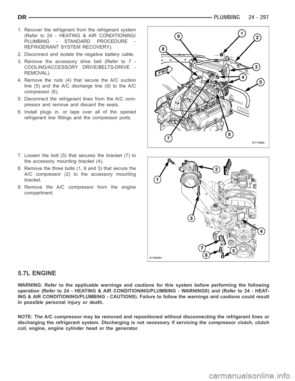
4. Remove the nuts (4) that secure the A/C suction
line (5) and the A/C discharge line (9) to the A/C
compressor (6).
5. Disconnect the refrigerant lines from the A/C com-
pressor and remove and discard the seals.
6. Install plugs in, or tape over all of the opened
refrigerant line fittings and the compressor ports.
7. Loosen the bolt (5) that secures the bracket (7) to
the accessory mounting bracket (4).
8. Remove the three bolts (1, 6 and 3) that secure the
A/C compressor (2) to the accessory mounting
bracket.
9. Remove the A/C compressor from the engine
compartment.
5.7L ENGINE
WARNING: Refer to the applicable warnings and cautions for this system before performing the following
operation (Refer to 24 - HEATING & AIR CONDITIONING/PLUMBING - WARNINGS) and (Refer to 24 - HEAT-
ING & AIR CONDITIONING/PLUMBING - CAUTIONS). Failure to follow the warnings and cautions could result
in possible personal injury or death.
NOTE: The A/C compressor may be removed and repositioned without disconnecting the refrigerant lines or
discharging the refrigerant system. Discharging is not necessary if servicing the compressor clutch, clutch
coil, engine, engine cylinder head or the generator.
Page 5139 of 5267
1. Recover the refrigerant from the refrigerant system
(Refer to 24 - HEATING & AIR CONDITIONING/
PLUMBING - STANDARD PROCEDURE -
REFRIGERANT SYSTEM RECOVERY).
2. Disconnect and isolate the negative battery cable.
3. Remove the accessory drive belt (Refer to 7 -
COOLING/ACCESSORY DRIVE/BELTS-DRIVE -
REMOVAL).
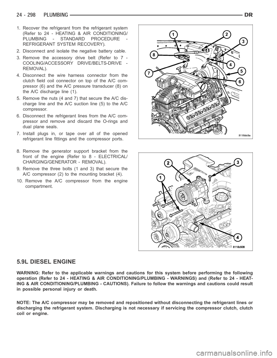
4. Disconnect the wire harness connector from the
clutch field coil connector on top of the A/C com-
pressor (6) and the A/C pressure transducer (8) on
the A/C discharge line (1).
5. Remove the nuts (4 and 7) that secure the A/C dis-
charge line and the A/C suction line (5) to the A/C
compressor.
6. Disconnect the refrigerant lines from the A/C com-
pressor and remove and discard the O-rings and
dual plane seals.
7. Install plugs in, or tape over all of the opened
refrigerant line fittings and the compressor ports.
8. Remove the generator support bracket from the
front of the engine (Refer to 8 - ELECTRICAL/
CHARGING/GENERATOR - REMOVAL).
9. Remove the three bolts (1 and 3) that secure the
A/C compressor (2) to the mounting bracket (4).
10. Remove the A/C compressor from the engine
compartment.
5.9L DIESEL ENGINE
WARNING: Refer to the applicable warnings and cautions for this system before performing the following
operation (Refer to 24 - HEATING & AIR CONDITIONING/PLUMBING - WARNINGS) and (Refer to 24 - HEAT-
ING & AIR CONDITIONING/PLUMBING - CAUTIONS). Failure to follow the warnings and cautions could result
in possible personal injury or death.
NOTE: The A/C compressor may be removed and repositioned without disconnecting the refrigerant lines or
discharging the refrigerant system. Discharging is not necessary if servicing the compressor clutch, clutch
coil or engine.