2006 DODGE RAM SRT-10 battery
[x] Cancel search: batteryPage 5181 of 5267
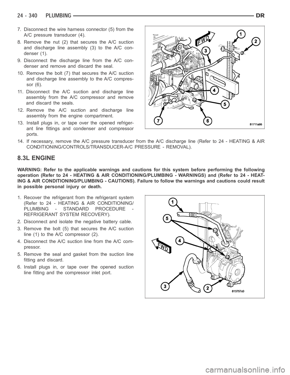
7. Disconnect the wire harness connector (5) from the
A/C pressure transducer (4).
8. Remove the nut (2) that secures the A/C suction
and discharge line assembly (3) to the A/C con-
denser (1).
9. Disconnect the discharge line from the A/C con-
denser and remove and discard the seal.
10. Remove the bolt (7) that secures the A/C suction
and discharge line assembly to the A/C compres-
sor (6).
11. Disconnect the A/C suction and discharge line
assembly from the A/C compressor and remove
and discard the seals.
12. Remove the A/C suction and discharge line
assembly from the engine compartment.
13. Install plugs in, or tape over the opened refriger-
ant line fittings and condenser and compressor
ports.
14. If necessary, remove the A/C pressure transducer from the A/C dischargeline(Referto24-HEATING&AIR
CONDITIONING/CONTROLS/TRANSDUCER-A/C PRESSURE - REMOVAL).
8.3L ENGINE
WARNING: Refer to the applicable warnings and cautions for this system before performing the following
operation (Refer to 24 - HEATING & AIR CONDITIONING/PLUMBING - WARNINGS) and (Refer to 24 - HEAT-
ING & AIR CONDITIONING/PLUMBING - CAUTIONS). Failure to follow the warnings and cautions could result
in possible personal injury or death.
1. Recover the refrigerant from the refrigerant system
(Refer to 24 - HEATING & AIR CONDITIONING/
PLUMBING - STANDARD PROCEDURE -
REFRIGERANT SYSTEM RECOVERY).
2. Disconnect and isolate the negative battery cable.
3. Remove the bolt (5) that secures the A/C suction
line (1) to the A/C compressor (2).
4. Disconnect the A/C suction line from the A/C com-
pressor.
5. Remove the seal and gasket from the suction line
fitting and discard.
6. Install plugs in, or tape over the opened suction
line fitting and the compressor inlet port.
Page 5183 of 5267
INSTALLATION
3.7L/4.7L ENGINES
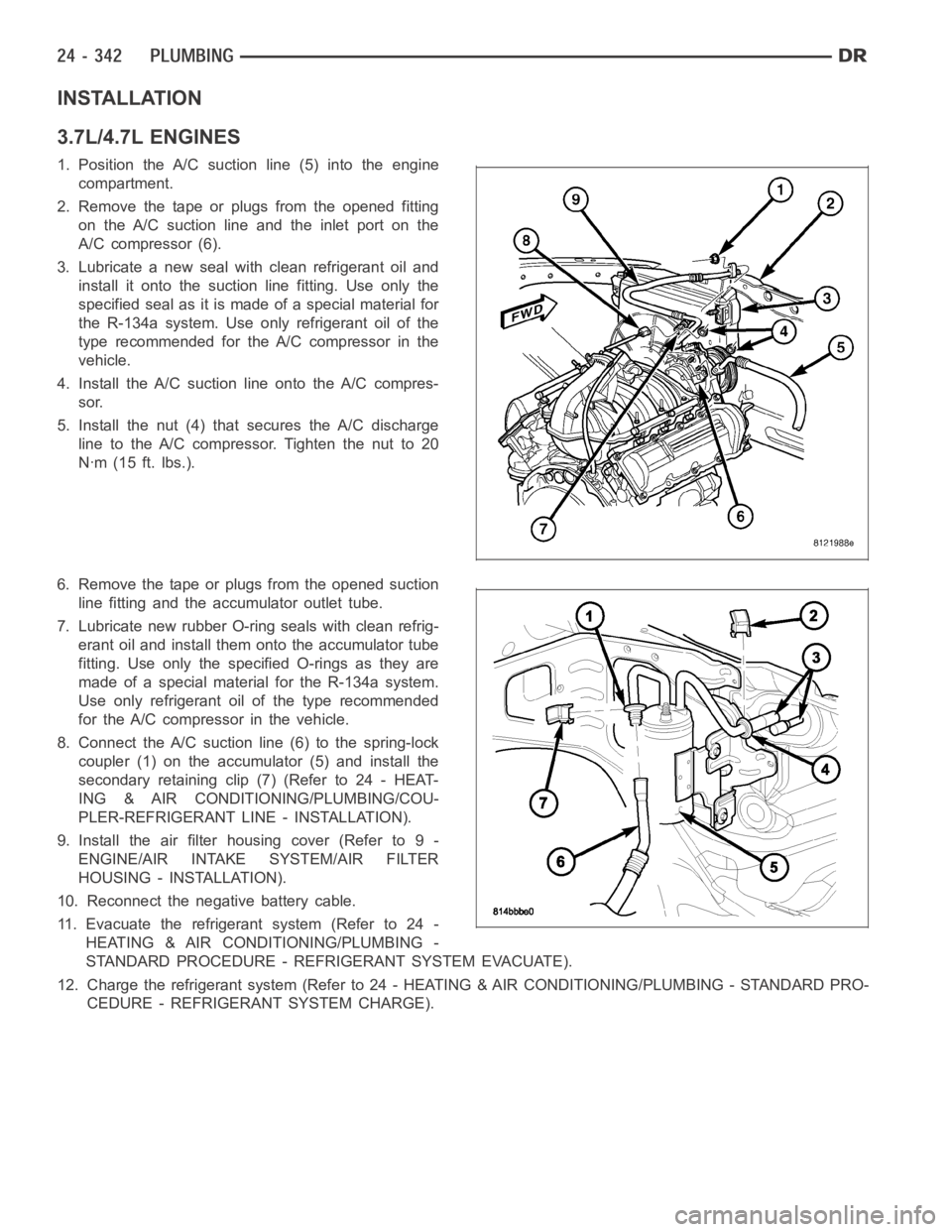
1. Position the A/C suction line (5) into the engine
compartment.
2. Remove the tape or plugs from the opened fitting
on the A/C suction line and the inlet port on the
A/C compressor (6).
3. Lubricate a new seal with clean refrigerant oil and
install it onto the suction line fitting. Use only the
specified seal as it is made of a special material for
the R-134a system. Use only refrigerant oil of the
type recommended for the A/C compressor in the
vehicle.
4. Install the A/C suction line onto the A/C compres-
sor.
5. Install the nut (4) that secures the A/C discharge
line to the A/C compressor. Tighten the nut to 20
Nꞏm (15 ft. lbs.).
6. Remove the tape or plugs from the opened suction
line fitting and the accumulator outlet tube.
7. Lubricate new rubber O-ring seals with clean refrig-
erant oil and install them onto the accumulator tube
fitting. Use only the specified O-rings as they are
made of a special material for the R-134a system.
Use only refrigerant oil of the type recommended
for the A/C compressor in the vehicle.
8. Connect the A/C suctionline (6) to the spring-lock
coupler (1) on the accumulator (5) and install the
secondary retaining clip (7) (Refer to 24 - HEAT-
ING & AIR CONDITIONING/PLUMBING/COU-
PLER-REFRIGERANT LINE - INSTALLATION).
9. Install the air filter housing cover (Refer to 9 -
ENGINE/AIR INTAKE SYSTEM/AIR FILTER
HOUSING - INSTALLATION).
10. Reconnect the negative battery cable.
11. Evacuate the refrigerant system (Refer to 24 -
HEATING & AIR CONDITIONING/PLUMBING -
STANDARD PROCEDURE - REFRIGERANT SYSTEM EVACUATE).
12. Charge the refrigerant system (Refer to 24 - HEATING & AIR CONDITIONING/PLUMBING - STANDARD PRO-
CEDURE - REFRIGERANT SYSTEM CHARGE).
Page 5184 of 5267
5.7L ENGINE
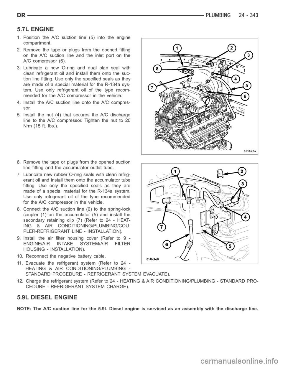
1. Position the A/C suction line (5) into the engine
compartment.
2. Remove the tape or plugs from the opened fitting
on the A/C suction line and the inlet port on the
A/C compressor (6).
3. Lubricate a new O-ring and dual plan seal with
clean refrigerant oil and install them onto the suc-
tion line fitting. Use only the specified seals as they
are made of a special material for the R-134a sys-
tem. Use only refrigerant oil of the type recom-
mended for the A/C compressor in the vehicle.
4. Install the A/C suction line onto the A/C compres-
sor.
5. Install the nut (4) that secures the A/C discharge
line to the A/C compressor. Tighten the nut to 20
Nꞏm (15 ft. lbs.).
6. Remove the tape or plugs from the opened suction
line fitting and the accumulator outlet tube.
7. Lubricate new rubber O-ring seals with clean refrig-
erant oil and install them onto the accumulator tube
fitting. Use only the specified seals as they are
made of a special material for the R-134a system.
Use only refrigerant oil of the type recommended
for the A/C compressor in the vehicle.
8. Connect the A/C suctionline (6) to the spring-lock
coupler (1) on the accumulator (5) and install the
secondary retaining clip (7) (Refer to 24 - HEAT-
ING & AIR CONDITIONING/PLUMBING/COU-
PLER-REFRIGERANT LINE - INSTALLATION).
9. Install the air filter housing cover (Refer to 9 -
ENGINE/AIR INTAKE SYSTEM/AIR FILTER
HOUSING - INSTALLATION).
10. Reconnect the negative battery cable.
11. Evacuate the refrigerant system (Refer to 24 -
HEATING & AIR CONDITIONING/PLUMBING -
STANDARD PROCEDURE - REFRIGERANT SYSTEM EVACUATE).
12. Charge the refrigerant system (Refer to 24 - HEATING & AIR CONDITIONING/PLUMBING - STANDARD PRO-
CEDURE - REFRIGERANT SYSTEM CHARGE).
5.9L DIESEL ENGINE
NOTE: The A/C suction line for the 5.9L Diesel engine is serviced as an assembly with the discharge line.
Page 5185 of 5267
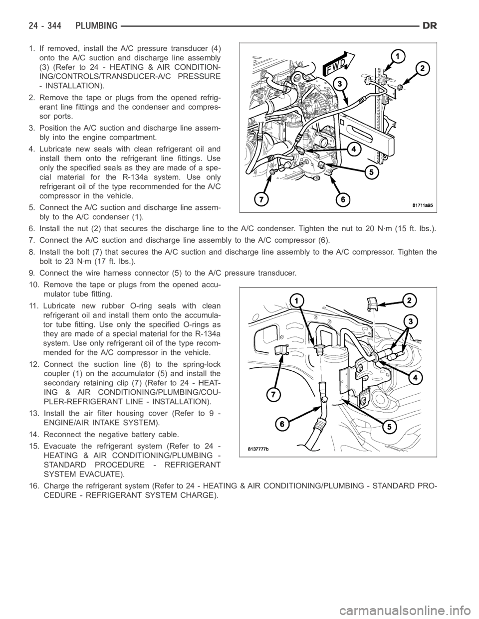
1. If removed, install the A/C pressure transducer (4)
onto the A/C suction and discharge line assembly
(3)(Referto24-HEATING&AIRCONDITION-
ING/CONTROLS/TRANSDUCER-A/C PRESSURE
- INSTALLATION).
2. Remove the tape or plugs from the opened refrig-
erant line fittings and the condenser and compres-
sor ports.
3. Position the A/C suction and discharge line assem-
bly into the engine compartment.
4. Lubricate new seals with clean refrigerant oil and
install them onto the refrigerant line fittings. Use
only the specified seals as they are made of a spe-
cial material for the R-134a system. Use only
refrigerant oil of the type recommended for the A/C
compressor in the vehicle.
5. Connect the A/C suction and discharge line assem-
bly to the A/C condenser (1).
6. Install the nut (2) that secures the discharge line to the A/C condenser.Tighten the nut to 20 Nꞏm (15 ft. lbs.).
7. Connect the A/C suction and discharge line assembly to the A/C compressor(6).
8. Install the bolt (7) that secures the A/C suction and discharge line assembly to the A/C compressor. Tighten the
boltto23Nꞏm(17ft.lbs.).
9. Connect the wire harness connector (5) to the A/C pressure transducer.
10. Remove the tape or plugs from the opened accu-
mulator tube fitting.
11. Lubricate new rubber O-ring seals with clean
refrigerant oil and install them onto the accumula-
tor tube fitting. Use only the specified O-rings as
they are made of a special material for the R-134a
system. Use only refrigerant oil of the type recom-
mended for the A/C compressor in the vehicle.
12. Connect the suction line (6) to the spring-lock
coupler (1) on the accumulator (5) and install the
secondary retaining clip (7) (Refer to 24 - HEAT-
ING & AIR CONDITIONING/PLUMBING/COU-
PLER-REFRIGERANT LINE - INSTALLATION).
13. Install the air filter housing cover (Refer to 9 -
ENGINE/AIR INTAKE SYSTEM).
14. Reconnect the negative battery cable.
15. Evacuate the refrigerant system (Refer to 24 -
HEATING & AIR CONDITIONING/PLUMBING -
STANDARD PROCEDURE - REFRIGERANT
SYSTEM EVACUATE).
16. Charge the refrigerant system (Refer to 24 - HEATING & AIR CONDITIONING/PLUMBING - STANDARD PRO-
CEDURE - REFRIGERANT SYSTEM CHARGE).
Page 5187 of 5267
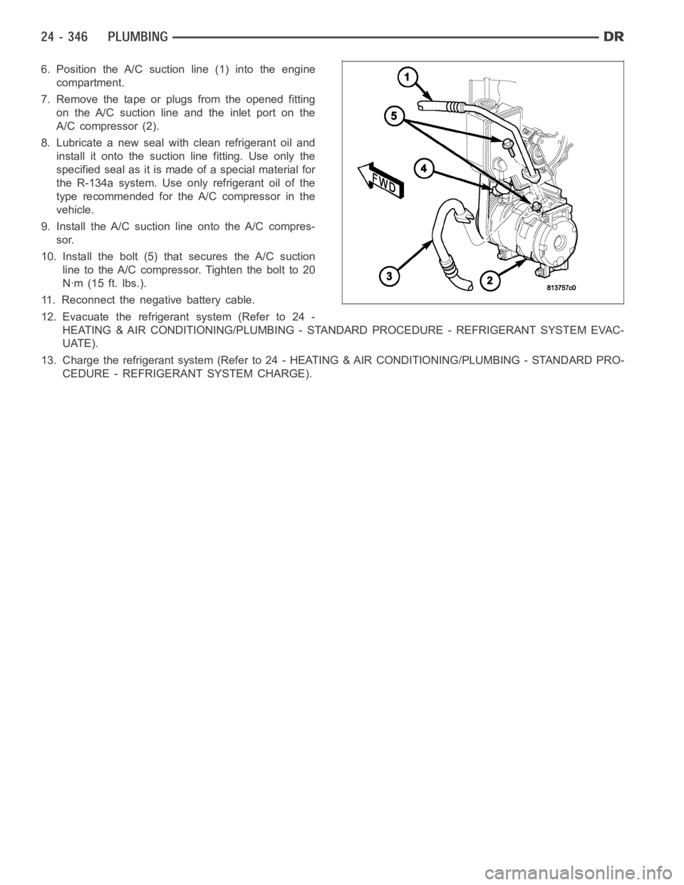
6. Position the A/C suction line (1) into the engine
compartment.
7. Remove the tape or plugs from the opened fitting
on the A/C suction line and the inlet port on the
A/C compressor (2).
8. Lubricate a new seal with clean refrigerant oil and
install it onto the suction line fitting. Use only the
specified seal as it is made of a special material for
the R-134a system. Use only refrigerant oil of the
type recommended for the A/C compressor in the
vehicle.
9. Install the A/C suction line onto the A/C compres-
sor.
10. Install the bolt (5) that secures the A/C suction
line to the A/C compressor. Tighten the bolt to 20
Nꞏm (15 ft. lbs.).
11. Reconnect the negative battery cable.
12. Evacuate the refrigerant system (Refer to 24 -
HEATING & AIR CONDITIONING/PLUMBING - STANDARD PROCEDURE - REFRIGERANT SYSTEM EVAC-
UATE).
13. Charge the refrigerant system (Refer to 24 - HEATING & AIR CONDITIONING/PLUMBING - STANDARD PRO-
CEDURE - REFRIGERANT SYSTEM CHARGE).
Page 5200 of 5267
If the MIL is ON and a DTC was set by the Fuel Monitor or Misfire Monitor (both continuous monitors), the
vehicle must be operated in the Similar Condition Window for a specified amount of time.
If the MIL is ON and a DTC was set by a Task Manager commanded once-per-trip monitor (such as the Oxy-
gen Sensor Monitor, Catalyst Monitor, Purge Flow Monitor, Leak DetectionPump Monitor, EGR Monitor or
Oxygen Sensor Heater Monitor), a good trip is when the monitor is passed on the next start-up.
If the MIL is ON and any other emissions DTC was set (not an OBD II monitor), a good trip occurs when the
Oxygen Sensor Monitor and Catalyst Monitor have been completed, or two minutes of engine run time if the
Oxygen Sensor Monitor and Catalyst Monitor have been stopped from running.
Fuel System Good Trip
To count a good trip (three required) and turn off the MIL, the following conditions must occur:
Engine in closed loop
Operating in Similar Conditions Window
Short Term multiplied by Long Term less than threshold
Less than threshold for a predetermined time
If all of the previous criteria are met, the PCM will count a good trip (threerequired) and turn off the MIL.
Misfire Good Trip
If the following conditions are met the PCM will count one good trip (three required) in order to turn off the MIL:
Operating in Similar Condition Window
1000 engine revolutions with no misfire
Warm-Up Cycles
Once the MIL has been extinguished by the Good Trip Counter, the PCM automatically switches to a Warm-Up
CycleCounterthatcanbeviewedontheDRBIII.Warm-UpCyclesareusedtoerase DTCs and Freeze Frames.
Forty Warm-Up cycles must occur in order for the PCM to self-erase a DTC and Freeze Frame. A Warm-Up Cycle
is defined as follows:
Engine coolant temperature must start below and rise above 160° F (71.1°C).
Engine coolant temperature must rise by 40° F (4.4°C)
No further faults occur
Freeze Frame Data Storage
Once a failure occurs, the Task Manager records several engine operating conditions and stores it in a Freeze
Frame. The Freeze Frame is considered one frame of information taken by an on-board data recorder. When a fault
occurs, the PCM stores the input data from various sensors so that technicians can determine under what vehicle
operating conditions the failure occurred.
The data stored in Freeze Frame is usually recorded when a system fails the first time for two trip faults. Freeze
Frame data will only be overwritten by a different fault with a higher priority.
CAUTION: Erasing DTCs, either with the DRB III or by disconnecting the battery, also clears all Freeze
Frame data.
Similar Conditions Window
The Similar Conditions Window displays information about engine operation during a monitor. Absolute MAP (engine
load) and Engine RPM are stored in this window when a failure occurs. There are two different Similar conditions
Windows: Fuel System and Misfire.
FUEL SYSTEM
Fuel System Similar Conditions Window— An indicator that ’Absolute MAP When Fuel Sys Fail’ and ’RPM
When Fuel Sys Failed’ are all in the same range when the failure occurred. Indicated by switching from ’NO’
to ’YES’.
Absolute MAP When Fuel Sys Fail— The stored MAP reading at the time of failure. Informs the user at
what engine load the failure occurred.
Absolute MAP— A live reading of engine load to aid the user in accessing the Similar Conditions Window.
RPM When Fuel Sys Fail— The stored RPM reading at the time of failure. Informs the user at what engine
RPM the failure occurred.
Page 5213 of 5267
PUMP-NATURAL VAC LEAK DETECTION
DESCRIPTION
Vehicles equipped with an NGC Powertrain Control Module (PCM) use a Natural Vacuum Leak Detection (NVLD)
pump and system. Vehicles equipped with a JTEC PCM use an LDP (Leak Detection Pump). Refer to Leak Detec-
tion Pump (LDP) for additional information.
The NVLD pump is located in the same area as the leak detection pump. Refer toNVLD Removal / Installation for
additional information.
OPERATION
The Natural Vacuum Leak Detection (NVLD) system is the next generation evaporative leak detection system that
will first be used on vehicles equipped with the Next Generation Controller (NGC). This new system replaces the
leak detection pump as the method of evaporative system leak detection. This is to detect a leak equivalent to a
0.020
(0.5 mm) hole. This system has the capability to detect holes of this size very dependably.
The basic leak detection theory employed with NVLD is the
Gas Law. This is to say that the pressure in a sealed
vessel will change if the temperature of the gas in the vessel changes. The vessel will only see this effect if it is
indeed sealed. Even small leaks will allow the pressure in the vessel to come to equilibrium with the ambient pres-
sure. In addition to the detection of very small leaks, this system has the capability of detecting medium as well as
large evaporative system leaks.
A vent valve seals the canister vent during engine off conditions. If the vapor system has a leak of less than the
failure threshold, the evaporativesystem will be pulled into a vacuum, either due to the cool down from operating
temperature or diurnal ambient temperature cycling. The diurnal effect is considered one of the primary contributors
to the leak determination by this diagnostic. When the vacuum in the systemexceeds about 1
H2O (0.25 KPA), a
vacuum switch closes. The switch closure sends a signal to the NGC. The NGC,via appropriate logic strategies,
utilizes the switch signal, or lack thereof, to make a determination of whether a leak is present.
The NVLD device is designed with a normally open vacuum switch, a normally closed solenoid, and a seal, which
is actuated by both the solenoid and a diaphragm. The NVLD is located on the atmospheric vent side of the can-
ister. The NVLD assembly may be mounted on top of the canister outlet, or in-line between the canister and atmo-
spheric vent filter. The normally open vacuum switch will close with about1
H2O (0.25 KPA) vacuum in the
evaporative system. The diaphragm actuates the switch. This is above the opening point of the fuel inlet check valve
in the fill tube so cap off leaks can be detected. Submerged fill systems must have recirculation lines that do not
have the in-line normally closed check valve that protects the system fromfailednozzleliquidingestion,inorderto
detect cap off conditions.
The normally closed valve in the NVLD is intended to maintain the seal on theevaporative system during the engine
off condition. If vacuum in the evaporative system exceeds 3
to 6H2O (0.75 to 1.5 KPA), the valve will be pulled
off the seat, opening the seal. This will protect the system from excessivevacuum as well as allowing sufficient
purge flow in the event that the solenoid was to become inoperative.
The solenoid actuates the valve to unseal the canister vent while the engine is running. It also will be used to close
the vent during the medium and large leak tests and during the purge flow check. This solenoid requires an initial
1.5 amps of current to pull the valveopen, but after 100 mili-seconds, willbedutycycleddowntoanaverageof
about 150 mA for the remainder of the drive cycle.
Another feature in the device is a diaphragm that will open the seal in the NVLD with pressure in the evaporative
system. The device will
blow offat about 0.5H2O (0.12 KPA) pressure to permit the venting of vapors during
refueling. An added benefit to this is that it will also allow the tank to
breatheduring increasing temperatures, thus
limiting the pressure in the tank to this low level. This is beneficial because the induced vacuum during a subse-
quent declining temperature will achieve the switch closed (pass threshold) sooner than if the tank had to decay
from a built up pressure.
The device itself has 3 wires: Switch sense, solenoid driver and ground. Italso includes a resistor to protect the
switch from a short to battery or a short to ground. The NGC utilizes a high-side driver to energize and duty-cycle
the solenoid.