2006 DODGE RAM SRT-10 battery
[x] Cancel search: batteryPage 4505 of 5267
7. Install the right side cowl trim panel (Refer to 23 - BODY/INTERIOR/COWLTRIM - INSTALLATION).
8. Install the right instrument panel side cover.
9. Reconnect the negative battery cable.
Page 4512 of 5267
STORAGE BIN
REMOVAL
WARNING: On vehicles equipped with airbags, disable the airbag system before attempting any steering
wheel, steering column, seat belt tensioner, or instrument panel component diagnosis or service. Discon-
nect and isolate the battery negative (ground) cable, then wait two minutes for the airbag system capacitor
to discharge before performing further diagnosis or service. This is the only sure way to disable the airbag
system. Failure to take the proper precautions could result in accidentalairbag deployment and possible
personal injury or death.
NOTE: A storage bin replaces the cup holder in
the instrument panel when the vehicle is equipped
with a floor console.
1. Remove the instrument panel center bezel (Refer
to 23 - BODY/INSTRUMENT PANEL/INSTRU-
MENT PANEL CENTER BEZEL - REMOVAL).
2. Removethefloorconsole(Referto23-BODY/IN-
TERIOR/FLOOR CONSOLE - REMOVAL).
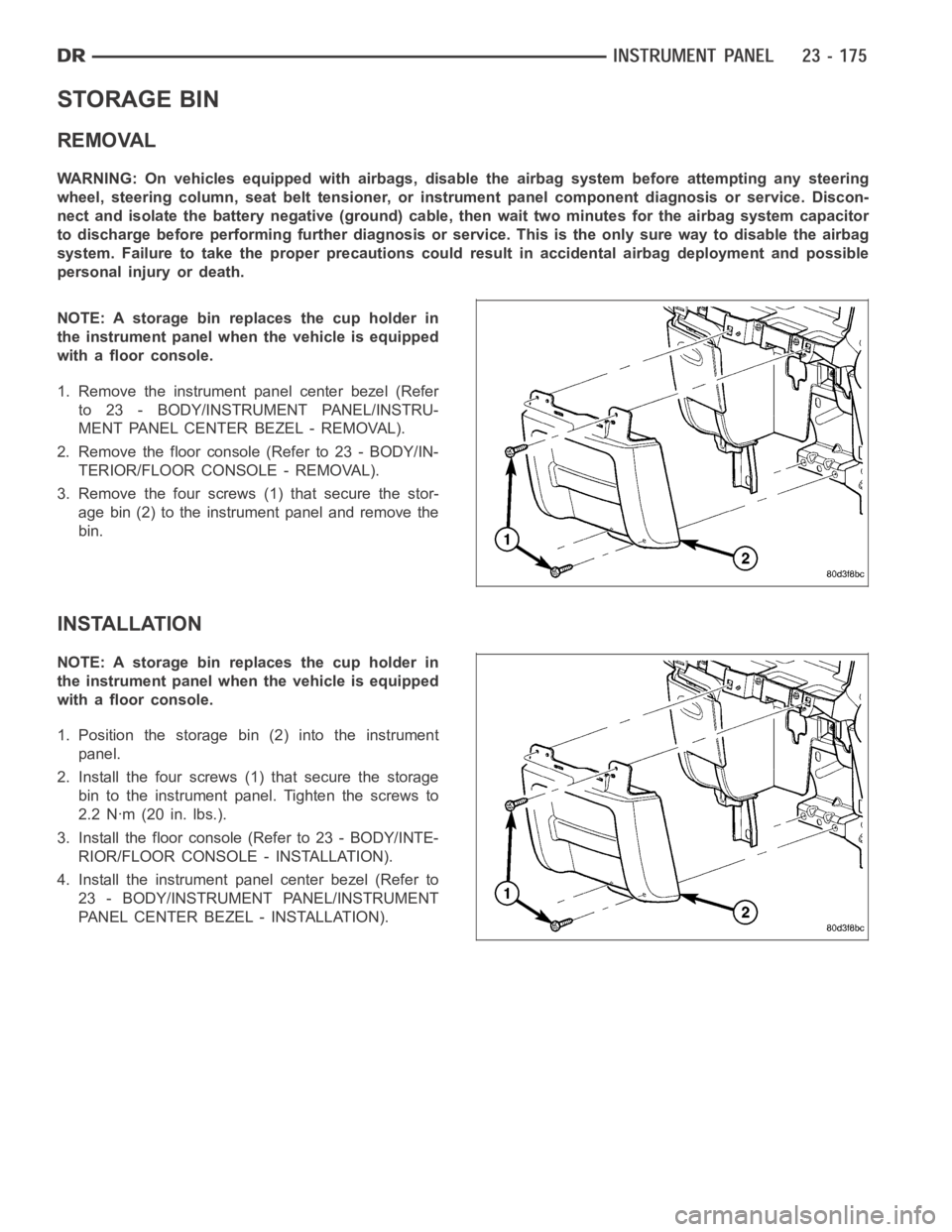
3. Remove the four screws (1) that secure the stor-
age bin (2) to the instrument panel and remove the
bin.
INSTALLATION
NOTE: A storage bin replaces the cup holder in
the instrument panel when the vehicle is equipped
with a floor console.
1. Position the storage bin (2) into the instrument
panel.
2. Install the four screws (1) that secure the storage
bin to the instrument panel. Tighten the screws to
2.2 Nꞏm (20 in. lbs.).
3. Install the floor console (Refer to 23 - BODY/INTE-
RIOR/FLOOR CONSOLE - INSTALLATION).
4. Install the instrument panel center bezel (Refer to
23 - BODY/INSTRUMENT PANEL/INSTRUMENT
PANEL CENTER BEZEL - INSTALLATION).
Page 4559 of 5267
SEATS
WARNING
WARNINGS - RESTRAINT SYSTEM
WARNING: To avoid personal injury or death, during and following any seat beltorchildrestraintanchor
service, carefully inspect all seat belts, buckles, mounting hardware, retractors, tether straps, and anchors
for proper installation, operation, or damage. Replace any belt that is cut, frayed, or torn. Straighten any
belt that is twisted. Tighten any loose fasteners. Replace any belt that has a damaged or ineffective buckle
or retractor. Replace any belt that has a bent or damaged latch plate or anchor plate. Replace any child
restraint anchor or the unit to which the anchor is integral that has been bent or damaged. Never attempt to
repair a seat belt or child restraint component. Always replace damaged orineffective seat belt and child
restraint components with the correct, new and unused replacement parts listed in the DaimlerChrysler
Mopar
Parts Catalog.
WARNING: To avoid personal injury or death, on vehicles equipped with airbags, disable the supplemental
restraint system before attempting any steering wheel, steering column,airbag, seat belt tensioner, impact
sensor, or instrument panel component diagnosis or service. Disconnect and isolate the battery negative
(ground) cable, then wait two minutes for the system capacitor to discharge before performing further diag-
nosis or service. This is the only sure way to disable the supplemental restraint system. Failure to take the
proper precautions could result in accidental airbag deployment.
WARNING: To avoid personal injury or death on vehicles equipped with airbags, before performing any
welding operations disconnect and isolate the battery negative (ground)cable and disconnect all wire har-
ness connectors from the Occupant Restraint Controller (ORC). Failure totake the proper precautions could
result in accidental airbag deployment and other possible damage to the supplemental restraint system cir-
cuits and components.
WARNING: To avoid personal injury or death, do not attempt to dismantle an airbag unit or tamper with its
inflator. Do not puncture, incinerate, or bring into contact with electricity. Do not store at temperatures
exceeding 93° C (200° F). An airbag inflator unit may contain sodium azide and potassium nitrate. These
materials are poisonous and extremely flammable. Contact with acid, water, or heavy metals may produce
harmful and irritating gases (sodium hydroxide is formed in the presence of moisture) or combustible com-
pounds. An airbag inflator unit may also contain a gas canister pressurizedtoover2500psi.
WARNING: To avoid personal injury or death, when handling a seat belt tensioner retractor, proper care
should be exercised to keep fingers out from under the retractor cover and away from the seat belt webbing
where it exits from the retractor cover.
WARNING: To avoid personal injury or death, replace all restraint system components only with parts spec-
ified in the DaimlerChrysler Mopar
Parts Catalog. Substitute parts may appear interchangeable, but internal
differences may result in inferior occupant protection.
WARNING: To avoid personal injury or death, the fasteners, screws, and bolts originally used for the
restraint system components must never be replaced with any substitutes.These fasteners have special
coatings and are specifically designed for the restraint system. Any timea new fastener is needed, replace
it with the correct fasteners provided in the service package or specifiedin the DaimlerChrysler Mopar
Parts Catalog.
WARNING: To avoid personal injury or death, when a steering column has an airbag unit attached, never
place the column on the floor or any other surface with the steering wheel orairbag unit face down.
Page 4605 of 5267
BACKLITE VENT GLASS - REGULATOR
REMOVAL
1. Disconnect and isolate the battery negative cable.
2. Remove the rear seats (Refer to 23 - BODY/SEATS/SEAT - REMOVAL).
3. Remove the rear cab back panel (Refer to 23 - BODY/INTERIOR/REAR CAB BACKPANEL TRIM - REMOVAL).
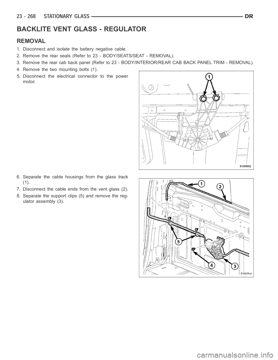
4. Remove the two mounting bolts (1).
5. Disconnect the electrical connector to the power
motor.
6. Separate the cable housings from the glass track
(1).
7. Disconnect the cable ends from the vent glass (2).
8. Separate the support clips (5) and remove the reg-
ulator assembly (3).
Page 4606 of 5267
INSTALLATION
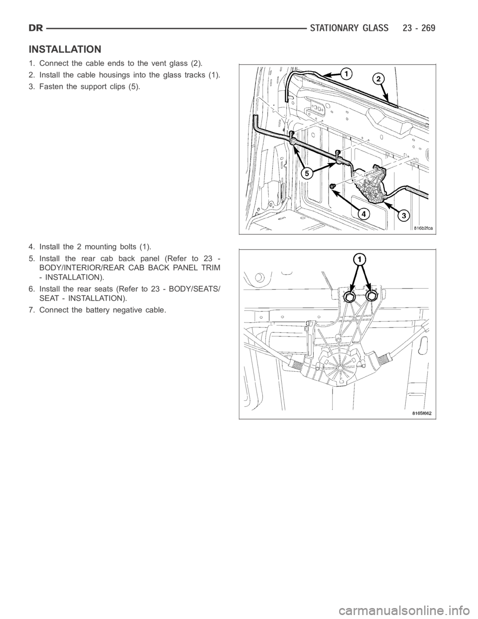
1. Connect the cable ends to the vent glass (2).
2. Install the cable housings into the glass tracks (1).
3. Fasten the support clips (5).
4. Install the 2 mounting bolts (1).
5. Install the rear cab back panel (Refer to 23 -
BODY/INTERIOR/REAR CAB BACK PANEL TRIM
- INSTALLATION).
6. Install the rear seats (Refer to 23 - BODY/SEATS/
SEAT - INSTALLATION).
7. Connect the battery negative cable.
Page 4609 of 5267
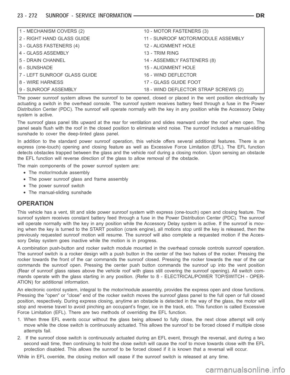
1 - MECHANISM COVERS (2) 10 - MOTOR FASTENERS (3)
2 - RIGHT HAND GLASS GUIDE 11 - SUNROOF MOTOR/MODULE ASSEMBLY
3 - GLASS FASTENERS (4) 12 - ALIGNMENT HOLE
4 - GLASS ASSEMBLY 13 - TRIM RING
5 - DRAIN CHANNEL 14 - ASSEMBLY FASTENERS (8)
6 - SUNSHADE 15 - ALIGNMENT HOLE
7 - LEFT SUNROOF GLASS GUIDE 16 - WIND DEFLECTOR
8 - WIRE HARNESS 17 - GLASS GUIDE FOOT
9 - SUNROOF ASSEMBLY 18 - WIND DEFLECTOR STRAP SCREWS (2)
The power sunroof system allows the sunroof to be opened, closed or placed in the vent position electrically by
actuating a switch in the overhead console. The sunroof system receives battery feed through a fuse in the Power
Distribution Center (PDC). The sunroof will operate normally with the keyin any position while the Accessory Delay
system is active.
The sunroof glass panel tilts upward at the rear for ventilation and slidesrearward under the roof when open. The
panel seals flush with the roof in the closed position to eliminate wind noise. The sunroof includes a manual-sliding
sunshade to cover the deep-tinted glass panel.
In addition to the standard power sunroof operation, this vehicle offers several additional features. There is an
express (one-touch) opening and closing feature as well as Excessive Force Limitation (EFL). The EFL function
detects obstacles trapped between the glass and the vehicle roof during a closing motion. Upon sensing an obstacle
the EFL function will reverse direction of the glass to allow removal of theobstacle.
The main components of thepower sunroof system are:
The motor/module assembly
The power sunroof glass and frame assembly
The power sunroof switch
The manual-sliding sunshade
OPERATION
This vehicle has a vent, tilt and slide power sunroof system with express (one-touch) open and closing feature. The
sunroof system receives constant battery feed through a fuse in the Power Distribution Center (PDC). The sunroof
will operate normally with the key in any position while the Accessory Delay system is active. If the sunroof is mov-
ing when the key is turned to the START position (crank engine), all motionsstop until the key is released, then the
previously requested sunroof motion will resume. The sunroof will also complete a requested motion if the Acces-
sory Delay system goes inactivewhile the motion is in progress.
A combination push-button and rocker switch module mounted in the overhead console controls sunroof operation.
The sunroof switch is a rocker design with a push button in the center of the two halves of the rocker. Pressing the
rocker towards the front of the car commands the sunroof closed. Pressing the rocker towards the rear of the car
commands the sunroof open. Pressing the center push button commands the sunroof up into the vent position
(Rear of sunroof glass raises above the vehicle roof with glass still covering the sunroof opening). All switch com-
mands operate with the glass startingin any position. (Refer to 8 - ELECTRICAL/POWER TOP/SWITCH - OPER-
ATION) for additional information.
An electronic control system, integralto the motor/module assembly, provides the express open and close functions.
Pressing the
openorcloseend of the rocker switch moves the sunroof glass panel to the full open or fullclosed
position, respectively. During express closing, anytime an obstacle is detected in the way of the glass, the motor will
stop and reverse travel to avoid pinching an occupant’s finger, ice in the track, etc. This function is called Excessive
Force Limitation (EFL). There are two methods of overriding the EFL function.
1. When three EFL events occur without the glass being allowed to fully close, the next close attempt will only
move while the close switch is continuously actuated. This allows the sunrooftobeforcedclosedifmultipleclose
attempts fail.
2. If the sunroof close switch is continuously actuated during an EFL event, through the reversal, and during a two
second wait time, then continuing to hold the close switch will cause the roof to move towards close with the EFL
protection disabled. This allows the sunroof to be forced closed if it is known that a reversal will occur.
While in EFL override, the closing motion will cease if the sunroof switch is released at any time.
Page 4610 of 5267
The motor/module is programmed to learn the speed required to drive the panel based on position and recalibrates
itself as needed. If the sunroof becomes uncalibrated, it will only respond to the vent switch. If the vent switch is
pressed, the glass will move toward vent; if the switch is released, all motion stops. In the event that the sunroof
system becomes uncalibrated performthe sunroof position calibration procedure, (Refer to 8 - ELECTRICAL/
POWER TOP/MOTOR - STANDARD PROCEDURE -SUNROOF POSITION CALIBRATION).
DIAGNOSIS AND TESTING
POWER TOP - SUNROOF
Any diagnosis of the power sunroof system should begin with the use of a scantool and the proper Diagnostic
Procedures Information. The scan tool can provide confirmation that the Controller Area Network (CAN) Data Bus is
functional, that all of the electronic modules are sending and receiving the proper messages on the CAN Data Bus,
and that the power sunroof motor is being sent the proper hard wired output by the sunroof switch.
For complete circuit diagrams, refer to the appropriate wiring information. The wiring information includes wiring dia-
grams, proper wire and connector repair procedures, details of wire harness routing and retention, connector pin-out
information and location views for the various wire harness connectors, splices and grounds.
Refer to the appropriate diagnostic information.
SUNROOF
Refer to SUNROOF DIAGNOSIS CHART for possible causes. Before beginning sunroof diagnostics verify that all
other power accessories are in proper operating condition. If not, a common electrical problem may exist. Refer to
Wiring Diagrams, in this publication for circuit, splice and component descriptions. Check the condition of the circuit
protection (20 amp circuit breaker in the Junction Block). Inspect all wiring connector pins for proper engagement
and continuity. Check for battery voltage at the power sunroof controller, refer to Wiring Diagrams, for circuit infor-
mation. If battery voltage of more than 10 volts is detected at the controller, proceed with the following tests (the
controller will not operate at less than 10 volts).
Before beginning diagnosis for wind noise or water leaks, verify that the problem was not caused by releasing the
control switch before the sunroof was fully closed. The sunroof module hasa water-management system. If how-
ever, the sunroof glass is in a partial closed position, high pressure water may be forced beyond the water man-
agement system boundariesand onto the headlining.
Every time the sunroof module loses power it must be initialized. This is done by connecting power to the sunroof
and moving the sunroof toward the closed position. When initialization occurs a slight “kick” in the sunroof module
will be seen and heard. This is the indication that the sunroof module is initialized
SUNROOF DIAGNOSIS CHART
SYMPTOM POSSIBLE CAUSE
Sunroof motor inoperative. Faulty control switch.
Faulty circuit ground between sunroof module, control switch,
and body harness.
Faulty power circuit between sunroof module, control switch,
and body harness.
Faulty sunroof drive motor.
Faulty sunroof module.
Audible whine when switch is depressed,
sunroof does not operate.Faulty sunroof drive motor.
Binding cable.
Audible clicking or ratcheting when switch is
pressed, sunroof does not operate.Broken or worn drive cable.
Worn drive motor gear.
Mechanisms not synchronized.
Page 4613 of 5267
ASSEMBLY-MODULE
REMOVAL
WARNING: The Excessive Force Limitation (EFL)
feature must be calibrated any time a sunroof
motor/module is replaced with a new component.
Failure to perform this procedure could result in
vehicle damage and/or personal injury. (Refer to 8
- ELECTRICAL/POWER TOP/MOTOR - STANDARD
PROCEDURE - EXCESSIVE FORCE LIMITATION
(EFL) CALIBRATION) for the appropriate proce-
dure.
1. Move glass panel to the fully closed position.
2. Disconnect and isolate the battery negative cable.
3. Remove headliner (Refer to 23 - BODY/INTERIOR/
HEADLINER - REMOVAL).
4. Disconnect the sunroof wire harness electrical
connector.
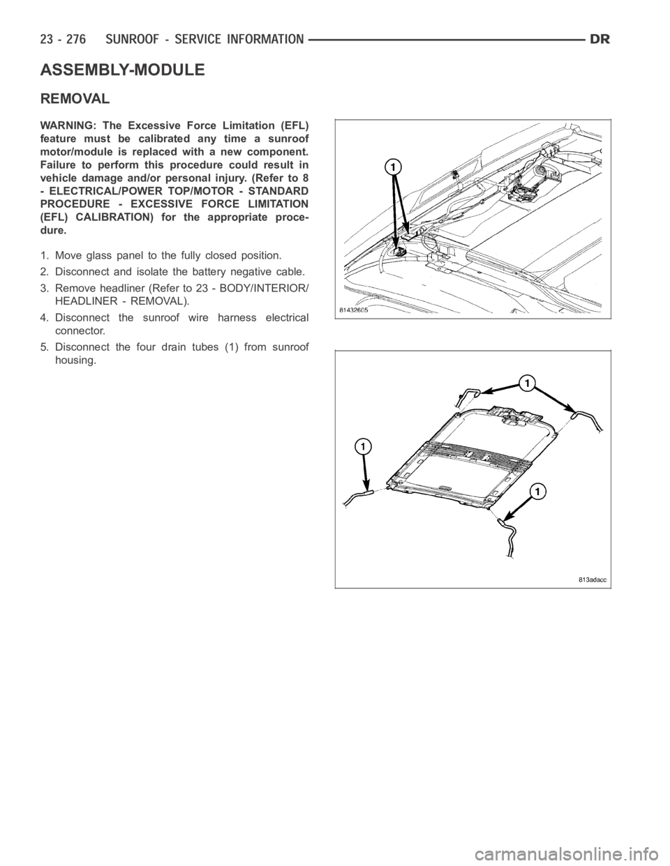
5. Disconnect the four drain tubes (1) from sunroof
housing.