2006 DODGE RAM SRT-10 battery
[x] Cancel search: batteryPage 3772 of 5267
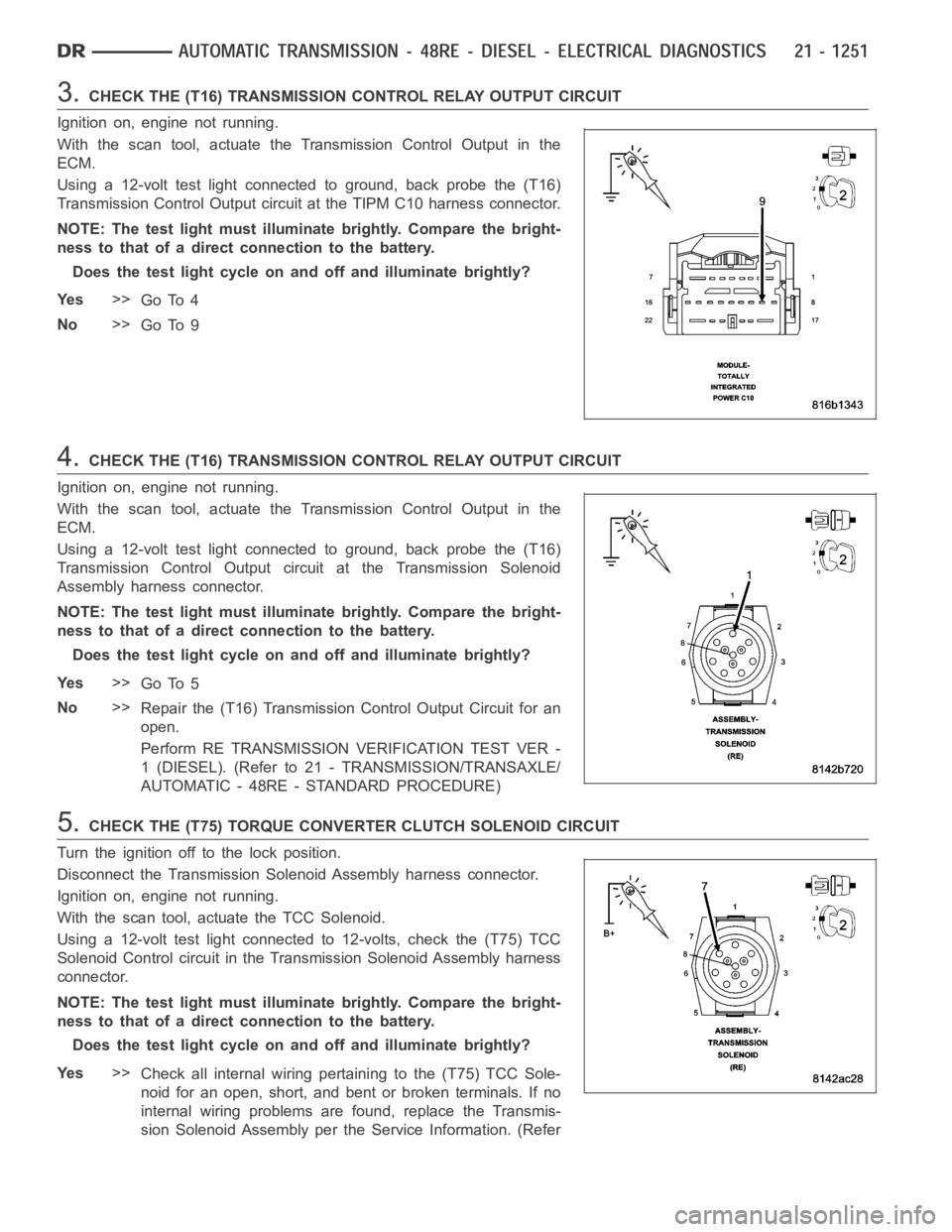
3.CHECK THE (T16) TRANSMISSION CONTROL RELAY OUTPUT CIRCUIT
Ignition on, engine not running.
With the scan tool, actuate the Transmission Control Output in the
ECM.
Using a 12-volt test light connected to ground, back probe the (T16)
Transmission Control Output circuit at the TIPM C10 harness connector.
NOTE: The test light must illuminate brightly. Compare the bright-
ness to that of a direct connection to the battery.
Does the test light cycle on and off and illuminate brightly?
Ye s>>
Go To 4
No>>
Go To 9
4.CHECK THE (T16) TRANSMISSION CONTROL RELAY OUTPUT CIRCUIT
Ignition on, engine not running.
With the scan tool, actuate the Transmission Control Output in the
ECM.
Using a 12-volt test light connected to ground, back probe the (T16)
Transmission Control Output circuit at the Transmission Solenoid
Assembly harness connector.
NOTE: The test light must illuminate brightly. Compare the bright-
ness to that of a direct connection to the battery.
Does the test light cycle on and off and illuminate brightly?
Ye s>>
Go To 5
No>>
Repair the (T16) Transmission Control Output Circuit for an
open.
Perform RE TRANSMISSION VERIFICATION TEST VER -
1 (DIESEL). (Refer to 21 - TRANSMISSION/TRANSAXLE/
AUTOMATIC - 48RE - STANDARD PROCEDURE)
5.CHECK THE (T75) TORQUE CONVERTER CLUTCH SOLENOID CIRCUIT
Turn the ignition off to the lock position.
Disconnect the Transmission Solenoid Assembly harness connector.
Ignition on, engine not running.
With the scan tool, actuate the TCC Solenoid.
Using a 12-volt test light connected to 12-volts, check the (T75) TCC
Solenoid Control circuit in the Transmission Solenoid Assembly harness
connector.
NOTE: The test light must illuminate brightly. Compare the bright-
ness to that of a direct connection to the battery.
Does the test light cycle on and off and illuminate brightly?
Ye s>>
Check all internal wiring pertaining to the (T75) TCC Sole-
noid for an open, short, and bent or broken terminals. If no
internal wiring problems are found, replace the Transmis-
sion Solenoid Assembly per the Service Information. (Refer
Page 3779 of 5267
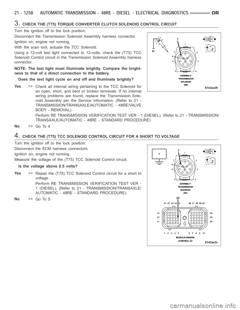
3.CHECK THE (T75) TORQUE CONVERTER CLUTCH SOLENOID CONTROL CIRCUIT
Turn the ignition off to the lock position.
Disconnect the Transmission Solenoid Assembly harness connector.
Ignition on, engine not running.
With the scan tool, actuate the TCC Solenoid.
Using a 12-volt test light connected to 12-volts, check the (T75) TCC
Solenoid Control circuit in the Transmission Solenoid Assembly harness
connector.
NOTE: The test light must illuminate brightly. Compare the bright-
ness to that of a direct connection to the battery.
Does the test light cycle on and off and illuminate brightly?
Ye s>>
Check all internal wiring pertaining to the TCC Solenoid for
an open, short, and bent or broken terminals. If no internal
wiring problems are found, replace the Transmission Sole-
noid Assembly per the Service Information. (Refer to 21 -
TRANSMISSION/TRANSAXLE/AUTOMATIC - 48RE/VALVE
BODY - REMOVAL)
Perform RE TRANSMISSION VERIFICATION TEST VER - 1 (DIESEL). (Refer to 21 - TRANSMISSION/
TRANSAXLE/AUTOMATIC - 48RE - STANDARD PROCEDURE)
No>>
Go To 4
4.CHECK THE (T75) TCC SOLENOID CONTROL CIRCUIT FOR A SHORT TO VOLTAGE
Turn the ignition off to the lock position.
Disconnect the ECM harness connectors.
Ignition on, engine not running.
Measure the voltage of the (T75) TCC Solenoid Control circuit.
Is the voltage above 0.5 volts?
Ye s>>
Repair the (T75) TCC Solenoid Control circuit for a short to
voltage.
Perform RE TRANSMISSION VERIFICATION TEST VER -
1 (DIESEL). (Refer to 21 - TRANSMISSION/TRANSAXLE/
AUTOMATIC - 48RE - STANDARD PROCEDURE)
No>>
Go To 5
Page 3786 of 5267
PRE-DIAGNOSTIC CHECKOUT (DIESEL)
For a complete wiring diagramRefer to Section 8W
1.PRE-DIAGNOSTIC CHECKOUT
NOTE: Always perform diagnostics with a fully charged battery to avoid false symptoms.
NOTE: Low fluid level can be the cause of many transmission problems. If thefluid level is low locate and
repair the leak then check and adjust the fluid level per the Service Information.
With the scan tool, read engine DTC’s. Check and repair all engine DTCs prior to performing transmission symptom
diagnostics.
Using the wiring diagram/schematic as a guide, inspect the wiring and connectors. Repair as necessary.
Verify the flash level of the Engine Control Module. Some problems are corrected by software upgrades.
Check for any Service Information Tune-ups or Technical Service Bulletins that may apply.
Did any of the above checks or procedures correct the symptom?
Ye s>>
Repair is complete.
Perform RE TRANSMISSION VERIFICATION TEST VER - 1 (DIESEL). (Refer to 21 - TRANSMISSION/
TRANSAXLE/AUTOMATIC - 48RE - STANDARD PROCEDURE)
No>>
Refer to the Transmission category and perform the appropriate symptom(s).
Page 3815 of 5267
REMOVAL
NOTE: The overdrive unit can be removed and serviced separately. It is not necessary to remove the entire
transmission assembly to perform overdrive unit repairs.
1. Disconnect battery negative cable.
2. Raise vehicle.
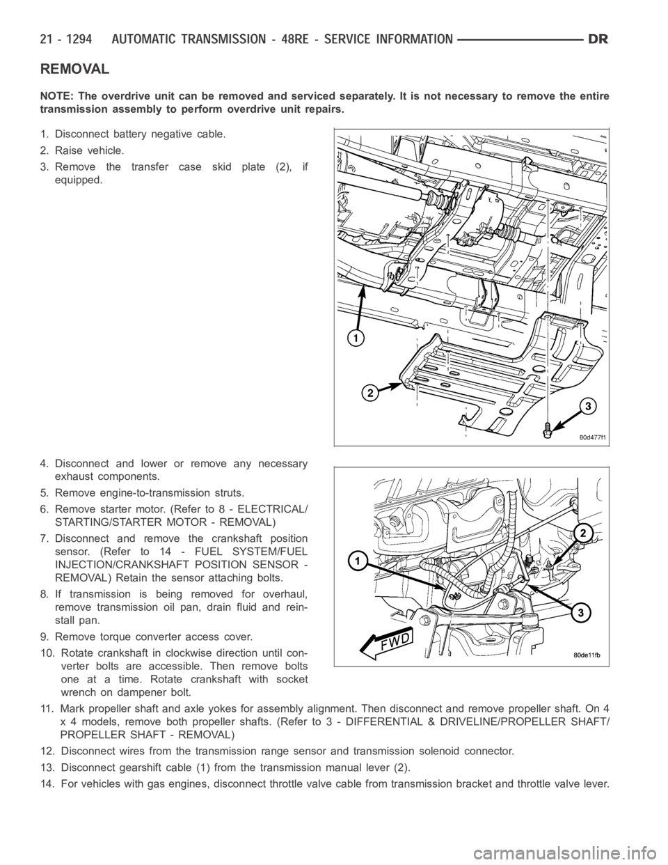
3. Remove the transfer case skid plate (2), if
equipped.
4. Disconnect and lower or remove any necessary
exhaust components.
5. Remove engine-to-transmission struts.
6. Remove starter motor. (Refer to 8 - ELECTRICAL/
STARTING/STARTER MOTOR - REMOVAL)
7. Disconnect and remove the crankshaft position
sensor. (Refer to 14 - FUEL SYSTEM/FUEL
INJECTION/CRANKSHAFT POSITION SENSOR -
REMOVAL) Retain the sensor attaching bolts.
8. If transmission is being removed for overhaul,
remove transmission oil pan, drain fluid and rein-
stall pan.
9. Remove torque converter access cover.
10. Rotate crankshaft in clockwise direction until con-
verter bolts are accessible. Then remove bolts
one at a time. Rotate crankshaft with socket
wrench on dampener bolt.
11. Mark propeller shaft and axle yokes for assembly alignment. Then disconnect and remove propeller shaft. On 4
x 4 models, remove both propeller shafts. (Refer to 3 - DIFFERENTIAL & DRIVELINE/PROPELLER SHAFT/
PROPELLER SHAFT - REMOVAL)
12. Disconnect wires from the transmission range sensor and transmissionsolenoid connector.
13. Disconnect gearshift cable (1) from the transmission manual lever (2).
14. For vehicles with gas engines, disconnect throttle valve cable from transmission bracket andthrottle valve lever.
Page 3943 of 5267
MECHANISM-SHIFT
DESCRIPTION
The gear shift mechanism provides six shift positions which are:
PA R K ( P )
REVERSE (R)
NEUTRAL (N)
DRIVE (D)
Manual SECOND (2)
Manual LOW (1)
OPERATION
Manual LOW (1) range provides first gear only. Overrun braking is also provided in this range. Manual SECOND (2)
range provides first and second gear only.
DRIVE range provides first, second, third, and overdrive fourth gear ranges. The shift into overdrive fourth gear
range occurs only after the transmission has completed the shift into D third gear range. No further movement of the
shift mechanism is required to complete the 3-4 shift.
The fourth gear upshift occurs automatically when the overdrive selectorswitch is in the ON position. No upshift to
fourth gear will occur if any of the following are true:
The transmission fluid temperature is below 10° C (50° F) or above 121° C (250° F).
The shift to third is not yet complete.
Vehicle speed is too low for the 3-4 shift to occur.
Battery temperature is below -5° C (23° F).
Page 4033 of 5267
When Monitored:
Ignition on. Battery voltage between 9.0 and 16.0 volts.
Set Condition:
The TIPM detects a short to ground on the Transfer Case Position Sensor Signal circuit for 2.0 seconds.
Possible Causes
(T103) 5 VOLT SUPPLY CIRCUIT OPEN
(T103) 5 VOLT SUPPLY CIRCUIT SHORTED TO GROUND
(D201) MODE SENSOR A CIRCUIT SHORTED TO GROUND
(D201) MODE SENSOR A CIRCUIT SHORTED TO (G180) SENSOR RETURN CIRCUIT
SHIFT MOTOR/MODE SENSOR ASSEMBLY
TOTALLY INTERGRATED POWER MODULE (TIPM)
Diagnostic Test
1.T-CASE POSITION SENSOR VOLTAGE BELOW 0.2 VOLTS
Ignition on, engine not running.
With the scan tool under TIPM, read the T-Case Position Sensor voltage.
Is the voltage below 0.2 volts?
Ye s>>
Go to 2
No>>
Go to 8
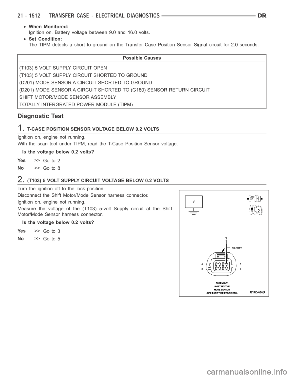
2.(T103) 5 VOLT SUPPLY CIRCUIT VOLTAGE BELOW 0.2 VOLTS
Turn the ignition off to the lock position.
Disconnect the Shift Motor/Mode Sensor harness connector.
Ignition on, engine not running.
Measure the voltage of the (T103) 5-volt Supply circuit at the Shift
Motor/Mode Sensor harness connector.
Is the voltage below 0.2 volts?
Ye s>>
Go to 3
No>>
Go to 5
Page 4037 of 5267
When Monitored:
With the ignition on. Battery voltage between 9.0 and 16.0 volts
Set Condition:
The TIPM detects 5.0 volts on the Transfer Case Range Position Sensor Signal circuit for 2.0 seconds when
voltage should not be present.
Possible Causes
(T103) 5 VOLT SUPPLY CIRCUIT SHORTED TO VOLTAGE
(D201) MODE SENSOR A CIRCUIT SHORTED TO VOLTAGE
(D201) MODE SENSOR A CIRCUIT OPEN
(G180) TIPM SENSOR RETURN CIRCUIT OPEN
SHIFT MOTOR/MODE SENSOR ASSEMBLY
TOTALLY INTEGRATED POWER MODULE (TIPM)
Diagnostic Test
1.T-CASE POSITION SENSOR VOLTAGE ABOVE 4.8 VOLTS
Ignition on, engine not running.
With the scan tool under TIPM, read the T-Case Position sensor voltage.
Is the voltage above 4.8 volts?
Ye s>>
Go To 2
No>>
Go to 7
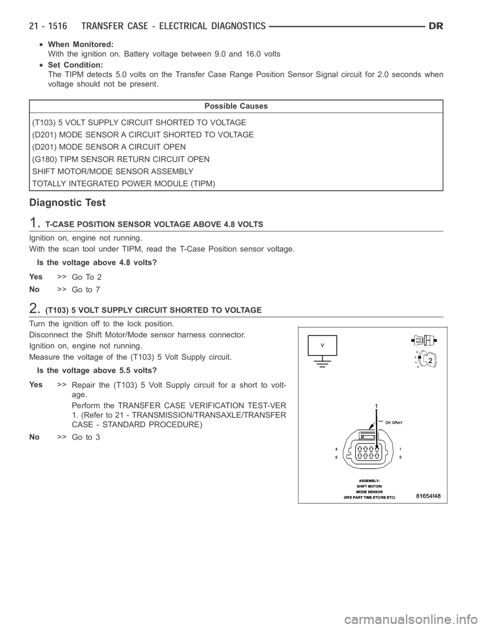
2.(T103) 5 VOLT SUPPLY CIRCUIT SHORTED TO VOLTAGE
Turn the ignition off to the lock position.
Disconnect the Shift Motor/Mode sensor harness connector.
Ignition on, engine not running.
Measure the voltage of the (T103) 5 Volt Supply circuit.
Is the voltage above 5.5 volts?
Ye s>>
Repair the (T103) 5 Volt Supply circuit for a short to volt-
age.
Perform the TRANSFER CASE VERIFICATION TEST-VER
1. (Refer to 21 - TRANSMISSION/TRANSAXLE/TRANSFER
CASE - STANDARD PROCEDURE)
No>>
Go to 3
Page 4043 of 5267
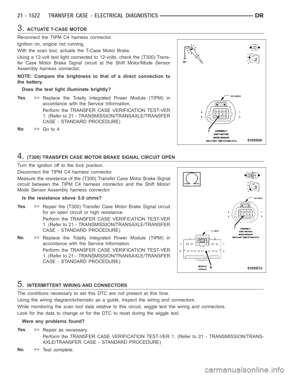
3.ACTUATE T-CASE MOTOR
Reconnect the TIPM C4 harness connector.
Ignition on, engine not running.
With the scan tool, actuate the T-Case Motor Brake.
Using a 12-volt test light connected to 12-volts, check the (T300) Trans-
fer Case Motor Brake Signal circuit at the Shift Motor/Mode Sensor
Assembly harness connector.
NOTE: Compare the brightness to that of a direct connection to
the battery.
Does the test light illuminate brightly?
Ye s>>
Replace the Totally Integrated Power Module (TIPM) in
accordance with the Service Information.
Perform the TRANSFER CASE VERIFICATION TEST-VER
1. (Refer to 21 - TRANSMISSION/TRANSAXLE/TRANSFER
CASE - STANDARD PROCEDURE)
No>>
Go to 4
4.(T300) TRANSFER CASE MOTOR BRAKE SIGNAL CIRCUIT OPEN
Turn the ignition off to the lock position.
Disconnect the TIPM C4 harness connector.
Measure the resistance of the (T300) Transfer Case Motor Brake Signal
circuit between the TIPM C4 harness connector and the Shift Motor/
Mode Sensor Assembly harness connector.
Is the resistance above 5.0 ohms?
Ye s>>
Repair the (T300) Transfer Case Motor Brake Signal circuit
for an open circuit or high resistance.
Perform the TRANSFER CASE VERIFICATION TEST-VER
1. (Refer to 21 - TRANSMISSION/TRANSAXLE/TRANSFER
CASE - STANDARD PROCEDURE)
No>>
Replace the Totally Integrated Power Module (TIPM) in
accordance with the Service Information.
Perform the TRANSFER CASE VERIFICATION TEST-VER
1. (Refer to 21 - TRANSMISSION/TRANSAXLE/TRANSFER
CASE - STANDARD PROCEDURE)
5.INTERMITTENT WIRING AND CONNECTORS
The conditions necessary to set this DTC are not present at this time.
Using the wiring diagram/schematic as a guide, inspect the wiring and connectors.
While monitoring the scan tool data relative to this circuit, wiggle test the wiring and connectors.
Look for the data to change or for the DTC to reset during the wiggle test.
Were any problems found?
Ye s>>
Repair as necessary.
Perform the TRANSFER CASE VERIFICATION TEST-VER 1. (Refer to 21 - TRANSMISSION/TRANS-
AXLE/TRANSFER CASE - STANDARD PROCEDURE)
No>>
Te s t c o m p l e t e .