Page 4366 of 5267
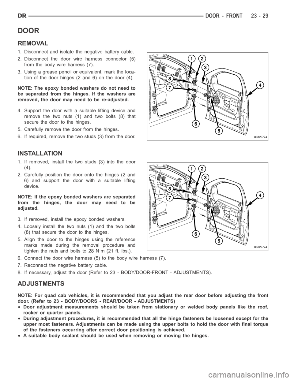
DOOR
REMOVAL
1. Disconnect and isolate the negative battery cable.
2. Disconnect the door wire harness connector (5)
from the body wire harness (7).
3. Using a grease pencil or equivalent, mark the loca-
tion of the door hinges (2 and 6) on the door (4).
NOTE: The epoxy bonded washers do not need to
be separated from the hinges. If the washers are
removed,thedoormayneedtobere-adjusted.
4. Support the door with a suitable lifting device and
remove the two nuts (1) and two bolts (8) that
secure the door to the hinges.
5. Carefully remove the door from the hinges.
6. If required, remove the two studs (3) from the door.
INSTALLATION
1. If removed, install the two studs (3) into the door
(4).
2. Carefully position the door onto the hinges (2 and
6) and support the door with a suitable lifting
device.
NOTE: If the epoxy bonded washers are separated
from the hinges, the door may need to be
adjusted.
3. If removed, install the epoxy bonded washers.
4. Loosely install the two nuts (1) and the two bolts
(8) that secure the door to the hinges.
5. Align the door to the hinges using the reference
marks made during the removal procedure and
tighten the nuts and bolts to 28 Nꞏm (21 ft. lbs.).
6. Connect the door wire harness (5) to the body wire harness (7).
7. Reconnect the negative battery cable.
8. If necessary, adjust the door (Refer to 23 - BODY/DOOR-FRONT - ADJUSTMENTS).
ADJUSTMENTS
NOTE: For quad cab vehicles, it is recommended that you adjust the rear doorbefore adjusting the front
door. (Refer to 23 - BODY/DOORS - REAR/DOOR - ADJUSTMENTS)
Door adjustment measurements should be taken from stationary or welded body panels like the roof,
rocker or quarter panels.
During adjustment procedures, it is recommended that all the hinge fasteners be loosened except for the
upper most fasteners. Adjustments can be made using the upper bolts to holdthe door with final torque
of the fasteners occurring after correct door positioning is achieved.
A suitable body sealant should be used when removing or moving the hinges.
Page 4373 of 5267
EXTERIOR HANDLE
REMOVAL
1. Disconnect and isolate the negative battery cable.
2. Remove the door glass (Refer to 23 - BODY/
DOOR - FRONT/DOOR GLASS - REMOVAL).
3. If equipped, disconnect the exterior handle wire
lead (7) from the door wire harness connector (3).
4. Disconnect the actuator rods (6 and 8) for the door
latch (5) from the exterior handle (1).
5. Remove the two nuts (2) that secure the exterior
handle to the door (4) and remove the handle.
INSTALLATION
1. Position the exterior handle (1) into the door (4).
2. Install the two nuts (2) that secure the exterior han-
dle to the door. Tighten the nuts to 10 Nꞏm (89 in.
lbs.).
3. Connect the actuator rods (6 and 8) for the door
latch (5) to the exterior handle.
4. If equipped, connect the exterior handle wire lead
(7) to the door wire harness connector (3).
5. Install the door glass (Refer to 23 - BODY/DOOR -
FRONT/DOOR GLASS - INSTALLATION).
6. Reconnect the negative battery cable.
Page 4394 of 5267
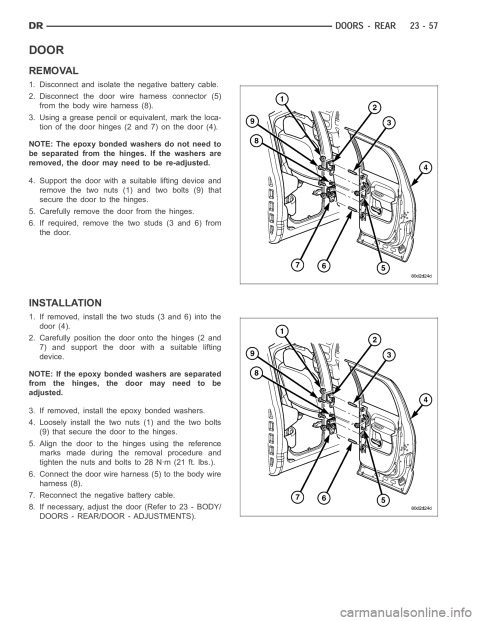
DOOR
REMOVAL
1. Disconnect and isolate the negative battery cable.
2. Disconnect the door wire harness connector (5)
from the body wire harness (8).
3. Using a grease pencil or equivalent, mark the loca-
tion of the door hinges (2 and 7) on the door (4).
NOTE: The epoxy bonded washers do not need to
be separated from the hinges. If the washers are
removed,thedoormayneedtobere-adjusted.
4. Support the door with a suitable lifting device and
remove the two nuts (1) and two bolts (9) that
secure the door to the hinges.
5. Carefully remove the door from the hinges.
6. If required, remove the two studs (3 and 6) from
the door.
INSTALLATION
1. If removed, install the two studs (3 and 6) into the
door (4).
2. Carefully position the door onto the hinges (2 and
7) and support the door with a suitable lifting
device.
NOTE: If the epoxy bonded washers are separated
from the hinges, the door may need to be
adjusted.
3. If removed, install the epoxy bonded washers.
4. Loosely install the two nuts (1) and the two bolts
(9) that secure the door to the hinges.
5. Align the door to the hinges using the reference
marks made during the removal procedure and
tighten the nuts and bolts to 28 Nꞏm (21 ft. lbs.).
6. Connect the door wire harness (5) to the body wire
harness (8).
7. Reconnect the negative battery cable.
8. If necessary, adjust the door (Refer to 23 - BODY/
DOORS - REAR/DOOR - ADJUSTMENTS).
Page 4432 of 5267
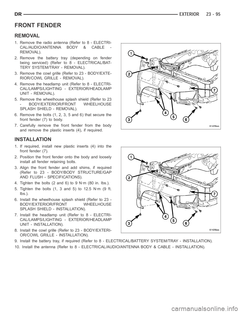
FRONT FENDER
REMOVAL
1. Remove the radio antenna (Refer to 8 - ELECTRI-
CAL/AUDIO/ANTENNA BODY & CABLE -
REMOVAL).
2. Remove the battery tray (depending on fender
beingserviced)(Referto8-ELECTRICAL/BAT-
TERY SYSTEM/TRAY - REMOVAL).
3. Remove the cowl grille (Refer to 23 - BODY/EXTE-
RIOR/COWL GRILLE - REMOVAL).
4. Remove the headlamp unit (Refer to 8 - ELECTRI-
CAL/LAMPS/LIGHTING - EXTERIOR/HEADLAMP
UNIT - REMOVAL).
5. Remove the wheelhouse splash shield (Refer to 23
- BODY/EXTERIOR/FRONT WHEELHOUSE
SPLASH SHIELD - REMOVAL).
6. Remove the bolts (1, 2, 3, 5 and 6) that secure the
front fender (7) to body.
7. Carefully remove the front fender from the body
and remove the plastic inserts (4), if required.
INSTALLATION
1. If required, install new plastic inserts (4) into the
front fender (7).
2. Position the front fender onto the body and loosely
install all fender retaining bolts.
3. Align the front fender and add shims, if required
(Refer to 23 - BODY/BODY STRUCTURE/GAP
AND FLUSH - SPECIFICATIONS).
4. Tighten the bolts (2 and 6) to 9 Nꞏm (80 in. lbs.).
5. Tighten the bolts (1, 3 and 5) to 12.5 Nꞏm (9 ft.
lbs.).
6. Install the wheelhouse splash shield (Refer to 23 -
BODY/EXTERIOR/FRONT WHEELHOUSE
SPLASH SHIELD - INSTALLATION).
7. Install the headlamp unit (Refer to 8 - ELECTRI-
CAL/LAMPS/LIGHTING - EXTERIOR/HEADLAMP
UNIT - INSTALLATION).
8. Install the cowl grille (Refer to 23 - BODY/EXTERI-
OR/COWL GRILLE - INSTALLATION).
9. Install the battery tray, if required (Refer to 8 - ELECTRICAL/BATTERY SYSTEM/TRAY - INSTALLATION).
10. Install the antenna (Refer to 8 - ELECTRICAL/AUDIO/ANTENNA BODY & CABLE - INSTALLATION).
Page 4436 of 5267
REAR FENDER-QUAD CAB MODELS
REMOVAL
1. Disconnect and isolate the negative battery cable.
2. Remove the tail lamp unit (Refer to 8 - ELECTRI-
CAL/LAMPS/LIGHTING - EXTERIOR/TAIL LAMP
UNIT - REMOVAL).
3. Remove the rear wheelhouse splash shield (Refer
to 23 - BODY/EXTERIOR/REAR WHEELHOUSE
SPLASH SHIELD - REMOVAL).
4. Remove the two marker lamp units from the rear
fender (Refer to 8 - ELECTRICAL/LAMPS/LIGHT-
ING - EXTERIOR/MARKER LAMP UNIT -
REMOVAL).
5. Remove the two nuts (2) that secure the rear
fender to the cargo box near the tail lamp opening
(1).
6. Raise and support the vehicle.
7. Remove the two nuts (1) that secure the rear
fender to the rear of the cargo box inner panel (2).
8. Remove the four bolts that secure the bottom
edges of the rear fender to the cargo box.
Page 4439 of 5267
6. Lower the vehicle.
7. Install the two nuts (2) that secure the rear fender
to the cargo box near the tail lamp opening (1).
Tightenthenutsto7Nꞏm(60in.lbs.).
8. Install the two marker lamp units onto the rear
fender (Refer to 8 - ELECTRICAL/LAMPS/LIGHT-
ING - EXTERIOR/MARKER LAMP UNIT - INSTAL-
LATION).
9. Install the rear wheelhouse splash shield (Refer to
23 - BODY/EXTERIOR/REAR WHEELHOUSE
SPLASH SHIELD - INSTALLATION).
10. Install the tail lamp unit (Refer to 8 - ELECTRI-
CAL/LAMPS/LIGHTING - EXTERIOR/TAIL LAMP
UNIT - INSTALLATION).
11. Reconnect the negative battery cable.
Page 4469 of 5267
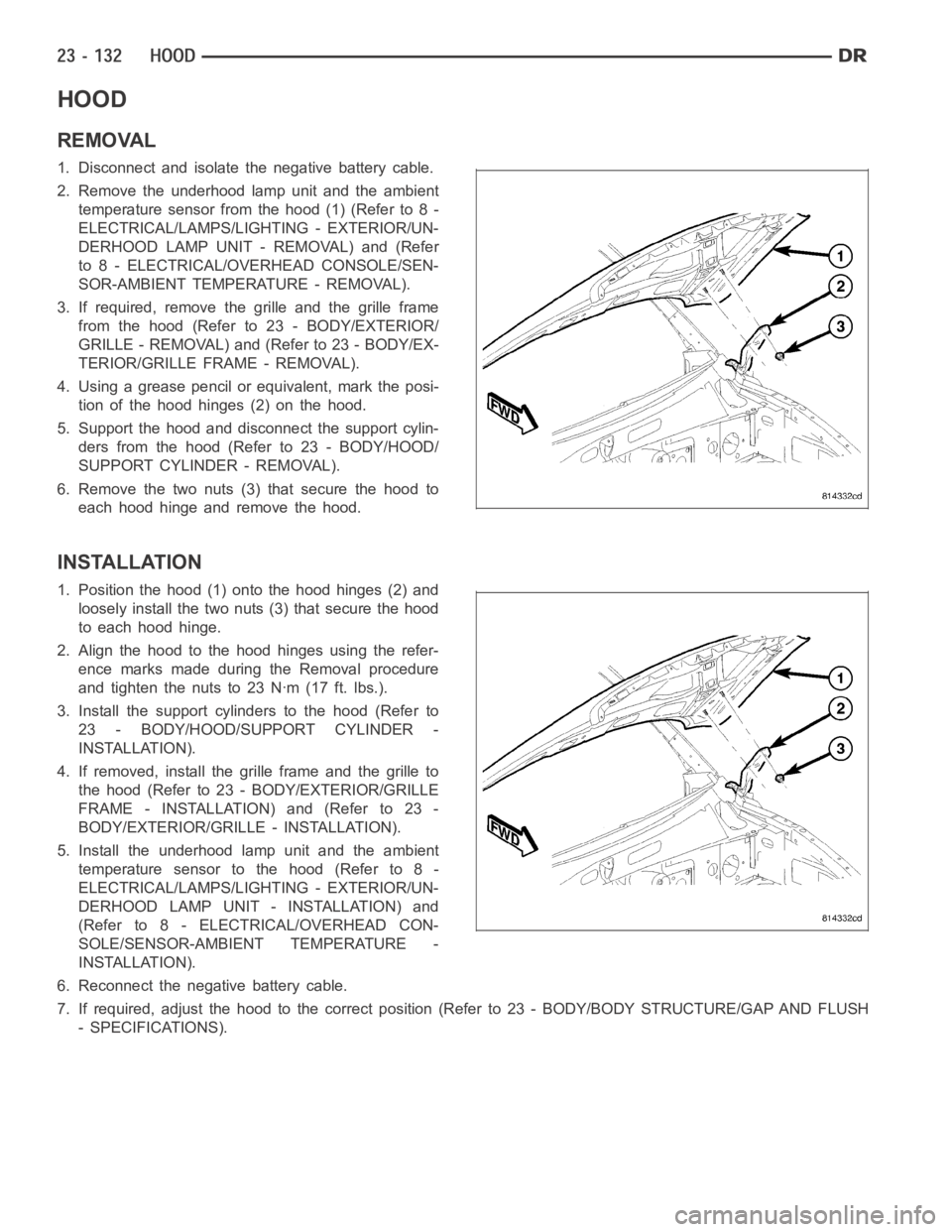
HOOD
REMOVAL
1. Disconnect and isolate the negative battery cable.
2. Remove the underhood lamp unit and the ambient
temperature sensor from the hood (1) (Refer to 8 -
ELECTRICAL/LAMPS/LIGHTING - EXTERIOR/UN-
DERHOOD LAMP UNIT - REMOVAL) and (Refer
to 8 - ELECTRICAL/OVERHEAD CONSOLE/SEN-
SOR-AMBIENT TEMPERATURE - REMOVAL).
3. If required, remove the grille and the grille frame
from the hood (Refer to 23 - BODY/EXTERIOR/
GRILLE - REMOVAL) and (Refer to 23 - BODY/EX-
TERIOR/GRILLE FRAME - REMOVAL).
4. Using a grease pencil or equivalent, mark the posi-
tion of the hood hinges (2) on the hood.
5. Support the hood and disconnect the support cylin-
ders from the hood (Refer to 23 - BODY/HOOD/
SUPPORT CYLINDER - REMOVAL).
6. Remove the two nuts (3) that secure the hood to
each hood hinge and remove the hood.
INSTALLATION
1. Position the hood (1) onto the hood hinges (2) and
loosely install the two nuts (3) that secure the hood
to each hood hinge.
2. Align the hood to the hood hinges using the refer-
ence marks made during the Removal procedure
and tighten the nuts to 23 Nꞏm (17 ft. lbs.).
3. Install the support cylinders to the hood (Refer to
23 - BODY/HOOD/SUPPORT CYLINDER -
INSTALLATION).
4. If removed, install the grille frame and the grille to
the hood (Refer to 23 - BODY/EXTERIOR/GRILLE
FRAME - INSTALLATION) and (Refer to 23 -
BODY/EXTERIOR/GRILLE - INSTALLATION).
5. Install the underhood lamp unit and the ambient
temperature sensor to the hood (Refer to 8 -
ELECTRICAL/LAMPS/LIGHTING - EXTERIOR/UN-
DERHOOD LAMP UNIT - INSTALLATION) and
(Refer to 8 - ELECTRICAL/OVERHEAD CON-
SOLE/SENSOR-AMBIENT TEMPERATURE -
INSTALLATION).
6. Reconnect the negative battery cable.
7. If required, adjust the hood to the correct position (Refer to 23 - BODY/BODY STRUCTURE/GAP AND FLUSH
- SPECIFICATIONS).
Page 4471 of 5267
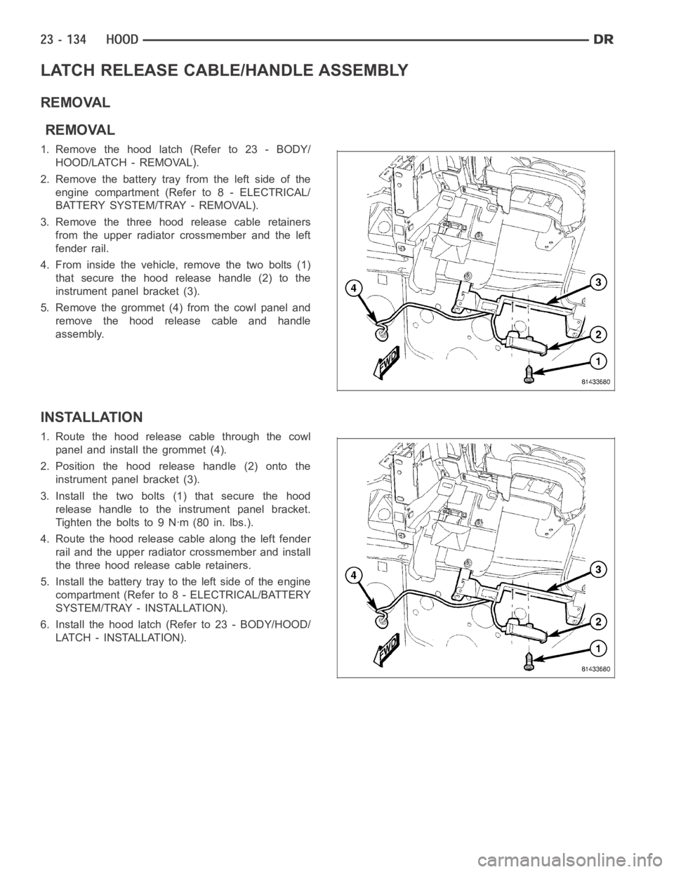
LATCH RELEASE CABLE/HANDLE ASSEMBLY
REMOVAL
REMOVAL
1.Removethehoodlatch(Referto23-BODY/
HOOD/LATCH - REMOVAL).
2. Remove the battery tray from the left side of the
engine compartment (Refer to 8 - ELECTRICAL/
BATTERY SYSTEM/TRAY - REMOVAL).
3. Remove the three hood release cable retainers
from the upper radiator crossmember and the left
fender rail.
4. From inside the vehicle, remove the two bolts (1)
that secure the hood release handle (2) to the
instrument panel bracket (3).
5. Remove the grommet (4) from the cowl panel and
remove the hood release cable and handle
assembly.
INSTALLATION
1. Route the hood release cable through the cowl
panel and install the grommet (4).
2. Position the hood release handle (2) onto the
instrument panel bracket (3).
3. Install the two bolts (1) that secure the hood
release handle to the instrument panel bracket.
Tightentheboltsto9Nꞏm(80in.lbs.).
4. Route the hood release cable along the left fender
rail and the upper radiator crossmember and install
the three hood release cable retainers.
5. Install the battery tray to the left side of the engine
compartment (Refer to 8 - ELECTRICAL/BATTERY
SYSTEM/TRAY - INSTALLATION).
6. Install the hood latch (Refer to 23 - BODY/HOOD/
LATCH - INSTALLATION).