2006 DODGE RAM SRT-10 battery
[x] Cancel search: batteryPage 3362 of 5267
45RFE/545RFE TRANSMISSION VERIFICATION TEST - VER 1
For a complete wiring diagramRefer to Section 8W.
1.
Perform the following after completion of a diagnostic repair:
After completion of the Transmission Verification Test, the Powertrain Verification Test must be per-
formed.
Connect the scan tool to the Data Link Connector (DLC).
Reconnect any disconnected components.
If the PCM has been replaced or updated (flashed), or the transmission has been repaired or replaced, using
the scan tool, perform a Quick Learn Procedure.
With the scan tool, erase all Transmission and Engine DTC’s.
With the scan tool, perform a BATTERY DISCONNECT, this will clear the DTC EVENT DATA
With the scan tool, display Transmission Temperature. Start and run the engine until the Transmission Tem-
perature is HOT.
Check the Transmission fluid level and adjust if necessary. Refer to the Service Information for the Fluid Fill
procedure. (Refer to 21 - TRANSMISSION/TRANSAXLE/AUTOMATIC - 45RFE/545RFE/FLUID - STANDARD
PROCEDURE)
Road test the vehicle.
Perform the following shifts from a standing start with a constant throttle opening of 20 to 25 degrees to the
speeds of 97 Kmh (60 mph); make fifteen to twenty 1 to 2, 2 to 3, 3 to 4 upshifts andfor545RFE,4to5.
Perform the following shifts with speeds below 40 Kmh (25 mph); make five toeight wide open throttle kick-
downs to 1st gear. Allow at least 5 seconds each in 2nd and 3rd gear between each kickdown.
Check for DTCs during and after the road test.
If after performing the road test, if any shift concerns are noted, performthe drive learn procedure for those
affected shifts. (Refer to 8 - ELECTRICAL/ELECTRONIC CONTROL MODULES/TRANSMISSION CONTROL
MODULE - STANDARD PROCEDURE)
Use the EATX OBDII task manager to run Good Trip time in each gear, this will confirm the repair and
to ensure that the DTC does not re-mature.
Were there any Diagnostic Trouble Codes (DTCs) set during the road test?
Ye s>>
Refer to the Transmission category and perform the appropriate symptom. (Refer to 21 - TRANSMIS-
SION/TRANSAXLE/AUTOMATIC - 45RFE/545RFE - DIAGNOSIS AND TESTING)
No>>
Repair is complete.
Page 3372 of 5267
Some suspected converter housing fluid leaks may not be leaks at all. They may only be the result of residual fluid
in the converter housing, or excess fluid spilled during factory fill or fill after repair. Converter housing leaks have
several potential sources. Through careful observation, a leak source can be identified before removing the trans-
mission for repair. Torque converter seal leaks tend to move along the drive hub and onto the rear of the converter.
Pump cover seal leaks tend to run down the cover and the inside surface of thebellhousing.
Some leaks, or suspected leaks, may be particularly difficult to locate. If necessary, a Mopar
approved dye should
be used to locate and confirm a leak.
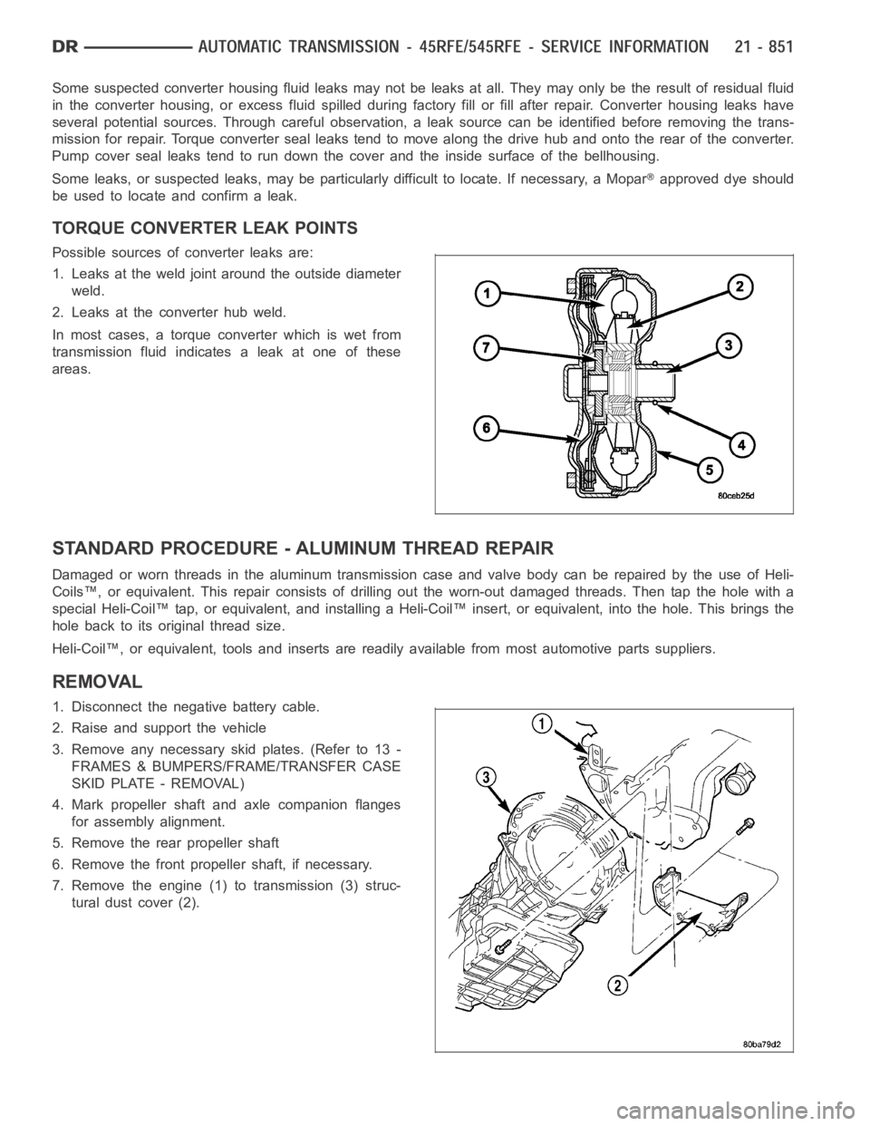
TORQUE CONVERTER LEAK POINTS
Possible sources of converter leaks are:
1. Leaks at the weld joint around the outside diameter
weld.
2. Leaks at the converter hub weld.
In most cases, a torque converter which is wet from
transmission fluid indicates a leak at one of these
areas.
STANDARD PROCEDURE - ALUMINUM THREAD REPAIR
DamagedorwornthreadsinthealuminumtransmissioncaseandvalvebodycanberepairedbytheuseofHeli-
Coils™, or equivalent. This repair consists of drilling out the worn-out damaged threads. Then tap the hole with a
special Heli-Coil™ tap, or equivalent, and installing a Heli-Coil™ insert, or equivalent, into the hole. This brings the
hole back to its original thread size.
Heli-Coil™, or equivalent, tools and inserts are readily available from most automotive parts suppliers.
REMOVAL
1. Disconnect the negative battery cable.
2. Raise and support the vehicle
3. Remove any necessary skid plates. (Refer to 13 -
FRAMES & BUMPERS/FRAME/TRANSFER CASE
SKID PLATE - REMOVAL)
4. Mark propeller shaft and axle companion flanges
for assembly alignment.
5. Remove the rear propeller shaft
6. Remove the front propeller shaft, if necessary.
7. Remove the engine (1) to transmission (3) struc-
tural dust cover (2).
Page 3489 of 5267
RELAY-TRANSMISSION CONTROL
DESCRIPTION
The relay is supplied fused B+ voltage, energized by the TCM, and is used to supply power to the solenoid pack
when the transmission is in normal operating mode.
OPERATION
When the relay is “off”, no power is supplied to the solenoid pack and the transmission is in “limp-in” mode. After a
controller reset, the TCM energizes the relay. Prior to this, the TCM verifies that the contacts are open by checking
for no voltage at the switched batteryterminals. After this is verified, the voltage at the solenoid pack pressure
switches is checked. After the relay is energized, the TCM monitors the terminals to verify that the voltage is greater
than 3 volts.
Page 3494 of 5267
SENSOR-TRANSMISSION TEMPERATURE
DESCRIPTION
The transmission temperature sensor is a thermistor that is integral to the Transmission Range Sensor (TRS).
OPERATION
The transmission temperature sensor is used by the TCM to sense the temperature of the fluid in the sump. Since
fluid temperature can affect transmission shift quality and convertor lock up, the TCM requires this information to
determine which shift schedule to operate in.
Calculated Temperature
A failure in the temperature sensor or circuit will result in calculated temperature being substituted for actual tem-
perature. Calculated temperature is a predicted fluid temperature whichis calculated from a combination of inputs:
Battery (ambient) temperature
Engine coolant temperature
In-gear run time since start-up
Page 3540 of 5267
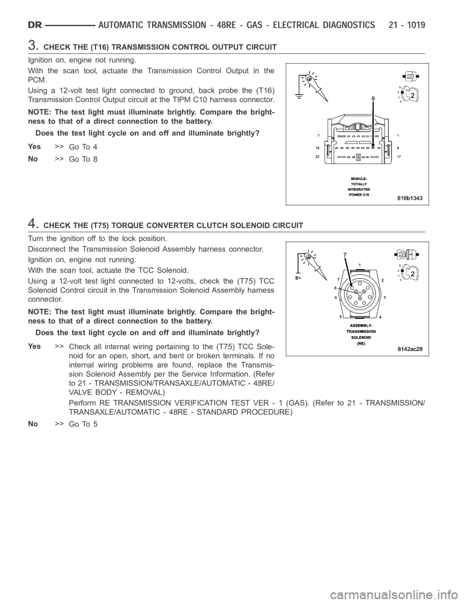
3.CHECK THE (T16) TRANSMISSION CONTROL OUTPUT CIRCUIT
Ignition on, engine not running.
With the scan tool, actuate the Transmission Control Output in the
PCM.
Using a 12-volt test light connected to ground, back probe the (T16)
Transmission Control Output circuit at the TIPM C10 harness connector.
NOTE: The test light must illuminate brightly. Compare the bright-
ness to that of a direct connection to the battery.
Does the test light cycle on and off and illuminate brightly?
Ye s>>
Go To 4
No>>
Go To 8
4.CHECK THE (T75) TORQUE CONVERTER CLUTCH SOLENOID CIRCUIT
Turn the ignition off to the lock position.
Disconnect the Transmission Solenoid Assembly harness connector.
Ignition on, engine not running.
With the scan tool, actuate the TCC Solenoid.
Using a 12-volt test light connected to 12-volts, check the (T75) TCC
Solenoid Control circuit in the Transmission Solenoid Assembly harness
connector.
NOTE: The test light must illuminate brightly. Compare the bright-
ness to that of a direct connection to the battery.
Does the test light cycle on and off and illuminate brightly?
Ye s>>
Check all internal wiring pertaining to the (T75) TCC Sole-
noid for an open, short, and bent or broken terminals. If no
internal wiring problems are found, replace the Transmis-
sion Solenoid Assembly per the Service Information. (Refer
to 21 - TRANSMISSION/TRANSAXLE/AUTOMATIC - 48RE/
VA LV E B O D Y - R E M O VA L )
Perform RE TRANSMISSION VERIFICATION TEST VER - 1 (GAS). (Refer to 21 - TRANSMISSION/
TRANSAXLE/AUTOMATIC - 48RE - STANDARD PROCEDURE)
No>>
Go To 5
Page 3547 of 5267
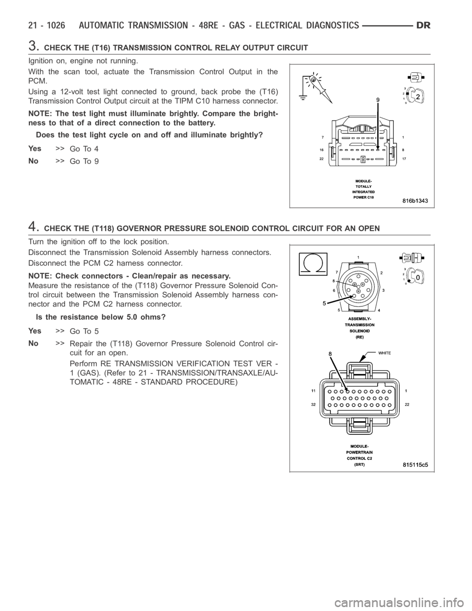
3.CHECK THE (T16) TRANSMISSION CONTROL RELAY OUTPUT CIRCUIT
Ignition on, engine not running.
With the scan tool, actuate the Transmission Control Output in the
PCM.
Using a 12-volt test light connected to ground, back probe the (T16)
Transmission Control Output circuit at the TIPM C10 harness connector.
NOTE: The test light must illuminate brightly. Compare the bright-
ness to that of a direct connection to the battery.
Does the test light cycle on and off and illuminate brightly?
Ye s>>
Go To 4
No>>
Go To 9
4.CHECK THE (T118) GOVERNOR PRESSURE SOLENOID CONTROL CIRCUIT FOR AN OPEN
Turn the ignition off to the lock position.
Disconnect the Transmission Solenoid Assembly harness connectors.
Disconnect the PCM C2 harness connector.
NOTE: Check connectors - Clean/repair as necessary.
Measure the resistance of the (T118) Governor Pressure Solenoid Con-
trol circuit between the Transmission Solenoid Assembly harness con-
nector and the PCM C2 harness connector.
Is the resistance below 5.0 ohms?
Ye s>>
Go To 5
No>>
Repair the (T118) Governor Pressure Solenoid Control cir-
cuit for an open.
Perform RE TRANSMISSION VERIFICATION TEST VER -
1 (GAS). (Refer to 21 - TRANSMISSION/TRANSAXLE/AU-
TOMATIC - 48RE - STANDARD PROCEDURE)
Page 3557 of 5267
2.CHECK IF THE DTC IS CURRENT
Ignition on, engine not running.
With the scan tool, read Engine DTCs.
Record the Freeze Frame data for the reported DTC.
With the scan tool, erase DTCs.
Turn the ignition off to the lock position.
Using the Freeze Frame data recorded earlier, try to duplicate the conditions in which the DTC originally set.
NOTE: It may be necessary to road test the vehicle to duplicate the originalset conditions.
With the scan tool, read Engine DTCs.
Did the DTC reset?
Ye s>>
Go To 3
No>>
Go To 12
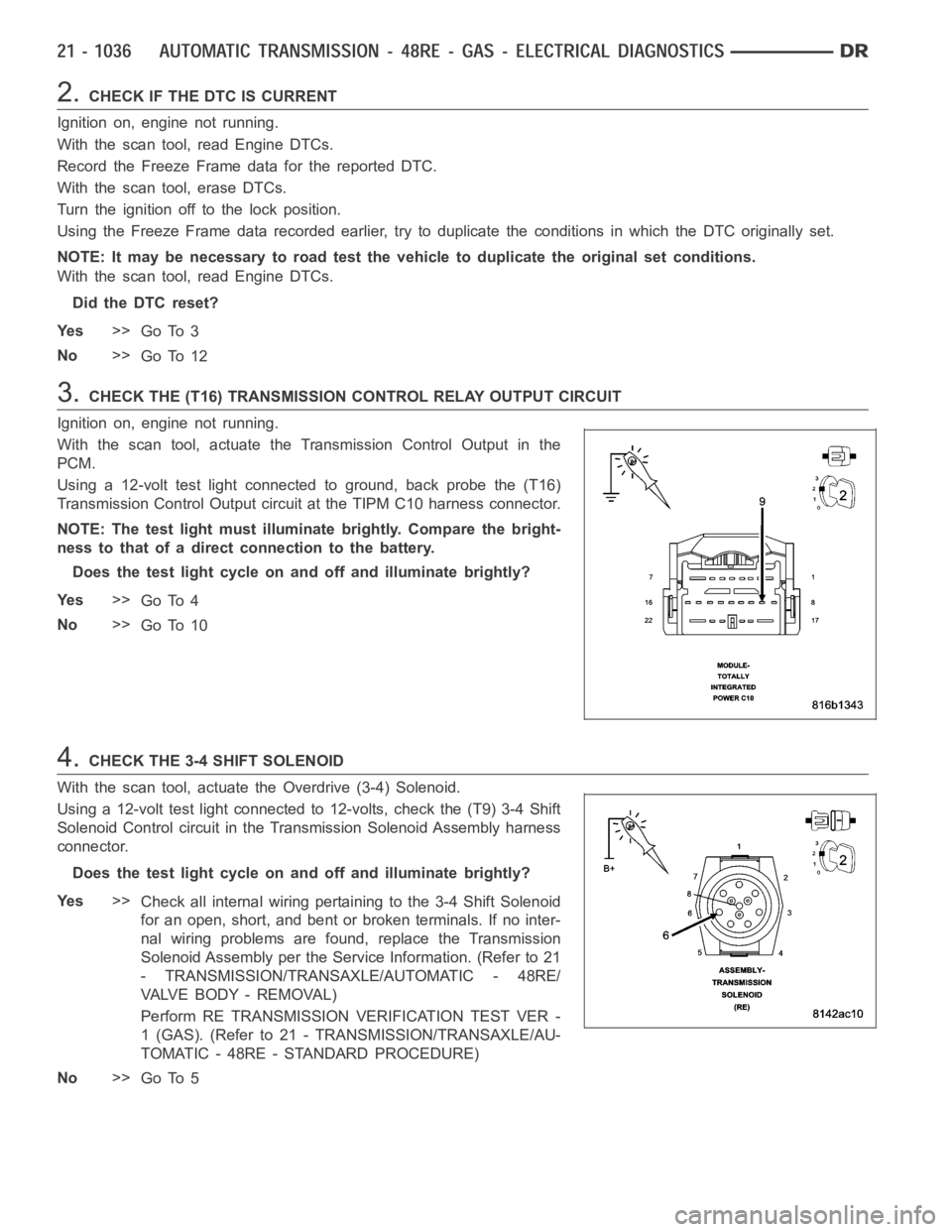
3.CHECK THE (T16) TRANSMISSION CONTROL RELAY OUTPUT CIRCUIT
Ignition on, engine not running.
With the scan tool, actuate the Transmission Control Output in the
PCM.
Using a 12-volt test light connected to ground, back probe the (T16)
Transmission Control Output circuit at the TIPM C10 harness connector.
NOTE: The test light must illuminate brightly. Compare the bright-
ness to that of a direct connection to the battery.
Does the test light cycle on and off and illuminate brightly?
Ye s>>
Go To 4
No>>
Go To 10
4.CHECK THE 3-4 SHIFT SOLENOID
With the scan tool, actuate the Overdrive (3-4) Solenoid.
Using a 12-volt test light connected to 12-volts, check the (T9) 3-4 Shift
Solenoid Control circuit in the Transmission Solenoid Assembly harness
connector.
Does the test light cycle on and off and illuminate brightly?
Ye s>>
Check all internal wiring pertaining to the 3-4 Shift Solenoid
for an open, short, and bent or broken terminals. If no inter-
nal wiring problems are found, replace the Transmission
Solenoid Assembly per the Service Information. (Refer to 21
- TRANSMISSION/TRANSAXLE/AUTOMATIC - 48RE/
VA LV E B O D Y - R E M O VA L )
Perform RE TRANSMISSION VERIFICATION TEST VER -
1 (GAS). (Refer to 21 - TRANSMISSION/TRANSAXLE/AU-
TOMATIC - 48RE - STANDARD PROCEDURE)
No>>
Go To 5
Page 3572 of 5267
When Monitored:
With the ignition on. Battery voltage greater than 10 volts.
Set Condition:
A shorted condition is detected in the TIPM Transmission Control Output circuit.
Possible Causes
(T16) TRANSMISSION CONTROL OUTPUT CIRCUIT SHORTED TO GROUND
TOTALLY INTEGRATED POWER MODULE (TIPM)
Diagnostic Test
1.CHECK IF THE DTC IS ACTIVE
Ignition on, engine not running.
With the scan tool, select View DTCs.
Is the status Active for this DTC?
Ye s>>
Go to 2
No>>
Go to 5
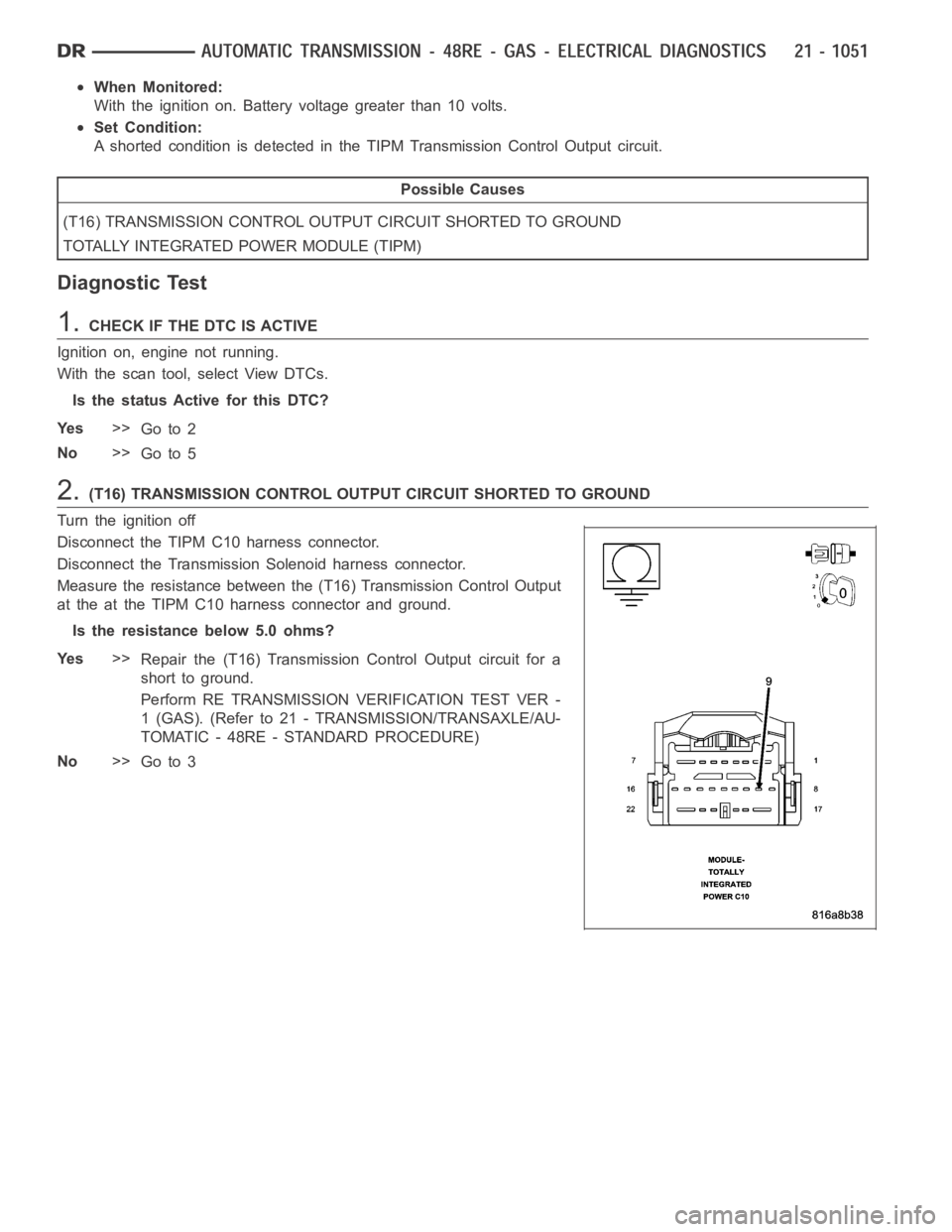
2.(T16) TRANSMISSION CONTROL OUTPUT CIRCUIT SHORTED TO GROUND
Turn the ignition off
Disconnect the TIPM C10 harness connector.
Disconnect the Transmission Solenoid harness connector.
Measure the resistance between the (T16) Transmission Control Output
at the at the TIPM C10 harness connector and ground.
Is the resistance below 5.0 ohms?
Ye s>>
Repair the (T16) Transmission Control Output circuit for a
short to ground.
Perform RE TRANSMISSION VERIFICATION TEST VER -
1 (GAS). (Refer to 21 - TRANSMISSION/TRANSAXLE/AU-
TOMATIC - 48RE - STANDARD PROCEDURE)
No>>
Go to 3