2006 DODGE RAM SRT-10 battery
[x] Cancel search: batteryPage 3306 of 5267
When Monitored:
With the ignition on. Battery voltage greater than 10 volts.
Set Condition:
A shorted condition is detected in the Transmission Control Output circuit.
Possible Causes
(T16) TRANSMISSION CONTROL OUTPUT CIRCUIT SHORT TO GROUND
(T16) TRANSMISSION CONTROL OUTPUT CIRCUIT FOR AN OPEN
TOTALLY INTEGRATED POWER MODULE (TIPM)
Diagnostic Test
1.CHECK IF THE DTC IS ACTIVE
Ignition on, engine not running.
With the scan tool, check TIPM DTCs.
Is the status Active for this DTC?
Ye s>>
Go to 2
No>>
Go to 5
2.CHECK THE (T16) TRANSMISSION CONTROL OUTPUT CIRCUIT SHORT TO GROUND
Turn the ignition off
Disconnect the TIPM C10 harness connector.
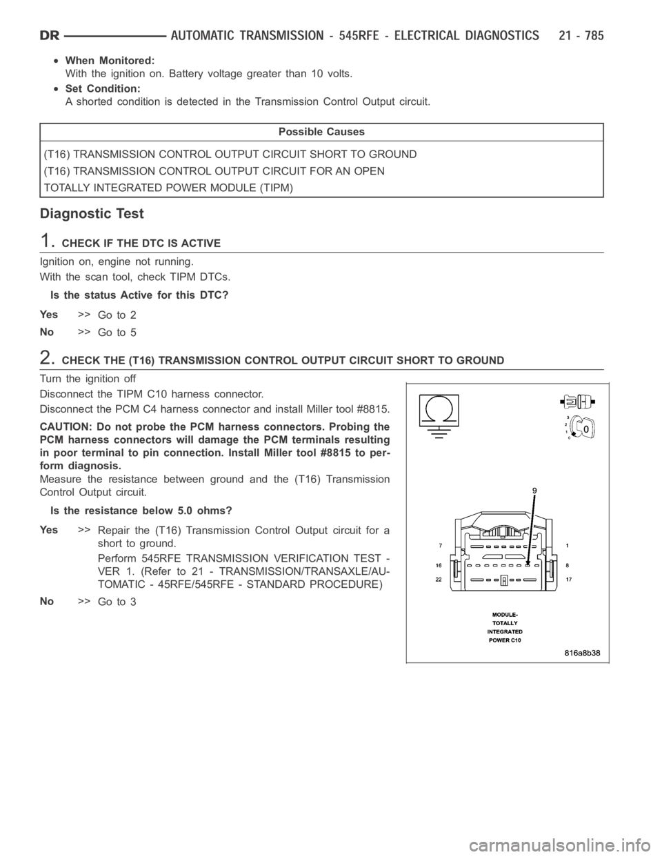
Disconnect the PCM C4 harness connector and install Miller tool #8815.
CAUTION: Do not probe the PCM harness connectors. Probing the
PCM harness connectors will damage the PCM terminals resulting
in poor terminal to pin connection. Install Miller tool #8815 to per-
form diagnosis.
Measure the resistance between ground and the (T16) Transmission
Control Output circuit.
Is the resistance below 5.0 ohms?
Ye s>>
Repair the (T16) Transmission Control Output circuit for a
short to ground.
Perform 545RFE TRANSMISSION VERIFICATION TEST -
VER 1. (Refer to 21 - TRANSMISSION/TRANSAXLE/AU-
TOMATIC - 45RFE/545RFE - STANDARD PROCEDURE)
No>>
Go to 3
Page 3307 of 5267
3.CHECK THE (T16) TRANSMISSION CONTROL OUTPUT CIRCUIT FOR AN OPEN
Turn the ignition off to the lock position.
Connect the TIPM C10 harness connector.
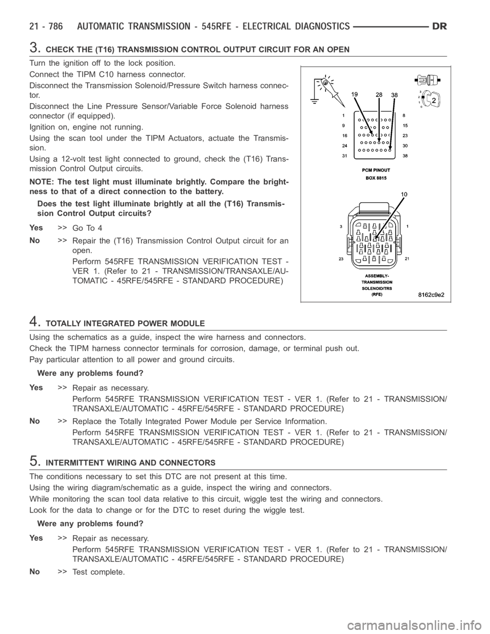
Disconnect the Transmission Solenoid/Pressure Switch harness connec-
tor.
Disconnect the Line Pressure Sensor/Variable Force Solenoid harness
connector (if equipped).
Ignition on, engine not running.
Using the scan tool under the TIPM Actuators, actuate the Transmis-
sion.
Using a 12-volt test light connected to ground, check the (T16) Trans-
mission Control Output circuits.
NOTE: The test light must illuminate brightly. Compare the bright-
ness to that of a direct connection to the battery.
Does the test light illuminate brightly at all the (T16) Transmis-
sion Control Output circuits?
Ye s>>
Go To 4
No>>
Repair the (T16) Transmission Control Output circuit for an
open.
Perform 545RFE TRANSMISSION VERIFICATION TEST -
VER 1. (Refer to 21 - TRANSMISSION/TRANSAXLE/AU-
TOMATIC - 45RFE/545RFE - STANDARD PROCEDURE)
4.TOTALLY INTEGRATED POWER MODULE
Using the schematics as a guide, inspect the wire harness and connectors.
Check the TIPM harness connector terminals for corrosion, damage, or terminal push out.
Pay particular attention to all power and ground circuits.
Were any problems found?
Ye s>>
Repair as necessary.
Perform 545RFE TRANSMISSION VERIFICATION TEST - VER 1. (Refer to 21 - TRANSMISSION/
TRANSAXLE/AUTOMATIC - 45RFE/545RFE - STANDARD PROCEDURE)
No>>
Replace the Totally Integrated Power Module per Service Information.
Perform 545RFE TRANSMISSION VERIFICATION TEST - VER 1. (Refer to 21 - TRANSMISSION/
TRANSAXLE/AUTOMATIC - 45RFE/545RFE - STANDARD PROCEDURE)
5.INTERMITTENT WIRING AND CONNECTORS
The conditions necessary to set this DTC are not present at this time.
Using the wiring diagram/schematic as a guide, inspect the wiring and connectors.
While monitoring the scan tool data relative to this circuit, wiggle test the wiring and connectors.
Look for the data to change or for the DTC to reset during the wiggle test.
Were any problems found?
Ye s>>
Repair as necessary.
Perform 545RFE TRANSMISSION VERIFICATION TEST - VER 1. (Refer to 21 - TRANSMISSION/
TRANSAXLE/AUTOMATIC - 45RFE/545RFE - STANDARD PROCEDURE)
No>>
Te s t c o m p l e t e .
Page 3309 of 5267
When Monitored:
With the ignition on. Battery voltage greater than 10 volts.
Set Condition:
A shorted condition is detected in the TIPM Transmission Control Output circuit.
Possible Causes
(T16) TRANSMISSION CONTROL OUTPUT CIRCUIT SHORT TO VOLTAGE
TOTALLY INTEGRATED POWER MODULE (TIPM)
Diagnostic Test
1.CHECK IF THE DTC IS ACTIVE
Ignition on, engine not running.
With the scan tool, read TIPM DTCs.
Is the status Active for this DTC?
Ye s>>
Go to 2
No>>
Go to 4
2.(T16) TRANSMISSION CONTROL OUTPUT CIRCUIT SHORT TO VOLTAGE
Turn the ignition off to the lock position.
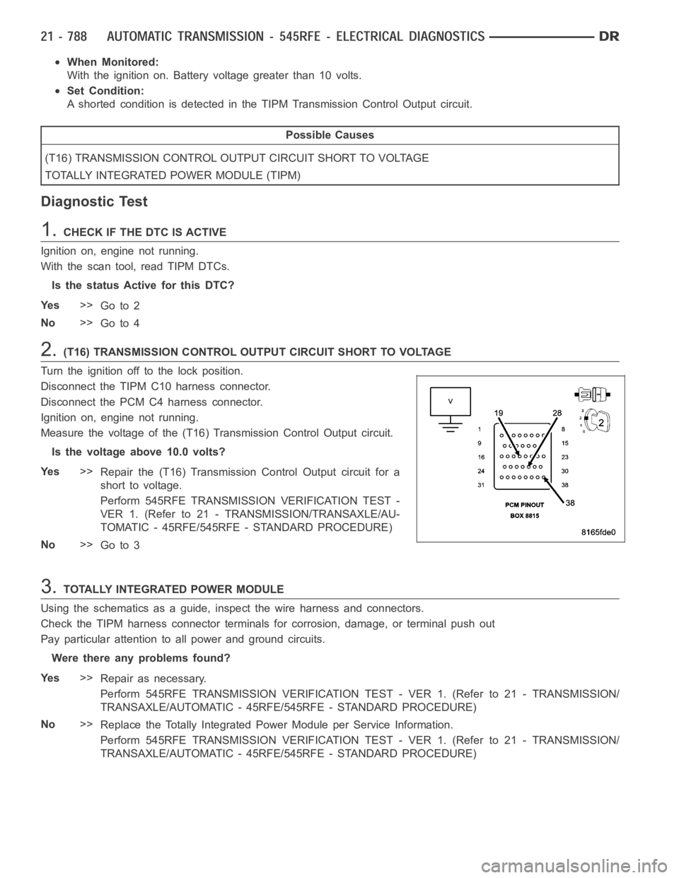
Disconnect the TIPM C10 harness connector.
Disconnect the PCM C4 harness connector.
Ignition on, engine not running.
Measure the voltage of the (T16) Transmission Control Output circuit.
Is the voltage above 10.0 volts?
Ye s>>
Repair the (T16) Transmission Control Output circuit for a
short to voltage.
Perform 545RFE TRANSMISSION VERIFICATION TEST -
VER 1. (Refer to 21 - TRANSMISSION/TRANSAXLE/AU-
TOMATIC - 45RFE/545RFE - STANDARD PROCEDURE)
No>>
Go to 3
3.TOTALLY INTEGRATED POWER MODULE
Using the schematics as a guide, inspect the wire harness and connectors.
Check the TIPM harness connector terminals for corrosion, damage, or terminal push out
Pay particular attention to all power and ground circuits.
Were there any problems found?
Ye s>>
Repair as necessary.
Perform 545RFE TRANSMISSION VERIFICATION TEST - VER 1. (Refer to 21 - TRANSMISSION/
TRANSAXLE/AUTOMATIC - 45RFE/545RFE - STANDARD PROCEDURE)
No>>
Replace the Totally Integrated Power Module per Service Information.
Perform 545RFE TRANSMISSION VERIFICATION TEST - VER 1. (Refer to 21 - TRANSMISSION/
TRANSAXLE/AUTOMATIC - 45RFE/545RFE - STANDARD PROCEDURE)
Page 3312 of 5267
When Monitored:
With the ignition on. Battery voltage greater than 10 volts.
Set Condition:
An open condition of the Transmission Control Output circuit is detected by the Totally Integrated Power Mod-
ule (TIPM).
Possible Causes
(T16) TRANSMISSION CONTROL OUTPUT CIRCUIT OPEN
TOTALLY INTEGRATED POWER MODULE (TIPM)
Diagnostic Test
1.CHECK IF THE DTC IS ACTIVE
Ignition on, engine not running.
With the scan tool, select View DTCs.
Is the status Active for this DTC?
Ye s>>
Go to 2
No>>
Go to 4
2.CHECK THE (T16) TRANSMISSION CONTROL OUTPUT CIRCUIT FOR AN OPEN
Turn the ignition off to the lock position.
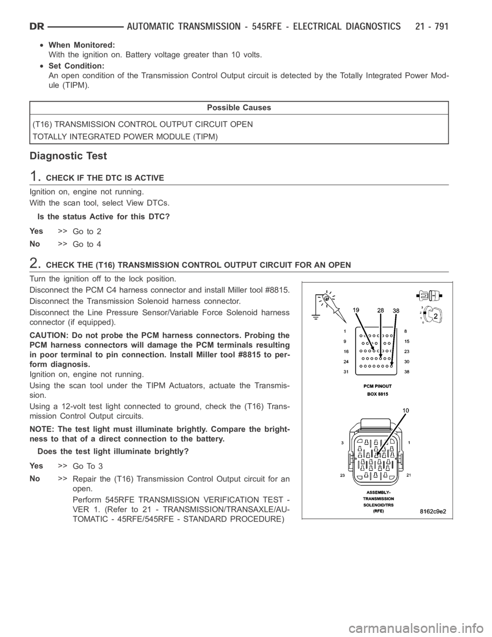
Disconnect the PCM C4 harness connector and install Miller tool #8815.
Disconnect the Transmission Solenoid harness connector.
Disconnect the Line Pressure Sensor/Variable Force Solenoid harness
connector (if equipped).
CAUTION: Do not probe the PCM harness connectors. Probing the
PCM harness connectors will damage the PCM terminals resulting
in poor terminal to pin connection. Install Miller tool #8815 to per-
form diagnosis.
Ignition on, engine not running.
Using the scan tool under the TIPM Actuators, actuate the Transmis-
sion.
Using a 12-volt test light connected to ground, check the (T16) Trans-
mission Control Output circuits.
NOTE: The test light must illuminate brightly. Compare the bright-
ness to that of a direct connection to the battery.
Does the test light illuminate brightly?
Ye s>>
Go To 3
No>>
Repair the (T16) Transmission Control Output circuit for an
open.
Perform 545RFE TRANSMISSION VERIFICATION TEST -
VER 1. (Refer to 21 - TRANSMISSION/TRANSAXLE/AU-
TOMATIC - 45RFE/545RFE - STANDARD PROCEDURE)
Page 3315 of 5267
When Monitored:
With the ignition on. Battery voltage greater than 10 volts.
Set Condition:
An overcurrent condition is detected in the TCM Power Control circuit. OneTrip Fault. Three good trips to turn
off the MIL.
Possible Causes
LINE PRESSURE SENSOR VARIABLE FORCE SOLENOID
SOLENOID/PRESSURE SWITCH ASSEMBLY
POWERTRAIN CONTROL MODULE (PCM)
TOTALLY INTEGRATED POWER MODULE (TIPM)
Diagnostic Test
1.CHECK IF THE DTC IS ACTIVE
Ignition on, engine not running.
With a scan tool, read TIPM DTCs.
Is the DTC active at this time?
Ye s>>
Go To 2
No>>
Go To 5
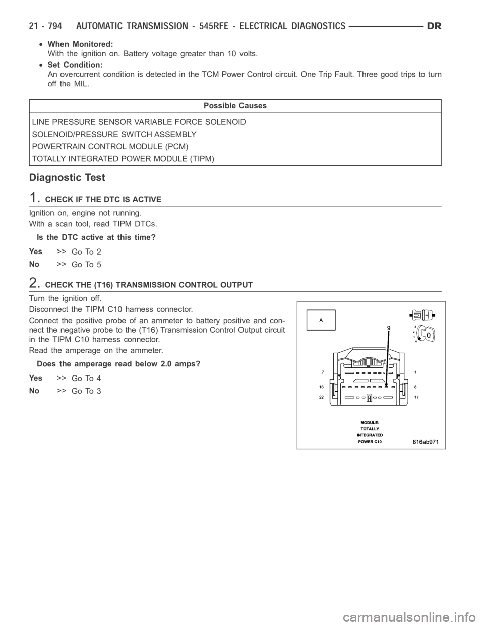
2.CHECK THE (T16) TRANSMISSION CONTROL OUTPUT
Turn the ignition off.
Disconnect the TIPM C10 harness connector.
Connect the positive probe of an ammeter to battery positive and con-
nect the negative probe to the (T16) Transmission Control Output circuit
in the TIPM C10 harness connector.
Read the amperage on the ammeter.
Does the amperage read below 2.0 amps?
Ye s>>
Go To 4
No>>
Go To 3
Page 3316 of 5267
3.CHECK THE PCM
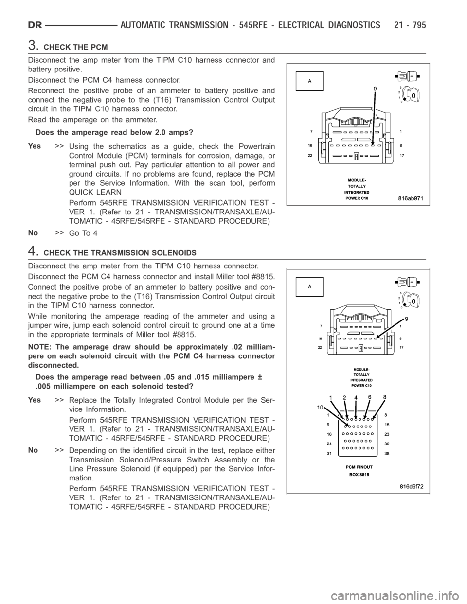
Disconnect the amp meter from the TIPM C10 harness connector and
battery positive.
Disconnect the PCM C4 harness connector.
Reconnect the positive probe of an ammeter to battery positive and
connect the negative probe to the (T16) Transmission Control Output
circuit in the TIPM C10 harness connector.
Read the amperage on the ammeter.
Does the amperage read below 2.0 amps?
Ye s>>
Using the schematics as a guide, check the Powertrain
Control Module (PCM) terminals for corrosion, damage, or
terminal push out. Pay particular attention to all power and
ground circuits. If no problems are found, replace the PCM
per the Service Information.With the scan tool, perform
QUICK LEARN
Perform 545RFE TRANSMISSION VERIFICATION TEST -
VER 1. (Refer to 21 - TRANSMISSION/TRANSAXLE/AU-
TOMATIC - 45RFE/545RFE - STANDARD PROCEDURE)
No>>
Go To 4
4.CHECK THE TRANSMISSION SOLENOIDS
Disconnect the amp meter from theTIPM C10 harness connector.
Disconnect the PCM C4 harness connector and install Miller tool #8815.
Connect the positive probe of an ammeter to battery positive and con-
nect the negative probe to the (T16) Transmission Control Output circuit
in the TIPM C10 harness connector.
While monitoring the amperage reading of the ammeter and using a
jumper wire, jump each solenoid control circuit to ground one at a time
in the appropriate terminals of Miller tool #8815.
NOTE: The amperage draw should be approximately .02 milliam-
pere on each solenoid circuit with the PCM C4 harness connector
disconnected.
Does the amperage read between .05 and .015 milliampere ±
.005 milliampere on each solenoid tested?
Ye s>>
Replace the Totally Integrated Control Module per the Ser-
vice Information.
Perform 545RFE TRANSMISSION VERIFICATION TEST -
VER 1. (Refer to 21 - TRANSMISSION/TRANSAXLE/AU-
TOMATIC - 45RFE/545RFE - STANDARD PROCEDURE)
No>>
Depending on the identified circuit in the test, replace either
Transmission Solenoid/Pressure Switch Assembly or the
Line Pressure Solenoid (if equipped) per the Service Infor-
mation.
Perform 545RFE TRANSMISSION VERIFICATION TEST -
VER 1. (Refer to 21 - TRANSMISSION/TRANSAXLE/AU-
TOMATIC - 45RFE/545RFE - STANDARD PROCEDURE)
Page 3318 of 5267
P1684-BATTERY WAS DISCONNECTED
For a complete wiring diagramRefer to Section 8W.
When Monitored:
Whenever the ignition is in the Run/Start position.
Set Condition:
This DTC will set whenever Powertrain Control Module is disconnected fromFused B(+) or ground. It will also
be set using the scan tool to perform a Battery Disconnect and/or Quick Learn procedure.
Possible Causes
BATTERY WAS DISCONNECTED
SCAN TOOL BATTERY DISCONNECT PERFORMED
PCM WAS REPLACED OR DISCONNECTED
QUICK LEARN WAS PERFORMED
Always perform the 45RFE/545RFE Pre-Diagnostic Troubleshooting Procedure before proceeding. (Refer to
21 - TRANSMISSION/TRANSAXLE/AUTOMATIC - 45RFE/545RFE - STANDARD PROCEDURE)
Theory of Operation
The PCM uses a battery backed RAM (Random Access Memory) is used to maintainsome learned values. When
the battery B(+) is disconnected, the memory is lost. When the B(+) is restored, this memory loss is detected by the
Transmission Control System. The DTC is set and the learned values are initialized to known constants or previ-
ously learned values from EEPROM (Electronic Erasable Programmable ReadOnly Memory). This results in the
reinitialization of some parameters.
Diagnostic Test
1.POSSIBLE CAUSES
This DTC is an informational DTC only.
This DTC is set due to a momentary loss of power and/or the ground circuits tothe PCM.
Below are a list of possible causes associated with this DTC.
Battery was disconnected.
The BATTERY DISCONNECT feature on the scan tool was performed.
The QUICK LEARN feature on the scan tool was performed.
PCM was replaced or disconnected.
Were any of the above possible causes performed?
Ye s>>
This is the cause of the DTC. Erase the DTC and return vehicle to customer.
Perform 45RFE/545RFE TRANSMISSION VERIFICATION TEST - VER 1. (Refer to 21- TRANSMIS-
SION/TRANSAXLE/AUTOMATIC - 45RFE/545RFE - STANDARD PROCEDURE)
No>>
Go To 2
Page 3340 of 5267
3.L/R CLUTCH CIRCUIT LEAKS IN THE VALVE BODY
Turn the ignition off to the lock position.
Remove the transmission oil pan per the Service Information.
Remove the valve body per the service information.
Check condition of the L/R accumulator springs.
Look for possible leak paths into the L/R clutch hydraulics circuit withinthe valve body.
Were any problems found?
Ye s>>
Repair as necessary.
Perform 45RFE/545RFE TRANSMISSION VERIFICATION TEST - VER 1. (Refer to 21- TRANSMIS-
SION/TRANSAXLE/AUTOMATIC - 45RFE/545RFE - STANDARD PROCEDURE)
No>>
Go To 4
4.AIR CHECK L/R CLUTCH CIRCUITS
Perform an air check on the L/R Clutch circuit per the Service Information.
Watch and listen for L/R Clutch piston movement.
Does the L/R piston stroke and return properly?
Ye s>>
Replace the Transmission/TRS Solenoid Assembly per the service information. With the scan tool, per-
form Quick Learn.
Perform 45RFE/545RFE TRANSMISSION VERIFICATION TEST - VER 1. (Refer to 21- TRANSMIS-
SION/TRANSAXLE/AUTOMATIC - 45RFE/545RFE - STANDARD PROCEDURE)
No>>
Repair internal transmission as necessary. Pay attention to the components related to the L/R clutch. A
broken or weak L/R clutch return spring, Accumulator Spring, and/or dislocated snap ring could cause
this problem.
Perform 45RFE/545RFE TRANSMISSION VERIFICATION TEST - VER 1. (Refer to 21- TRANSMIS-
SION/TRANSAXLE/AUTOMATIC - 45RFE/545RFE - STANDARD PROCEDURE)
5.VERIFY PCM OPERATION
NOTE: The TRANS TEMP DEG must be at least 43° C or 110° F before performing thefollowing steps.
Perform eight learnable starts. A learnable start is defined as follows: Start engine. From a standstill, accelerate
lightly to 80 Kmh or 50 MPH, then brake lightly to a stop. Turn off engine.
With the scan tool, record the CL VOL INDEX (CVI) for all clutches
With the scan tool, perform a BATTERY DISCONNECT.
With the scan tool, read the CVI’s and compare them to the readings recordedbefore the BATTERY DISCONNECT.
Are any of the CVI’s less than 5 or different than before the BATTERY DISCONNECT?
Ye s>>
Using the schematics as a guide, check the Powertrain Control Module (PCM)terminals for corrosion,
damage, or terminal push out. Pay particular attention to all power and ground circuits. If no problems
are found, replace the PCM per the Service Information. With the scan tool,perform QUICK LEARN.
Perform 45RFE/545RFE TRANSMISSION VERIFICATION TEST - VER 1. (Refer to 21- TRANSMIS-
SION/TRANSAXLE/AUTOMATIC - 45RFE/545RFE - STANDARD PROCEDURE)
No>>
Te s t C o m p l e t e .