2006 DODGE RAM SRT-10 battery
[x] Cancel search: batteryPage 3103 of 5267
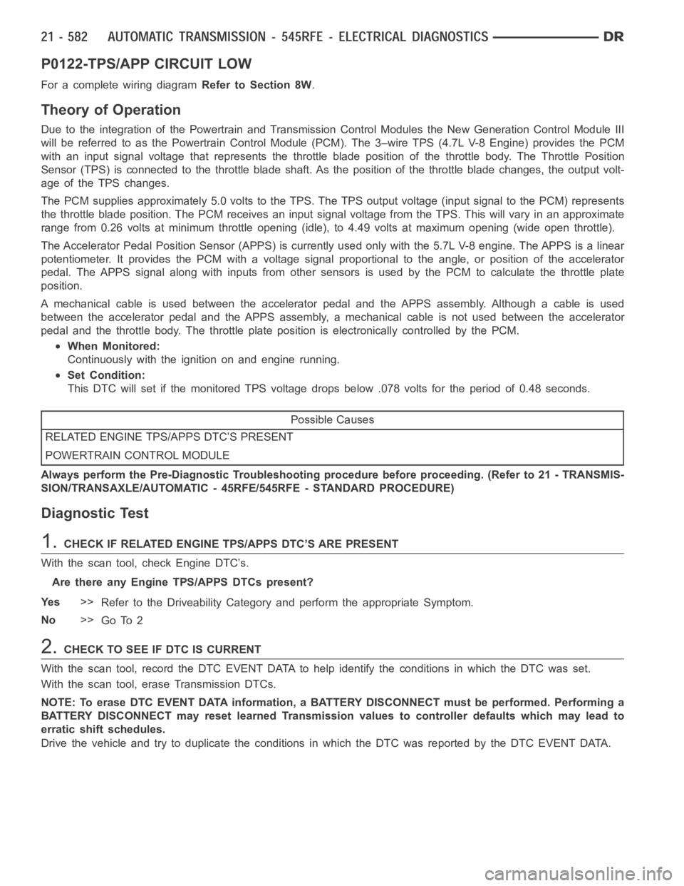
P0122-TPS/APP CIRCUIT LOW
For a complete wiring diagramRefer to Section 8W.
Theory of Operation
Due to the integration of the Powertrain and Transmission Control Modulesthe New Generation Control Module III
will be referred to as the Powertrain Control Module (PCM). The 3–wire TPS (4.7L V-8 Engine) provides the PCM
with an input signal voltage that represents the throttle blade position of the throttle body. The Throttle Position
Sensor (TPS) is connected to the throttle blade shaft. As the position of the throttle blade changes, the output volt-
age of the TPS changes.
The PCM supplies approximately 5.0 volts to the TPS. The TPS output voltage(input signal to the PCM) represents
the throttle blade position. The PCM receives an input signal voltage fromthe TPS. This will vary in an approximate
range from 0.26 volts at minimum throttle opening (idle), to 4.49 volts at maximum opening (wide open throttle).
The Accelerator Pedal Position Sensor (APPS) is currently used only with the 5.7L V-8 engine. The APPS is a linear
potentiometer. It provides the PCM with a voltage signal proportional to the angle, or position of the accelerator
pedal. The APPS signal along with inputs from other sensors is used by the PCM to calculate the throttle plate
position.
A mechanical cable is used between the accelerator pedal and the APPS assembly. Although a cable is used
between the accelerator pedal and the APPS assembly, a mechanical cable isnot used between the accelerator
pedal and the throttle body. The throttle plate position is electronically controlled by the PCM.
When Monitored:
Continuously with the ignition on and engine running.
Set Condition:
This DTC will set if the monitored TPS voltage drops below .078 volts for theperiod of 0.48 seconds.
Possible Causes
RELATED ENGINE TPS/APPS DTC’S PRESENT
POWERTRAIN CONTROL MODULE
Always perform the Pre-Diagnostic Troubleshooting procedure before proceeding. (Refer to 21 - TRANSMIS-
SION/TRANSAXLE/AUTOMATIC - 45RFE/545RFE - STANDARD PROCEDURE)
Diagnostic Test
1.CHECK IF RELATED ENGINE TPS/APPS DTC’S ARE PRESENT
With the scan tool, check Engine DTC’s.
Are there any Engine TPS/APPS DTCs present?
Ye s>>
Refer to the Driveability Category and perform the appropriate Symptom.
No>>
Go To 2
2.CHECK TO SEE IF DTC IS CURRENT
With the scan tool, record the DTC EVENT DATA to help identify the conditionsinwhichtheDTCwasset.
With the scan tool, erase Transmission DTCs.
NOTE: To erase DTC EVENT DATA information, a BATTERY DISCONNECT must be performed. Performing a
BATTERY DISCONNECT may reset learned Transmission values to controller defaults which may lead to
erratic shift schedules.
Drive the vehicle and try to duplicate the conditions in which the DTC was reported by the DTC EVENT DATA.
Page 3105 of 5267
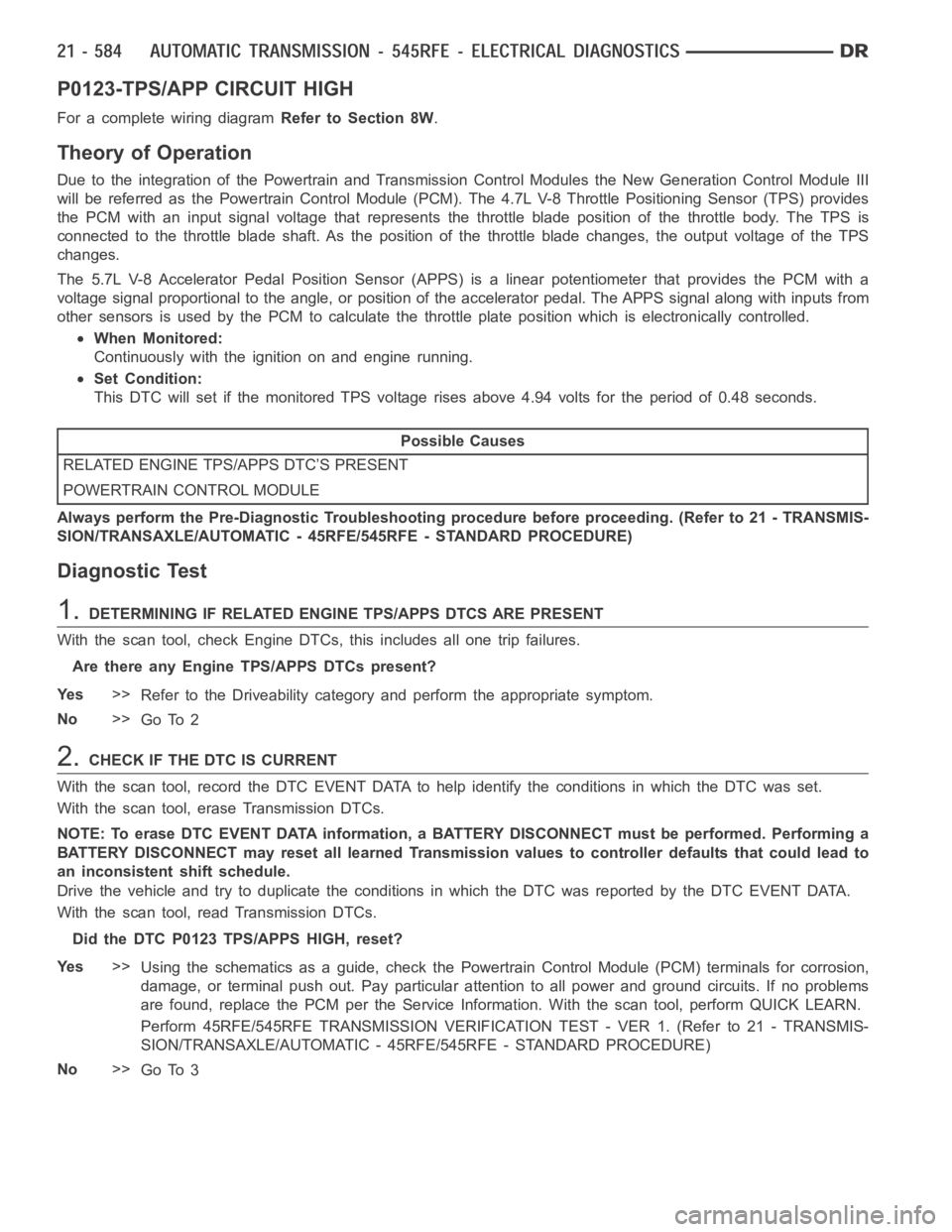
P0123-TPS/APP CIRCUIT HIGH
For a complete wiring diagramRefer to Section 8W.
Theory of Operation
Due to the integration of the Powertrain and Transmission Control Modulesthe New Generation Control Module III
will be referred as the Powertrain Control Module (PCM). The 4.7L V-8 Throttle Positioning Sensor (TPS) provides
the PCM with an input signal voltage that represents the throttle blade position of the throttle body. The TPS is
connected to the throttle blade shaft. As the position of the throttle blade changes, the output voltage of the TPS
changes.
The 5.7L V-8 Accelerator Pedal Position Sensor (APPS) is a linear potentiometer that provides the PCM with a
voltage signal proportional to the angle, or position of the accelerator pedal. The APPS signal along with inputs from
other sensors is used by the PCM to calculate the throttle plate position which is electronically controlled.
When Monitored:
Continuously with the ignition on and engine running.
Set Condition:
This DTC will set if the monitored TPS voltage rises above 4.94 volts for theperiod of 0.48 seconds.
Possible Causes
RELATED ENGINE TPS/APPS DTC’S PRESENT
POWERTRAIN CONTROL MODULE
Always perform the Pre-Diagnostic Troubleshooting procedure before proceeding. (Refer to 21 - TRANSMIS-
SION/TRANSAXLE/AUTOMATIC - 45RFE/545RFE - STANDARD PROCEDURE)
Diagnostic Test
1.DETERMINING IF RELATED ENGINE TPS/APPS DTCS ARE PRESENT
With the scan tool, check Engine DTCs, this includes all one trip failures.
Are there any Engine TPS/APPS DTCs present?
Ye s>>
Refer to the Driveability category and perform the appropriate symptom.
No>>
Go To 2
2.CHECK IF THE DTC IS CURRENT
With the scan tool, record the DTC EVENT DATA to help identify the conditionsinwhichtheDTCwasset.
With the scan tool, erase Transmission DTCs.
NOTE: To erase DTC EVENT DATA information, a BATTERY DISCONNECT must be performed. Performing a
BATTERY DISCONNECT may reset all learned Transmission values to controller defaults that could lead to
an inconsistent shift schedule.
Drive the vehicle and try to duplicate the conditions in which the DTC was reported by the DTC EVENT DATA.
With the scan tool, read Transmission DTCs.
Did the DTC P0123 TPS/APPS HIGH, reset?
Ye s>>
Using the schematics as a guide, check the Powertrain Control Module (PCM)terminals for corrosion,
damage, or terminal push out. Pay particular attention to all power and ground circuits. If no problems
are found, replace the PCM per the Service Information. With the scan tool,perform QUICK LEARN.
Perform 45RFE/545RFE TRANSMISSION VERIFICATION TEST - VER 1. (Refer to 21- TRANSMIS-
SION/TRANSAXLE/AUTOMATIC - 45RFE/545RFE - STANDARD PROCEDURE)
No>>
Go To 3
Page 3107 of 5267
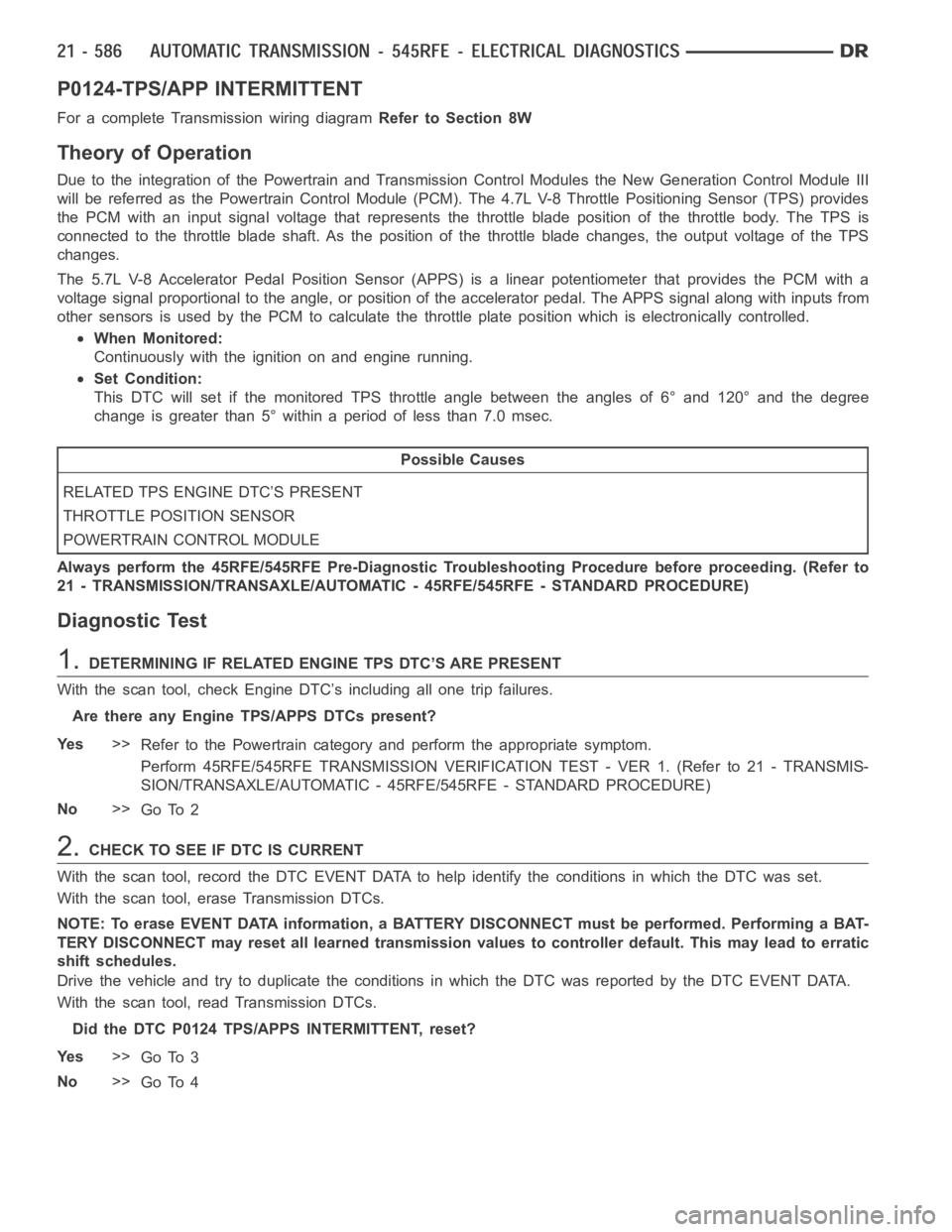
P0124-TPS/APP INTERMITTENT
For a complete Transmission wiring diagramRefer to Section 8W
Theory of Operation
Due to the integration of the Powertrain and Transmission Control Modulesthe New Generation Control Module III
will be referred as the Powertrain Control Module (PCM). The 4.7L V-8 Throttle Positioning Sensor (TPS) provides
the PCM with an input signal voltage that represents the throttle blade position of the throttle body. The TPS is
connected to the throttle blade shaft. As the position of the throttle blade changes, the output voltage of the TPS
changes.
The 5.7L V-8 Accelerator Pedal Position Sensor (APPS) is a linear potentiometer that provides the PCM with a
voltage signal proportional to the angle, or position of the accelerator pedal. The APPS signal along with inputs from
other sensors is used by the PCM to calculate the throttle plate position which is electronically controlled.
When Monitored:
Continuously with the ignition on and engine running.
Set Condition:
This DTC will set if the monitored TPS throttle angle between the angles of 6° and 120° and the degree
change is greater than 5° within a period of less than 7.0 msec.
Possible Causes
RELATED TPS ENGINE DTC’S PRESENT
THROTTLE POSITION SENSOR
POWERTRAIN CONTROL MODULE
Always perform the 45RFE/545RFE Pre-Diagnostic Troubleshooting Procedure before proceeding. (Refer to
21 - TRANSMISSION/TRANSAXLE/AUTOMATIC - 45RFE/545RFE - STANDARD PROCEDURE)
Diagnostic Test
1.DETERMINING IF RELATED ENGINE TPS DTC’S ARE PRESENT
With the scan tool, check Engine DTC’s including all one trip failures.
Are there any Engine TPS/APPS DTCs present?
Ye s>>
Refer to the Powertrain category and perform the appropriate symptom.
Perform 45RFE/545RFE TRANSMISSION VERIFICATION TEST - VER 1. (Refer to 21- TRANSMIS-
SION/TRANSAXLE/AUTOMATIC - 45RFE/545RFE - STANDARD PROCEDURE)
No>>
Go To 2
2.CHECK TO SEE IF DTC IS CURRENT
With the scan tool, record the DTC EVENT DATA to help identify the conditionsinwhichtheDTCwasset.
With the scan tool, erase Transmission DTCs.
NOTE: To erase EVENT DATA information, a BATTERY DISCONNECT must be performed. Performing a BAT-
TERY DISCONNECT may reset all learned transmission values to controller default. This may lead to erratic
shift schedules.
Drive the vehicle and try to duplicate the conditions in which the DTC was reported by the DTC EVENT DATA.
With the scan tool, read Transmission DTCs.
Did the DTC P0124 TPS/APPS INTERMITTENT, reset?
Ye s>>
Go To 3
No>>
Go To 4
Page 3110 of 5267

P0562-BATTERY VOLTAGE LOW
For a complete wiring diagramRefer to Section 8W.
Page 3111 of 5267
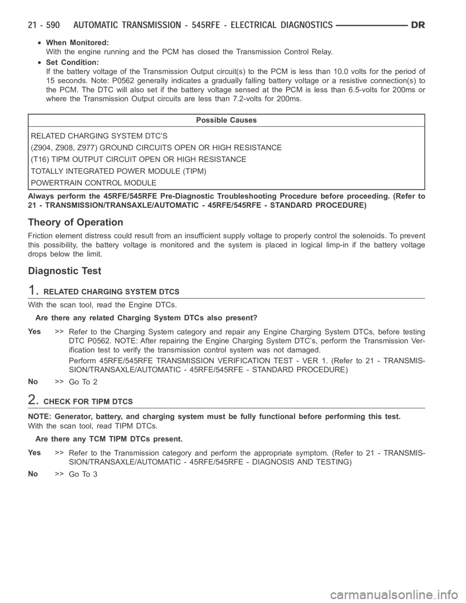
When Monitored:
With the engine running and the PCM has closed the Transmission Control Relay.
Set Condition:
If the battery voltage of the Transmission Output circuit(s) to the PCM is less than 10.0 volts for the period of
15 seconds. Note: P0562 generally indicates a gradually falling battery voltage or a resistive connection(s) to
the PCM. The DTC will also set if the battery voltage sensed at the PCM is lessthan 6.5-volts for 200ms or
where the Transmission Output circuits are less than 7.2-volts for 200ms.
Possible Causes
RELATED CHARGING SYSTEM DTC’S
(Z904, Z908, Z977) GROUND CIRCUITS OPEN OR HIGH RESISTANCE
(T16) TIPM OUTPUT CIRCUIT OPEN OR HIGH RESISTANCE
TOTALLY INTEGRATED POWER MODULE (TIPM)
POWERTRAIN CONTROL MODULE
Always perform the 45RFE/545RFE Pre-Diagnostic Troubleshooting Procedure before proceeding. (Refer to
21 - TRANSMISSION/TRANSAXLE/AUTOMATIC - 45RFE/545RFE - STANDARD PROCEDURE)
Theory of Operation
Friction element distress could result from an insufficient supply voltage to properly control the solenoids. To prevent
this possibility, the battery voltage is monitored and the system is placed in logical limp-in if the battery voltage
drops below the limit.
Diagnostic Test
1.RELATED CHARGING SYSTEM DTCS
With the scan tool, read the Engine DTCs.
Are there any related Charging System DTCs also present?
Ye s>>
Refer to the Charging System category and repair any Engine Charging System DTCs, before testing
DTC P0562. NOTE: After repairing the Engine Charging System DTC’s, perform the Transmission Ver-
ification test to verify the transmission control systemwas not damaged.
Perform 45RFE/545RFE TRANSMISSION VERIFICATION TEST - VER 1. (Refer to 21- TRANSMIS-
SION/TRANSAXLE/AUTOMATIC - 45RFE/545RFE - STANDARD PROCEDURE)
No>>
Go To 2
2.CHECK FOR TIPM DTCS
NOTE: Generator, battery, and charging system must be fully functional before performing this test.
With the scan tool, read TIPM DTCs.
Are there any TCM TIPM DTCs present.
Ye s>>
Refer to the Transmission category and perform the appropriate symptom. (Refer to 21 - TRANSMIS-
SION/TRANSAXLE/AUTOMATIC - 45RFE/545RFE - DIAGNOSIS AND TESTING)
No>>
Go To 3
Page 3112 of 5267
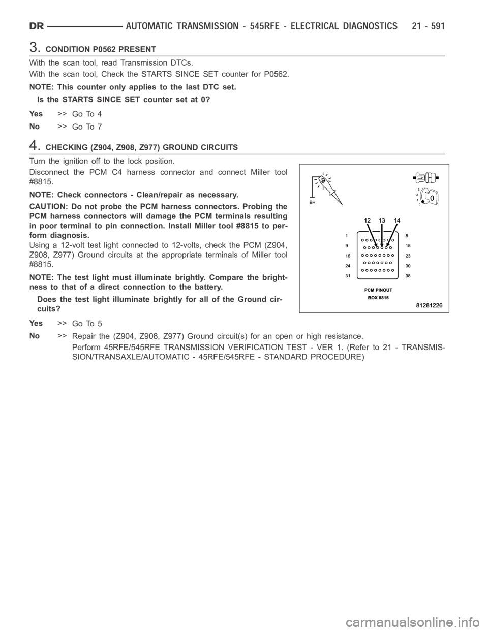
3.CONDITION P0562 PRESENT
With the scan tool, read Transmission DTCs.
With the scan tool, Check the STARTS SINCE SET counter for P0562.
NOTE: This counter only applies to the last DTC set.
Is the STARTS SINCE SET counter set at 0?
Ye s>>
Go To 4
No>>
Go To 7
4.CHECKING (Z904, Z908, Z977) GROUND CIRCUITS
Turn the ignition off to the lock position.
Disconnect the PCM C4 harness connector and connect Miller tool
#8815.
NOTE: Check connectors - Clean/repair as necessary.
CAUTION: Do not probe the PCM harness connectors. Probing the
PCM harness connectors will damage the PCM terminals resulting
in poor terminal to pin connection. Install Miller tool #8815 to per-
form diagnosis.
Using a 12-volt test light connected to 12-volts, check the PCM (Z904,
Z908, Z977) Ground circuits at the appropriate terminals of Miller tool
#8815.
NOTE: The test light must illuminate brightly. Compare the bright-
ness to that of a direct connection to the battery.
Does the test light illuminate brightly for all of the Ground cir-
cuits?
Ye s>>
Go To 5
No>>
Repair the (Z904, Z908, Z977) Ground circuit(s) for an open or high resistance.
Perform 45RFE/545RFE TRANSMISSION VERIFICATION TEST - VER 1. (Refer to 21- TRANSMIS-
SION/TRANSAXLE/AUTOMATIC - 45RFE/545RFE - STANDARD PROCEDURE)
Page 3147 of 5267
P0725-ENGINE SPEED SENSOR CIRCUIT
For a complete wiring diagramRefer to Section 8W.
When Monitored:
Continuously every 7 msec with the ignition on and engine running.
Set Condition:
This DTC will set when the calculated engine speed is less than 390 RPM with the engine running, or greater
than 8000 RPM, for the period of 2.0 seconds. The PCM will place the Transmission in Limp-in when this DTC
is set.Note: This is not a Transmission Input Speed Sensor DTC.
Possible Causes
RELATED ENGINE DTC’S PRESENT
CRANK POSITION SENSOR OR WIRING
POWERTRAIN CONTROL MODULE
Always perform the 45RFE/545RFE Pre-Diagnostic Troubleshooting Procedure before proceeding. (Refer to
21 - TRANSMISSION/TRANSAXLE/AUTOMATIC - 45RFE/545RFE - STANDARD PROCEDURE)
Theory of Operation
The Transmission Control System calculates the engine RPM by directly reading the engine crank position sensor.
It compares the calculated value to the engine speed sensor signal transmitted from the Engine Control System
over the controllers internal BUS. The calculated engine RPM is also comparedtoaminimumandamaximum
value.Note: Due to the integration of the Powertrain Control Module (PCM) and Transmission Control Mod-
ule (TCM), BUS communication between the modules is internal and unserviceable.
Diagnostic Test
1.CHECKFORRELATEDENGINEDTCS
NOTE: This is not a Transmission Input Speed Sensor DTC.
Ignition on, engine not running.
With the scan tool, read all Engine DTCs. This includes any active or storedor one trip DTCs.
Are there any engine RPM related DTCs present?
Ye s>>
Refer to the Powertrain category and perform the appropriate symptom.
Perform 45RFE/545RFE TRANSMISSION VERIFICATION TEST - VER 1. (Refer to 21- TRANSMIS-
SION/TRANSAXLE/AUTOMATIC - 45RFE/545RFE - STANDARD PROCEDURE)
No>>
Go To 2
2.CHECK IF DTC IS CURRENT
Ignition on, engine not running.
With a scan tool, read and record all DTC EVENT DATA.
Withthescantool,eraseallactiveandstoredtransmissionDTCs.(Note:it may be necessary to perform a battery
disconnect with the scan tool to clear DTC EVENT DATA.)
Using the DTC EVENT DATA, duplicate theconditions in which the original DTCset.
With the scan tool, read transmission and engine DTCs.
NOTE: Refer to all engine DTCs first in the following question.
Pick the answer below that best describes your findings, (this includes one trip failures).
Transmission DTC P0725 set
Using the schematics as a guide, check the Powertrain Control Module (PCM)terminals for corrosion,
damage, or terminal push out. Also check the Crank Position sensor and wiring. Pay particular attention
Page 3272 of 5267

P0890-SWITCHED BATTERY
For a complete wiring diagramRefer to Section 8W.