2006 DODGE RAM SRT-10 battery
[x] Cancel search: batteryPage 2593 of 5267
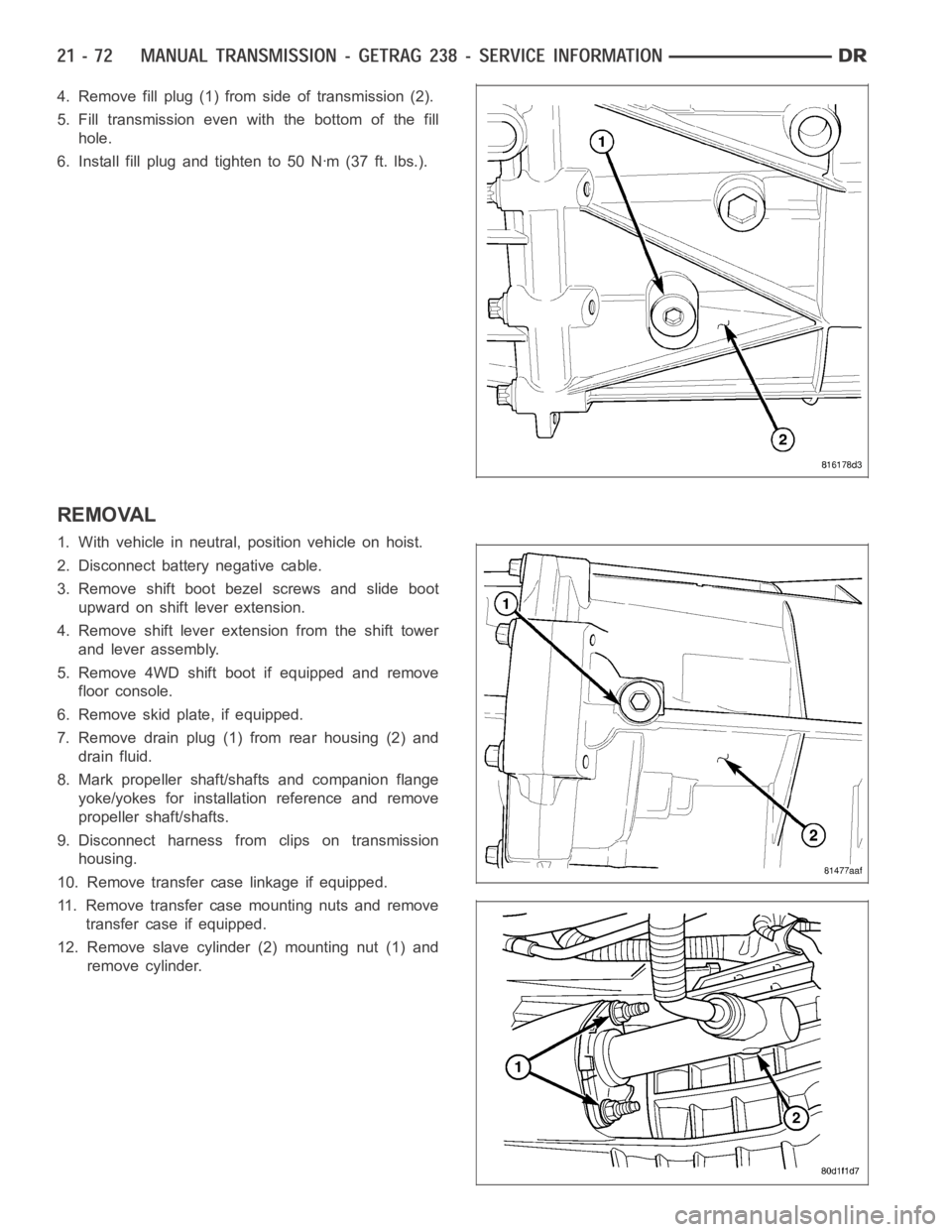
4. Remove fill plug (1) from side of transmission (2).
5. Fill transmission even with the bottom of the fill
hole.
6. Install fill plug and tighten to 50 Nꞏm (37 ft. lbs.).
REMOVAL
1. With vehicle in neutral, position vehicle on hoist.
2. Disconnect battery negative cable.
3. Remove shift boot bezel screws and slide boot
upward on shift lever extension.
4. Remove shift lever extension from the shift tower
and lever assembly.
5. Remove 4WD shift boot if equipped and remove
floor console.
6. Remove skid plate, if equipped.
7. Remove drain plug (1) from rear housing (2) and
drain fluid.
8. Mark propeller shaft/shafts and companion flange
yoke/yokes for installation reference and remove
propeller shaft/shafts.
9. Disconnect harness from clips on transmission
housing.
10. Remove transfer case linkage if equipped.
11. Remove transfer case mounting nuts and remove
transfer case if equipped.
12. Remove slave cylinder (2) mounting nut (1) and
remove cylinder.
Page 2724 of 5267
page page
AUTOMATIC TRANSMISSION 42RLE -
ELECTRICAL DIAGNOSTICS
DIAGNOSIS AND TESTING
P0122-TPS/APP CIRCUIT LOW............. 205
P0123-TPS/APP CIRCUIT HIGH............. 207
P0124-TPS/APP INTERMITTENT ............ 209
P0218-HIGH TEMPERATURE OPERATION
A C T I VAT E D................................ 211
P0562-BATTERY VOLTAGE LOW ............ 213
P0602-CONTROL MODULE PROGRAMMING
ERROR/NOT PROGRAMMED............... 217
P0604-INTERNAL CONTROL MODULE RAM . 218
P0605-INTERNAL CONTROL MODULE ROM . 219
P0613-INTERNAL TRANSMISSION
PROCESSOR.............................. 220
P0706-TRANSMISSION RANGE SENSOR
RATIONALITY............................. 221
P0711-TRANSMISSION TEMPERATURE
SENSOR PERFORMANCE.................. 225
P0712-TRANSMISSION TEMPERATURE
SENSOR LOW............................. 228
P0713-TRANSMISSION TEMPERATURE
SENSOR HIGH............................ 231
P0714-TRANSMISSION TEMPERATURE
SENSOR INTERMITTENT................... 235
P0715-INPUT SPEED SENSOR 1 CIRCUIT . . . 238
P0720-OUTPUT SPEED SENSOR CIRCUIT . . 243
P0725-ENGINE SPEED SENSOR CIRCUIT . . . 248
P0731-GEAR RATIO ERROR IN 1ST ......... 250
P0732-GEAR RATIO ERROR IN 2ND ........ 252
P0733-GEAR RATIO ERROR IN 3RD ........ 254
P0734-GEAR RATIO ERROR IN 4TH ........ 256
P0736-GEAR RATIO ERROR IN REVERSE . . . 258
P0740-TCC OUT OF RANGE ................ 260
P0750-LR SOLENOID CIRCUIT............. 262
P0755-2/4 SOLENOID CIRCUIT ............. 266
P0760-OD SOLENOID CIRCUIT ............. 270
P0765-UD SOLENOID CIRCUIT ............. 274
P0841-LR PRESSURE SWITCH
RATIONALITY............................. 279
P0845-2/4 HYDRAULIC PRESSURE TEST . . . 284
P0846-2/4 PRESSURE SWITCH
RATIONALITY............................. 289
P0868-LINE PRESSURE LOW .............. 294
P0869-LINE PRESSURE HIGH .............. 300
P0870-OD HYDRAULIC PRESSURE TEST . . . 306P0871-OD PRESSURE SWITCH
RATIONALITY.............................. 311
P0882-TCM POWER INPUT LOW ........... 316
P0883-TCM POWER INPUT HIGH ........... 320
P0884-POWER UPAT SPEED .............. 324
P0890-SWITCHED BATTERY ............... 325
P0897-TRANSMISSION FLUID
DETERIORATED........................... 329
P0932-LINE PRESSURE SENSOR CIRCUIT . . 330
P0934-LINE PRESSURE SENSOR CIRCUIT
LOW...................................... 333
P0935-LINE PRESSURE SENSOR CIRCUIT
HIGH..................................... 338
P0944-LOSS OF HYDRAULIC PUMP PRIME . 343
P0992-2/4/OD HYDRAULIC PRESSURE
TEST..................................... 345
P128B-TCM POWER CONTROL CIRCUIT 2
LOW - TIPM............................... 346
P128C-TCM POWER CONTROL CIRCUIT 2
HIGH - TIPM............................... 349
P128D-TCM POWER CONTROL CIRCUIT 2
OPEN - TIPM.............................. 352
P128E-TCM POWER CONTROL CIRCUIT 2
OVERCURRENT - TIPM.................... 355
P1684-BATTERY WAS DISCONNECTED . . . . . 359
P1713-RESTRICTED MANUAL VALVE IN T2
RANGE................................... 362
P1745-TRANSMISSION LINE PRESSURE
TOO HIGH FOR TOO LONG................ 363
P1775-SOLENOID SWITCH VALVE
LATCHED IN TCC POSITION................ 364
P1776-SOLENOID SWITCH VALVE
LATCHED IN LR POSITION................. 369
P1790-FAULT IMMEDIATELY AFTER SHIFT . . 374
P1794-SPEED SENSOR GROUND ERROR . . 375
P1797-MANUAL SHIFT OVERHEAT .......... 378
U0100 LOST COMMUNICATION WITH
ECM/PCM................................. 379
U0002 CAN C BUS OFF PERFORMANCE . . . . 381
U0121 LOST COMMUNICATION WITH ABS . . 383
U0141 LOST COMMUNICATION WITH FCM . . 385
STANDARD PROCEDURE
PRE-DIAGNOSTIC TROUBLESHOOTING
PROCEDURE - 42RLE...................... 387
42RLE TRANSMISSION VERIFICATION
TEST - VER 1............................. 388
Page 2726 of 5267
P0122-TPS/APP CIRCUIT LOW
For a complete wiring diagramRefer to Section 8W.
When Monitored:
Continuously with the ignition on and engine running.
Set Condition:
This DTC will set if the monitored TPS voltage drops below .078 volts for theperiod of 0.48 seconds.
Possible Causes
RELATED TPS ENGINE DTCS PRESENT
POWERTRAIN CONTROL MODULE
Always perform the Pre-Diagnostic Troubleshooting procedure before proceeding. (Refer to 21 - TRANSMIS-
SION/TRANSAXLE/AUTOMATIC - 42RLE - STANDARD PROCEDURE)
Theory of Operation
The powertrain controller receives the throttle position signal from theThrottle Position Sensor (TPS). The controller
provides the TPS with a 5 volt pull up and a sensor ground. The signal is checked for being out of range as well
as for intermittent operation (excessive signal changes). The engine controller transmits the throttle value onto the
Bus. Most engine controllers will calculate the throttle value if the throttle signal is lost. If an error is detected by the
transmission controller and the throttle value is available on the Bus, the Bus value will be used, normal operation
will continue, and a TPS code will be set. If an error is detected and the throttle value is not available on the Bus,
normal operation will be discontinued, a TPS DTC will be set, and the MIL will be turned on after 5 minutes of
calculated operation.
Diagnostic Test
1.DETERMINING IF RELATED ENGINE TPS DTCS ARE PRESENT
With the scan tool, check Engine DTCs, including pending DTCs and one trip failures.
Are there any Engine TPS DTCs present?
Ye s>>
Refer to the Driveability category and perform the appropriate diagnostic procedure.
Perform 42RLE TRANSMISSION VERIFICATION TEST - VER 1. (Refer to 21 - TRANSMISSION/
TRANSAXLE/AUTOMATIC - 42RLE - STANDARD PROCEDURE)
No>>
Go To 2
2.CHECK IF THE DTC IS CURRENT
With the scan tool, record the DTC EVENT DATA to help identify the conditionsinwhichtheDTCwasset.
With the scan tool, erase Transmission DTCs.
NOTE: To erase EVENT DATA information, a BATTERY DISCONNECT must be performed. Performing a BAT-
TERY DISCONNECT will reset all learned Transmission values to controllerdefaults which may lead to
erratic shift schedules.
Drive the vehicle and try to duplicate the conditions in which the DTC was reported by the DTC EVENT DATA.
With the scan tool, read Transmission DTCs.
Does this DTC reset?
Ye s>>
Using the schematics as a guide, check the Powertrain Control Module (PCM)terminals for corrosion,
damage, or terminal push out. Pay particular attention to all power and ground circuits. Check for Ser-
vice Information Tune-ups or Service Bulletins for any possible causes that may apply. If no problems
are found, replace the PCM per the Service Information. With the scan tool,perform QUICK LEARN.
Perform 42RLE TRANSMISSION VERIFICATION TEST - VER 1. (Refer to 21 - TRANSMISSION/
TRANSAXLE/AUTOMATIC - 42RLE - STANDARD PROCEDURE)
No>>
Go To 3
Page 2728 of 5267
P0123-TPS/APP CIRCUIT HIGH
For a complete wiring diagramRefer to Section 8W
When Monitored:
Continuously with the ignition on and engine running.
Set Condition:
This DTC will set if the monitored TPS voltage rises above 4.94 volts for theperiod of 0.48 seconds.
Possible Causes
RELATED TPS ENGINE DTCS PRESENT
POWERTRAIN CONTROL MODULE
Always perform the Pre-Diagnostic Troubleshooting procedure before proceeding. (Refer to 21 - TRANSMIS-
SION/TRANSAXLE/AUTOMATIC - 42RLE - STANDARD PROCEDURE)
Theory of Operation
The powertrain controller receives the throttle position signal from theThrottle Position Sensor (TPS). The controller
provides the TPS with a 5 volt pull up and a sensor ground. The signal is checked for being out of range as well
as for intermittent operation (excessive signal changes). The engine controller transmits the throttle value onto the
Bus. Most engine controllers will calculate the throttle value if the throttle signal is lost. If an error is detected by the
transmission controller and the throttle value is available on the Bus, the Bus value will be used, normal operation
will continue, and a TPS code will be set. If an error is detected and the throttle value is not available on the Bus,
normal operation will be discontinued, a TPS DTC will be set, and the MIL will be turned on after 5 minutes of
calculated operation.
Diagnostic Test
1.DETERMINING IF RELATED ENGINE TPS DTCS ARE PRESENT
With the scan tool, check Engine DTCs, including pending DTCs and one trip failures.
Are there any Engine TPS DTCs present?
Ye s>>
Refer to the Driveability category and perform the appropriate diagnostic procedure.
Perform 42RLE TRANSMISSION VERIFICATION TEST - VER 1. (Refer to 21 - TRANSMISSION/
TRANSAXLE/AUTOMATIC - 42RLE - STANDARD PROCEDURE)
No>>
Go To 2
2.CHECK TO SEE IF DTC IS CURRENT
With the scan tool, record the DTC EVENT DATA to help identify the conditionsinwhichtheDTCwasset.
With the scan tool, erase Transmission DTCs.
NOTE: To erase DTC EVENT DATA information, a BATTERY DISCONNECT must be performed. Performing a
BATTERY DISCONNECT will reset all learned Transmission values to controller defaults which may lead to
erratic shift schedules.
Drive the vehicle and try to duplicate the conditions in which the DTC was reported by the DTC EVENT DATA.
With the scan tool, read Transmission DTCs.
Does this DTC reset?
Ye s>>
Using the schematics as a guide, check the Powertrain Control Module (PCM)terminals for corrosion,
damage, or terminal push out. Pay particular attention to all power and ground circuits. Check for Ser-
vice Information Tune-ups or Service Bulletins for any possible causes that may apply. If no problems
are found, replace the PCM per the Service Information. With the scan tool,perform QUICK LEARN.
Perform 42RLE TRANSMISSION VERIFICATION TEST - VER 1. (Refer to 21 - TRANSMISSION/
TRANSAXLE/AUTOMATIC - 42RLE - STANDARD PROCEDURE)
No>>
Go To 3
Page 2730 of 5267
P0124-TPS/APP INTERMITTENT
For a complete wiring diagramRefer to Section 8W.
When Monitored:
Continuously with the ignition on and engine running.
Set Condition:
This DTC will set if the monitored TPS throttle angle between the angles of 6° and 120° and the degree
change is greater than 5° within a period of less than 7.0 ms.
Possible Causes
RELATED TPS ENGINE DTCS PRESENT
THROTTLE POSITION SENSOR
POWERTRAIN CONTROL MODULE
Always perform the Pre-Diagnostic Troubleshooting procedure before proceeding. (Refer to 21 - TRANSMIS-
SION/TRANSAXLE/AUTOMATIC - 42RLE - STANDARD PROCEDURE)
Theory of Operation
The powertrain controller receives the throttle position signal from theThrottle Position Sensor (TPS). The controller
provides the TPS with a 5 volt pull up and a sensor ground. The signal is checked for being out of range as well
as for intermittent operation (excessive signal changes). The engine controller transmits the throttle value onto the
Bus. Most engine controllers will calculate the throttle value if the throttle signal is lost. If an error is detected by the
transmission controller and the throttle value is available on the Bus, the Bus value will be used, normal operation
will continue, and a TPS code will be set. If an error is detected and the throttle value is not available on the Bus,
normal operation will be discontinued, a TPS DTC will be set, and the MIL will be turned on after 5 minutes of
calculated operation.
Diagnostic Test
1.CHECK IF RELATED ENGINE TPS DTCS ARE PRESENT
With the scan tool, check Engine DTCs, including pending DTCs and one trip failures.
Are there any Engine TPS DTCs present?
Ye s>>
Refer to the Driveability category and perform the appropriate diagnostic procedure.
Perform 42RLE TRANSMISSION VERIFICATION TEST - VER 1. (Refer to 21 - TRANSMISSION/
TRANSAXLE/AUTOMATIC - 42RLE - STANDARD PROCEDURE)
No>>
Go To 2
2.CHECK IF THE DTC IS CURRENT
With the scan tool, record the DTC EVENT DATA to help identify the conditionsinwhichtheDTCwasset.
With the scan tool, erase Transmission DTCs.
NOTE: To erase DTC EVENT DATA information, a BATTERY DISCONNECT must be performed. Performing a
BATTERY DISCONNECT will reset all learned Transmission values to controller defaults which may lead to
erratic shift schedules.
Drive the vehicle and try to duplicate the conditions in which the DTC was reported by the DTC EVENT DATA.
With the scan tool, read Transmission DTCs.
Does this DTC reset?
Ye s>>
Go To 3
No>>
Go To 4
Page 2734 of 5267

P0562-BATTERY VOLTAGE LOW
For a complete wiring diagramRefer to Section 8W.
Page 2735 of 5267
When Monitored:
With the engine running and the PCM has closed the Transmission Control Relay.
Set Condition:
If the battery voltage of the Transmission Control Relay Output Sense circuit(s) to the PCM is less than 10.0
volts for the period of 15 seconds. Note: P0562 generally indicates a gradually falling battery voltage or a
resistive connection(s) to the PCM. The DTC will also set if the battery voltage sensed at the PCM is less than
6.5 volts for 200ms or when Transmission Control Relay Output circuits areless than 7.2 volts for 200ms.
Possible Causes
RELATED CHARGING SYSTEM DTC’S
(Z908) OR (Z977) GROUND CIRCUIT OPEN OR HIGH RESISTANCE
(A104) FUSED B(+) CIRCUIT OPEN OR HIGH RESISTANCE
(T16) TRANSMISSION CONTROL OUTPUT TO TCM OPEN OR HIGH RESISTANCE
TOTALLY INTEGRATED POWER MODULE (TIPM)
POWERTRAIN CONTROL MODULE
Always perform the Pre-Diagnostic Troubleshooting procedure before proceeding. (Refer to 21 - TRANSMIS-
SION/TRANSAXLE/AUTOMATIC - 42RLE - STANDARD PROCEDURE)
Theory of Operation
Transmission damage may occur if there is insufficient supply voltage to properly control the solenoids. To prevent
this possibility, the battery voltage is monitored and the system is placed in logical limp-in if the battery voltage
drops below the limit.
Diagnostic Test
1.CHECK FOR RELATED CHARGING SYSTEM DTC’S
With the scan tool, read the Engine DTC’s.
Are there any Charging System related DTCs present?
Ye s>>
Refer to the Charging System category and repair any Charging System DTCs before proceeding. After
repairing the Charging System DTCs, perform the Transmission Verification test to verify the transmis-
sion and or controller was not damaged.
Perform 42RLE TRANSMISSION VERIFICATION TEST - VER 1. (Refer to 21 - TRANSMISSION/
TRANSAXLE/AUTOMATIC - 42RLE - STANDARD PROCEDURE)
No>>
Go To 2
2.CHECK FOR TIPM DTCS
NOTE: Generator, battery, and charging system must be fully functional before performing this test.
With the scan tool, read TIPM DTCs.
Are there any TIPM TCM Power Control Circuit DTCs present also?
Ye s>>
Refer to the Transmission category and perform the appropriate symptom.
No>>
Go To 3
Page 2736 of 5267
3.CONDITION P0562 PRESENT
With the scan tool, read Transmission DTCs.
With the scan tool, Check the STARTS SINCE SET counter for P0562.
NOTE: This counter only applies to the last DTC set.
Is the STARTS SINCE SET counter set at 0?
Ye s>>
Go To 4
No>>
Go To 6
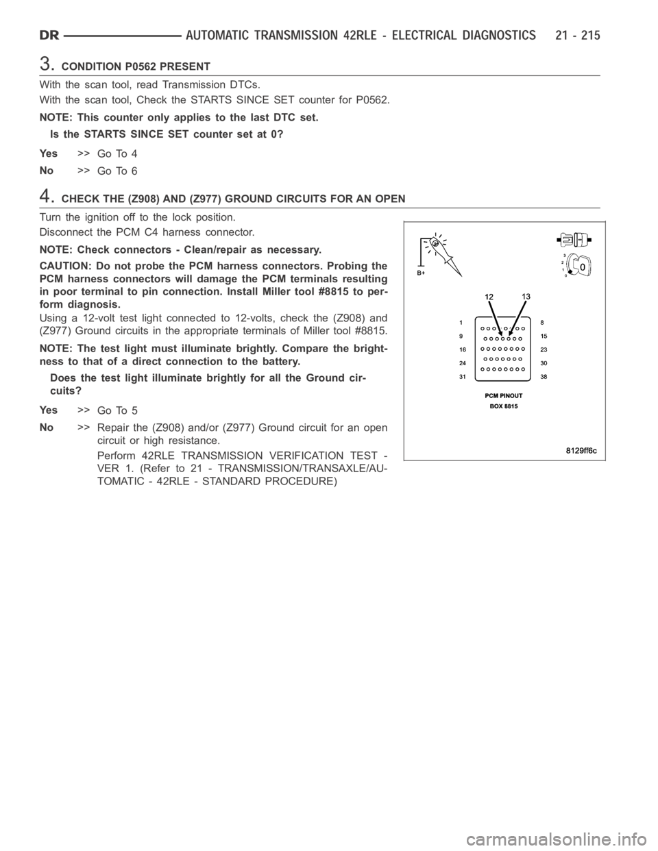
4.CHECK THE (Z908) AND (Z977) GROUND CIRCUITS FOR AN OPEN
Turn the ignition off to the lock position.
Disconnect the PCM C4 harness connector.
NOTE: Check connectors - Clean/repair as necessary.
CAUTION: Do not probe the PCM harness connectors. Probing the
PCM harness connectors will damage the PCM terminals resulting
in poor terminal to pin connection. Install Miller tool #8815 to per-
form diagnosis.
Using a 12-volt test light connected to 12-volts, check the (Z908) and
(Z977) Ground circuits in the appropriate terminals of Miller tool #8815.
NOTE: The test light must illuminate brightly. Compare the bright-
ness to that of a direct connection to the battery.
Does the test light illuminate brightly for all the Ground cir-
cuits?
Ye s>>
Go To 5
No>>
Repair the (Z908) and/or (Z977) Ground circuit for an open
circuit or high resistance.
Perform 42RLE TRANSMISSION VERIFICATION TEST -
VER 1. (Refer to 21 - TRANSMISSION/TRANSAXLE/AU-
TOMATIC - 42RLE - STANDARD PROCEDURE)