2006 DODGE RAM SRT-10 battery
[x] Cancel search: batteryPage 2809 of 5267
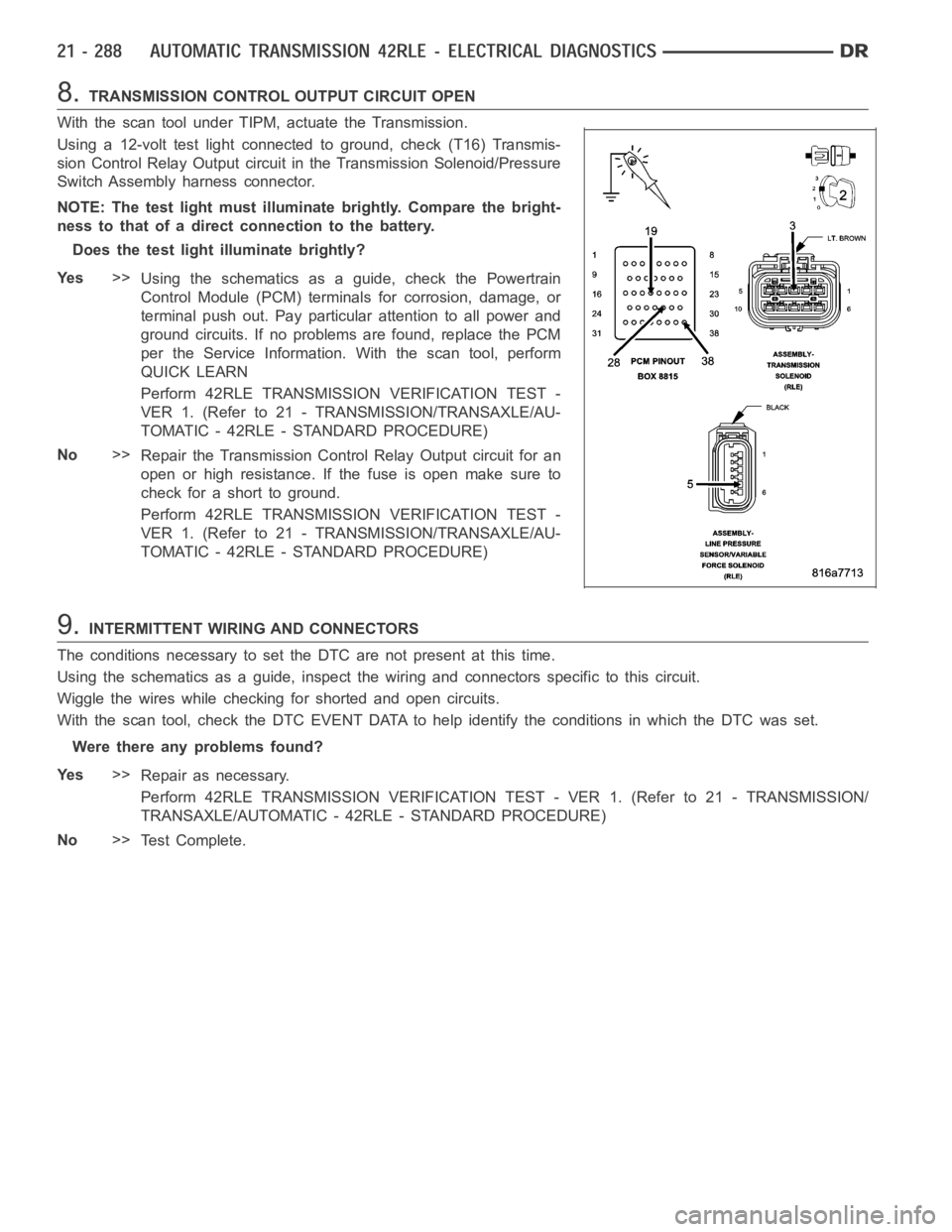
8.TRANSMISSION CONTROL OUTPUT CIRCUIT OPEN
With the scan tool under TIPM, actuate the Transmission.
Using a 12-volt test light connected to ground, check (T16) Transmis-
sion Control Relay Output circuit in the Transmission Solenoid/Pressure
Switch Assembly harness connector.
NOTE: The test light must illuminate brightly. Compare the bright-
ness to that of a direct connection to the battery.
Does the test light illuminate brightly?
Ye s>>
Using the schematics as a guide, check the Powertrain
Control Module (PCM) terminals for corrosion, damage, or
terminal push out. Pay particular attention to all power and
ground circuits. If no problems are found, replace the PCM
per the Service Information.With the scan tool, perform
QUICK LEARN
Perform 42RLE TRANSMISSION VERIFICATION TEST -
VER 1. (Refer to 21 - TRANSMISSION/TRANSAXLE/AU-
TOMATIC - 42RLE - STANDARD PROCEDURE)
No>>
Repair the Transmission Control Relay Output circuit for an
open or high resistance. If the fuse is open make sure to
check for a short to ground.
Perform 42RLE TRANSMISSION VERIFICATION TEST -
VER 1. (Refer to 21 - TRANSMISSION/TRANSAXLE/AU-
TOMATIC - 42RLE - STANDARD PROCEDURE)
9.INTERMITTENT WIRING AND CONNECTORS
The conditions necessary to set the DTC are not present at this time.
Using the schematics as a guide, inspect the wiring and connectors specifictothiscircuit.
Wiggle the wires while checking for shorted and open circuits.
With the scan tool, check the DTC EVENT DATA to help identify the conditionsin which the DTC was set.
Were there any problems found?
Ye s>>
Repair as necessary.
Perform 42RLE TRANSMISSION VERIFICATION TEST - VER 1. (Refer to 21 - TRANSMISSION/
TRANSAXLE/AUTOMATIC - 42RLE - STANDARD PROCEDURE)
No>>
Te s t C o m p l e t e .
Page 2831 of 5267
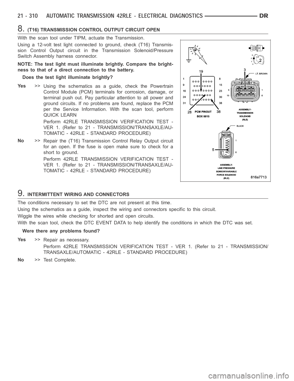
8.(T16) TRANSMISSION CONTROL OUTPUT CIRCUIT OPEN
With the scan tool under TIPM, actuate the Transmission.
Using a 12-volt test light connected to ground, check (T16) Transmis-
sion Control Output circuit in the Transmission Solenoid/Pressure
Switch Assembly harness connector.
NOTE: The test light must illuminate brightly. Compare the bright-
ness to that of a direct connection to the battery.
Does the test light illuminate brightly?
Ye s>>
Using the schematics as a guide, check the Powertrain
Control Module (PCM) terminals for corrosion, damage, or
terminal push out. Pay particular attention to all power and
ground circuits. If no problems are found, replace the PCM
per the Service Information.With the scan tool, perform
QUICK LEARN
Perform 42RLE TRANSMISSION VERIFICATION TEST -
VER 1. (Refer to 21 - TRANSMISSION/TRANSAXLE/AU-
TOMATIC - 42RLE - STANDARD PROCEDURE)
No>>
Repair the (T16) Transmission Control Relay Output circuit
for an open. If the fuse is open make sure to check for a
short to ground.
Perform 42RLE TRANSMISSION VERIFICATION TEST -
VER 1. (Refer to 21 - TRANSMISSION/TRANSAXLE/AU-
TOMATIC - 42RLE - STANDARD PROCEDURE)
9.INTERMITTENT WIRING AND CONNECTORS
The conditions necessary to set the DTC are not present at this time.
Using the schematics as a guide, inspect the wiring and connectors specifictothiscircuit.
Wiggle the wires while checking for shorted and open circuits.
With the scan tool, check the DTC EVENT DATA to help identify the conditionsin which the DTC was set.
Were there any problems found?
Ye s>>
Repair as necessary.
Perform 42RLE TRANSMISSION VERIFICATION TEST - VER 1. (Refer to 21 - TRANSMISSION/
TRANSAXLE/AUTOMATIC - 42RLE - STANDARD PROCEDURE)
No>>
Te s t C o m p l e t e .
Page 2846 of 5267

P0890-SWITCHED BATTERY
For a complete wiring diagramRefer to Section 8W.
Page 2847 of 5267
When Monitored:
One time after a reset (ignition key turned to the RUN position or after cranking engine).
Set Condition:
A fault is set if voltage greater than 4.5 volts is detected for 7 msec on any of the pressure switch circuits
before the relay is energized. The transmission is placed in Limp-In. The MIL is on after 10 seconds. of vehicle
operation.
Possible Causes
(T47) 2/4 PRESSURE SWITCH SENSE CIRCUIT SHORT TO VOLTAGE
(T50) L/R PRESSURE SWITCH SENSE CIRCUIT SHORT TO VOLTAGE
(T9) OD PRESSURE SWITCH SENSE CIRCUIT SHORT TO VOLTAGE
POWERTRAIN CONTROL MODULE
Always perform the 42RLE Pre-Diagnostic Troubleshooting procedure before proceeding. (Refer to 21 -
TRANSMISSION/TRANSAXLE/AUTOMATIC - 42RLE - STANDARD PROCEDURE)
Theory of Operation
The transmission relay is used to supply power to the solenoid pack when in normal operating mode and to turn off
power to produce transmission
limp-inmode. The relay output (which supplies power to the solenoid pack) is fed
back to the controller. It is referred to as SWITCHED BATTERY. After a controller reset (ignition key turned to the
RUN position or after cranking engine), the controller verifies that the relay contacts are open by checking for no
voltage on Switched battery line (transmission control relay output) before the relay is energized. After switched
battery is verified for no voltage, the voltage of each of the solenoid packpressure switches is also checked. Since
the solenoid pack is not powered up, there should be no voltage on any of the pressure switches.
Diagnostic Test
1.CHECK TO SEE IF DTC P0890 IS PRESENT
With the scan tool, view DTCs.
Is the status Active for this DTC or is the STARTS SINCE SET counter set at 0?
Ye s>>
Go To 2
No>>
Go To 5
Page 2850 of 5267
P0897-TRANSMISSION FLUID DETERIORATED
For a complete wiring diagramRefer to Section 8W.
When Monitored:
Each transition from full EMCC to partial EMCC for A/C bump prevention.
Set Condition:
DTC set if 20 occurrences of a turbine acceleration sum. Fault Set Time: 20 transitions from full EMCC to
partial EMCC. Transmission will not use partial EMCC. Established for A/Cbump prevention.
Possible Causes
WORN OUT/ BURNT TRANSAXLE FLUID
Always perform the 42RLE Pre-Diagnostic Troubleshooting procedure before proceeding. (Refer to 21 -
TRANSMISSION/TRANSAXLE/AUTOMATIC - 42RLE - STANDARD PROCEDURE)
Theory of Operation
To prevent a bump due to A/C clutch engagement, a temporary torque converter partial EMCC condition is estab-
lished prior to A/C clutch engagement. A message is received over the bus indicating that A/C clutch engagement
is imminent. Partial EMCC is then established and a reply message,
OK to engage A/C clutchis sent via the bus.
Partial EMCC will be held for 450 ms before returning to full EMCC. During the transition from full to partial EMCC,
a turbine acceleration sum is calculated, if this value exceeds a threshold value for several transitions, degraded
transmission fluid is indicated.
Diagnostic Test
1.WORN OUT/ BURNT TRANSMISSION FLUID
Turn the ignition off to the lock position.
Flush the Transmission Oil Cooler and lines, replace the Transmission OilFilter, refill with new Transmission Fluid,
start the engine, and adjust the fluid per the Service Information.
NOTE: The Transmission Cooler must be flushed before proceeding.
Allow the engine to idle for 10 minutes, in Park.
Turn the ignition off to the lock position.
Again, flush the Transmission Oil Cooler and lines, replace the Transmission Oil Filter, refill with new Transmission
Fluid, start the engine, and adjust the fluid per the Service Information.
With the scan tool, perform a Battery Disconnect.
NOTE: The Battery Disconnect must be done to re-enable EMCC during an A/C Clutch engagement.
NOTE: The vehicle may exhibit intermittent shudder during the first few hundred miles. The new Transmis-
sion Fluid will gradually penetrate the Torque Convertor Clutch frictionmaterial and the shudder should
disappear.
Erase the DTC and return the vehicle to the customer.
Did the DTC reset and/or does the vehicle still shudder after a few thousandmiles?
Ye s>>
Replace the Torque Converter per the Service Information.
Perform 42RLE TRANSMISSION VERIFICATION TEST - VER 1. (Refer to 21 - TRANSMISSION/
TRANSAXLE/AUTOMATIC - 42RLE - STANDARD PROCEDURE)
No>>
Te s t C o m p l e t e .
Page 2868 of 5267
When Monitored:
With the ignition on. Battery voltage greater than 10 volts.
Set Condition:
A shorted condition is detected in the Transmission Control Output circuit.
Possible Causes
(T16) TRANSMISSION CONTROL OUTPUT CIRCUIT SHORT TO GROUND
(T16) TRANSMISSION CONTROL OUTPUT CIRCUIT FOR AN OPEN
TOTALLY INTEGRATED POWER MODULE (TIPM)
Diagnostic Test
1.CHECK IF THE DTC IS ACTIVE
Ignition on, engine not running.
With the scan tool, check TIPM DTCs.
Is the status Active for this DTC?
Ye s>>
Go to 2
No>>
Go to 5
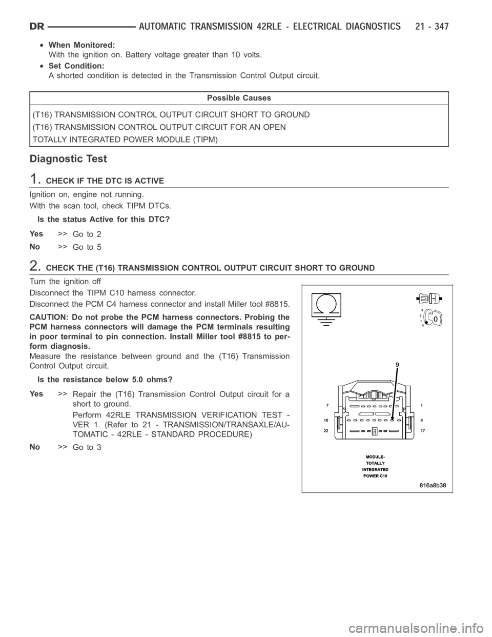
2.CHECK THE (T16) TRANSMISSION CONTROL OUTPUT CIRCUIT SHORT TO GROUND
Turn the ignition off
Disconnect the TIPM C10 harness connector.
Disconnect the PCM C4 harness connector and install Miller tool #8815.
CAUTION: Do not probe the PCM harness connectors. Probing the
PCM harness connectors will damage the PCM terminals resulting
in poor terminal to pin connection. Install Miller tool #8815 to per-
form diagnosis.
Measure the resistance between ground and the (T16) Transmission
Control Output circuit.
Is the resistance below 5.0 ohms?
Ye s>>
Repair the (T16) Transmission Control Output circuit for a
short to ground.
Perform 42RLE TRANSMISSION VERIFICATION TEST -
VER 1. (Refer to 21 - TRANSMISSION/TRANSAXLE/AU-
TOMATIC - 42RLE - STANDARD PROCEDURE)
No>>
Go to 3
Page 2869 of 5267
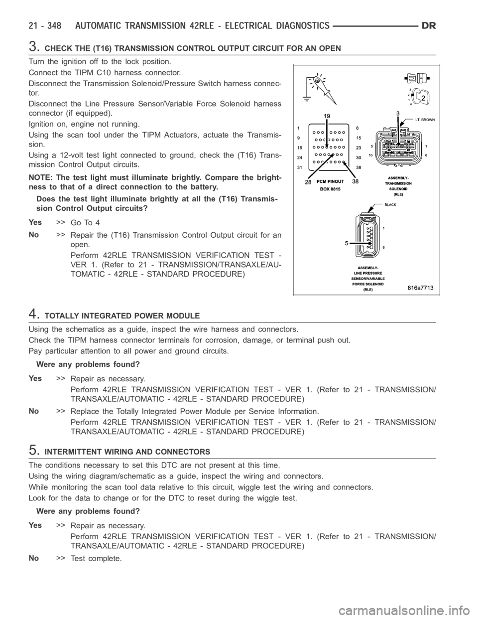
3.CHECK THE (T16) TRANSMISSION CONTROL OUTPUT CIRCUIT FOR AN OPEN
Turn the ignition off to the lock position.
Connect the TIPM C10 harness connector.
Disconnect the Transmission Solenoid/Pressure Switch harness connec-
tor.
Disconnect the Line Pressure Sensor/Variable Force Solenoid harness
connector (if equipped).
Ignition on, engine not running.
Using the scan tool under the TIPM Actuators, actuate the Transmis-
sion.
Using a 12-volt test light connected to ground, check the (T16) Trans-
mission Control Output circuits.
NOTE: The test light must illuminate brightly. Compare the bright-
ness to that of a direct connection to the battery.
Does the test light illuminate brightly at all the (T16) Transmis-
sion Control Output circuits?
Ye s>>
Go To 4
No>>
Repair the (T16) Transmission Control Output circuit for an
open.
Perform 42RLE TRANSMISSION VERIFICATION TEST -
VER 1. (Refer to 21 - TRANSMISSION/TRANSAXLE/AU-
TOMATIC - 42RLE - STANDARD PROCEDURE)
4.TOTALLY INTEGRATED POWER MODULE
Using the schematics as a guide, inspect the wire harness and connectors.
Check the TIPM harness connector terminals for corrosion, damage, or terminal push out.
Pay particular attention to all power and ground circuits.
Were any problems found?
Ye s>>
Repair as necessary.
Perform 42RLE TRANSMISSION VERIFICATION TEST - VER 1. (Refer to 21 - TRANSMISSION/
TRANSAXLE/AUTOMATIC - 42RLE - STANDARD PROCEDURE)
No>>
Replace the Totally Integrated Power Module per Service Information.
Perform 42RLE TRANSMISSION VERIFICATION TEST - VER 1. (Refer to 21 - TRANSMISSION/
TRANSAXLE/AUTOMATIC - 42RLE - STANDARD PROCEDURE)
5.INTERMITTENT WIRING AND CONNECTORS
The conditions necessary to set this DTC are not present at this time.
Using the wiring diagram/schematic as a guide, inspect the wiring and connectors.
While monitoring the scan tool data relative to this circuit, wiggle test the wiring and connectors.
Look for the data to change or for the DTC to reset during the wiggle test.
Were any problems found?
Ye s>>
Repair as necessary.
Perform 42RLE TRANSMISSION VERIFICATION TEST - VER 1. (Refer to 21 - TRANSMISSION/
TRANSAXLE/AUTOMATIC - 42RLE - STANDARD PROCEDURE)
No>>
Te s t c o m p l e t e .
Page 2871 of 5267
When Monitored:
With the ignition on. Battery voltage greater than 10 volts.
Set Condition:
A shorted condition is detected in the TIPM TCM Power control circuit.
Possible Causes
(T16) TRANSMISSION CONTROL OUTPUT CIRCUIT SHORT TO VOLTAGE
TOTALLY INTEGRATED POWER MODULE (TIPM)
Diagnostic Test
1.CHECK IF THE DTC IS ACTIVE
Ignition on, engine not running.
With the scan tool, read TIPM DTCs.
Is the status Active for this DTC?
Ye s>>
Go to 2
No>>
Go to 4
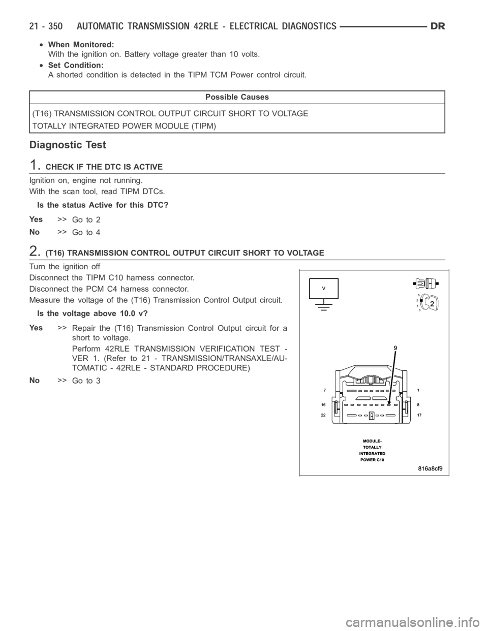
2.(T16) TRANSMISSION CONTROL OUTPUT CIRCUIT SHORT TO VOLTAGE
Turn the ignition off
Disconnect the TIPM C10 harness connector.
Disconnect the PCM C4 harness connector.
Measure the voltage of the (T16) Transmission Control Output circuit.
Is the voltage above 10.0 v?
Ye s>>
Repair the (T16) Transmission Control Output circuit for a
short to voltage.
Perform 42RLE TRANSMISSION VERIFICATION TEST -
VER 1. (Refer to 21 - TRANSMISSION/TRANSAXLE/AU-
TOMATIC - 42RLE - STANDARD PROCEDURE)
No>>
Go to 3