Page 2438 of 5267
INSTALLATION
1. Install the upper steering coupling shaft (3) to the
vehicle.
2. Install the upper steering coupling shaft seal (2) by
pushing it in securing the four tangs (1) to the
panel.
NOTE: A new steering coupling shaft pinch bolt
for the upper and lower shafts must be used.
3. Install the steering coupler shaft (1) to the column.
4. Install the upper pinch bolt (3) use new bolt and
tighten to 57 N.m (42 ft.lbs).
5. Install the shaft to the lower coupler (1).
6. Install the lower pinch bolt (1) use new bolt and
tighten to 57 N.m (42 ft.lbs).
7. Unlock the steering wheel.
8. Reconnect the negative battery cable.
Page 2439 of 5267

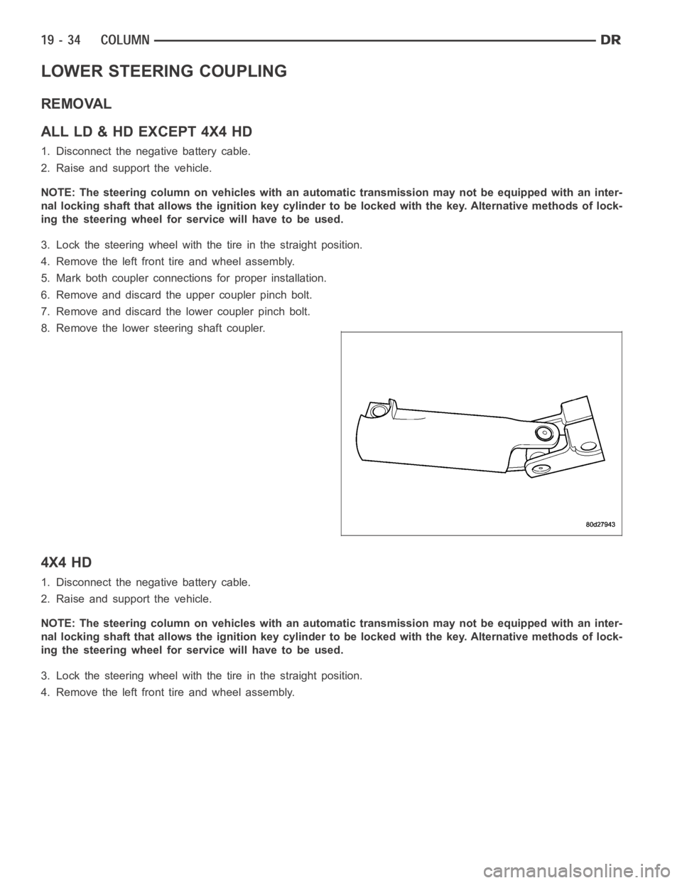
LOWER STEERING COUPLING
REMOVAL
ALLLD&HDEXCEPT4X4HD
1. Disconnect the negative battery cable.
2. Raise and support the vehicle.
NOTE: The steering column on vehicles with an automatic transmission may not be equipped with an inter-
nal locking shaft that allows the ignition key cylinder to be locked with the key. Alternative methods of lock-
ing the steering wheel for service will have to be used.
3. Lock the steering wheel with the tire in the straight position.
4. Remove the left front tire and wheel assembly.
5. Mark both coupler connections for proper installation.
6. Remove and discard the upper coupler pinch bolt.
7. Remove and discard the lower coupler pinch bolt.
8. Remove the lower steering shaft coupler.
4X4 HD
1. Disconnect the negative battery cable.
2. Raise and support the vehicle.
NOTE: The steering column on vehicles with an automatic transmission may not be equipped with an inter-
nal locking shaft that allows the ignition key cylinder to be locked with the key. Alternative methods of lock-
ing the steering wheel for service will have to be used.
3. Lock the steering wheel with the tire in the straight position.
4. Remove the left front tire and wheel assembly.
Page 2441 of 5267
INSTALLATION
ALLLD&HDEXCEPT4X4HD
1. Install the coupler to the steering rack & pinion
using the marks made in the removal process.
2. Install the coupler to the intermediate shaft using
the marks made in the removal process.
NOTE: New pinch bolts must be used for reinstal-
lation.
3. Install the lower pinch bolt and tighten to 57 Nꞏm
(42 ft. lbs.).SRT10. Tighten to 38 Nꞏm (28 ft.
lbs.).
4. Install the upper pinch bolt and tighten to 57 Nꞏm
(42 ft. lbs.).
5. Install the left front tire and wheel assembly (Refer to 22 - TIRES/WHEELS/WHEELS - STANDARD PROCE-
DURE).
6. Lower the vehicle.
7. Reconnect the negative battery cable.
8. Unlock the steering wheel.
4X4 HD
1. Install the coupler (2) to the steering gear (3).
Page 2442 of 5267
2. Install the coupler (3) to the intermediate shaft (2).
NOTE: New pinch bolts must be used for reinstal-
lation.
3. Install the lower pinch bolt (3) and tighten to 28
Nꞏm (250 in. lbs.).
4. Install the upper pinch bolt (1) and tighten to 57
Nꞏm (42 ft. lbs.).
5. Install the left front tire and wheel assembly (Refer to 22 - TIRES/WHEELS/WHEELS - STANDARD PROCE-
DURE).
6. Lower the vehicle.
7. Reconnect the negative battery cable.
8. Unlock the steering wheel.
Page 2502 of 5267

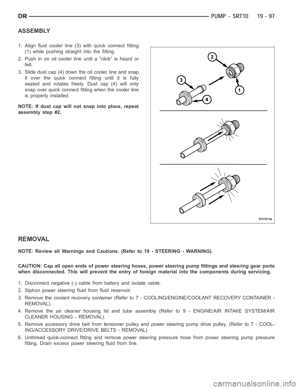
ASSEMBLY
1. Align fluid cooler line (3) with quick connect fitting
(1) while pushing straight into the fitting.
2. Push in on oil cooler line until a “click” is heard or
felt.
3. Slide dust cap (4) down the oil cooler line and snap
it over the quick connect fitting until it is fully
seated and rotates freely. Dust cap (4) will only
snap over quick connect fitting when the cooler line
is properly installed.
NOTE: If dust cap will not snap into place, repeat
assembly step #2.
REMOVAL
NOTE: Review all Warnings and Cautions. (Refer to 19 - STEERING - WARNING).
CAUTION: Cap all open ends of power steering hoses, power steering pump fittings and steering gear ports
when disconnected. This will prevent the entry of foreign material into the components during servicing.
1. Disconnect negative (-) cable from battery and isolate cable.
2. Siphon power steering fluid from fluid reservoir.
3. Remove the coolant recovery container (Refer to 7 - COOLING/ENGINE/COOLANT RECOVERY CONTAINER -
REMOVAL).
4. Remove the air cleaner housing lid and tube assembly (Refer to 9 - ENGINE/AIR INTAKE SYSTEM/AIR
CLEANER HOUSING - REMOVAL).
5. Remove accessory drive belt from tensioner pulley and power steering pump drive pulley. (Refer to 7 - COOL-
ING/ACCESSORY DRIVE/DRIVE BELTS - REMOVAL)
6. Unthread quick-connect fitting and remove power steering pressure hose from power steering pump pressure
fitting. Drain excess power steering fluid from line.
Page 2504 of 5267

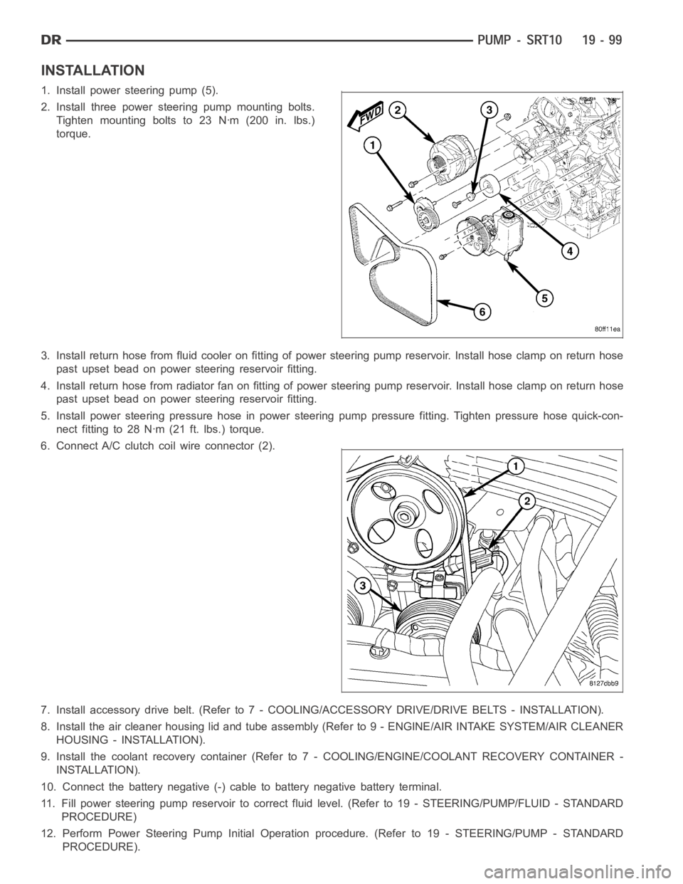
INSTALLATION
1. Install power steering pump (5).
2. Install three power steering pump mounting bolts.
Tighten mounting bolts to 23 Nꞏm (200 in. lbs.)
torque.
3. Install return hose from fluid cooler on fitting of power steering pump reservoir. Install hose clamp on return hose
past upset bead on power steering reservoir fitting.
4. Install return hose from radiator fan on fitting of power steering pump reservoir. Install hose clamp on return hose
past upset bead on power steering reservoir fitting.
5. Install power steering pressure hose in power steering pump pressure fitting. Tighten pressure hose quick-con-
nect fitting to 28 Nꞏm (21 ft. lbs.) torque.
6. Connect A/C clutch coil wire connector (2).
7. Install accessory drive belt. (Refer to 7 - COOLING/ACCESSORY DRIVE/DRIVE BELTS - INSTALLATION).
8. Install the air cleaner housing lid and tube assembly (Refer to 9 - ENGINE/AIR INTAKE SYSTEM/AIR CLEANER
HOUSING - INSTALLATION).
9. Install the coolant recovery container (Refer to 7 - COOLING/ENGINE/COOLANT RECOVERY CONTAINER -
INSTALLATION).
10. Connect the battery negative (-) cable to battery negative battery terminal.
11. Fill power steering pump reservoir to correct fluid level. (Refer to 19- STEERING/PUMP/FLUID - STANDARD
PROCEDURE)
12. Perform Power Steering Pump Initial Operation procedure. (Refer to 19- STEERING/PUMP - STANDARD
PROCEDURE).
Page 2525 of 5267
REMOVAL
1. With vehicle in neutral, position vehicle on hoist.
2. Disconnect battery negative cable.
3. Remove shift boot bezel screws and slide boot
upward on shift lever extension.
4. Remove shift lever extension from the shift tower
and lever assembly.
5. Remove 4WD shift boot if equipped.
6. Remove skid plate, if equipped.
7. Remove drain plug (1) from transmission (2) and
drain fluid.
8. Mark transmission flange (1) and propeller shaft (2)
for installation reference before removing propeller
shaft. If 4x4 equipped mark transfer case and front
propeller shaft before removing shaft.
Page 2583 of 5267

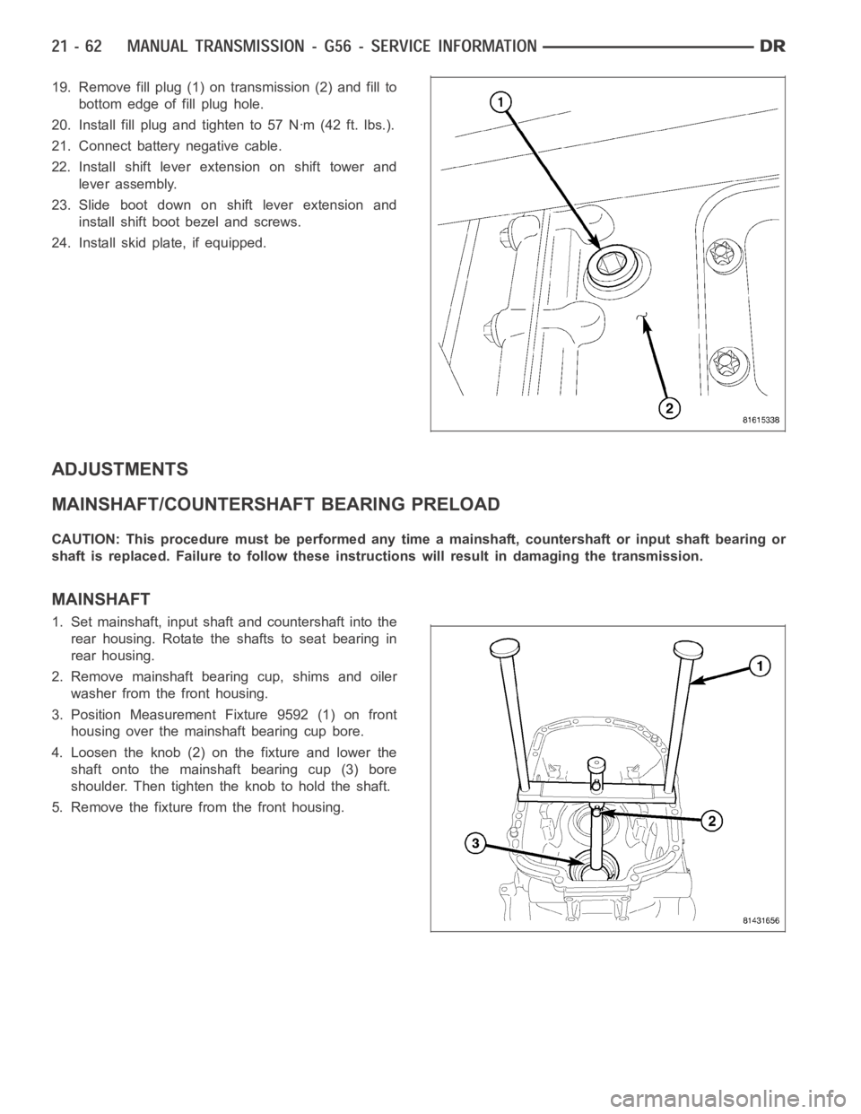
19. Remove fill plug (1) on transmission (2) and fill to
bottom edge of fill plug hole.
20. Install fill plug and tighten to 57 Nꞏm (42 ft. lbs.).
21. Connect battery negative cable.
22. Install shift lever extension on shift tower and
lever assembly.
23. Slide boot down on shift lever extension and
install shift boot bezel and screws.
24. Install skid plate, if equipped.
ADJUSTMENTS
MAINSHAFT/COUNTERSHAFT BEARING PRELOAD
CAUTION: This procedure must be performed any time a mainshaft, countershaft or input shaft bearing or
shaft is replaced. Failure to follow these instructions will result in damaging the transmission.
MAINSHAFT
1. Set mainshaft, input shaft and countershaft into the
rear housing. Rotate the shafts to seat bearing in
rear housing.
2. Remove mainshaft bearing cup, shims and oiler
washer from the front housing.
3. Position Measurement Fixture 9592 (1) on front
housing over the mainshaft bearing cup bore.
4. Loosen the knob (2) on the fixture and lower the
shaft onto the mainshaft bearing cup (3) bore
shoulder. Then tighten the knob to hold the shaft.
5. Remove the fixture from the front housing.