Page 2269 of 5267

5.7L
1. If fuel injectors are to be installed, (Refer to 14 -
FUEL SYSTEM/FUEL INJECTION/FUEL INJEC-
TOR - INSTALLATION).
2. Clean out fuel injector machined bores in intake
manifold.
3. Apply a small amount of engine oil to each fuel
injector O-ring. This will helpin fuel rail installation.
4. Position fuel rail/fuel injector assembly to machined
injector openings in intake manifold.
5. Guide each injector into intake manifold. Be careful
not to tear injector O-rings.
6. Pushrightside of fuel rail down until fuel injectors
have bottomed on shoulders. Pushleftfuel rail
down until injectors have bottomed on shoulders.
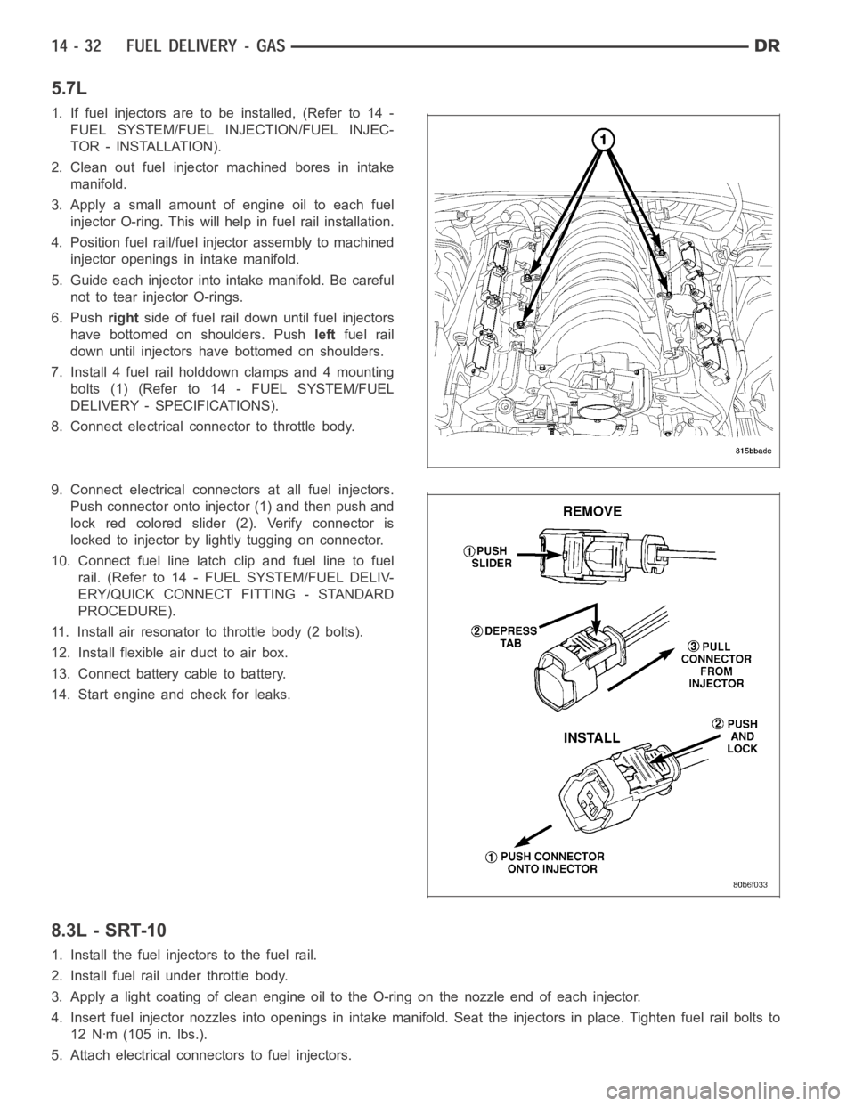
7. Install 4 fuel rail holddown clamps and 4 mounting
bolts (1) (Refer to 14 - FUEL SYSTEM/FUEL
DELIVERY - SPECIFICATIONS).
8. Connect electrical connector to throttle body.
9. Connect electrical connectors at all fuel injectors.
Push connector onto injector (1) and then push and
lock red colored slider (2). Verify connector is
locked to injector by lightly tugging on connector.
10. Connect fuel line latch clip and fuel line to fuel
rail. (Refer to 14 - FUEL SYSTEM/FUEL DELIV-
ERY/QUICK CONNECT FITTING - STANDARD
PROCEDURE).
11. Install air resonator to throttle body (2 bolts).
12. Install flexible air duct to air box.
13. Connect battery cable to battery.
14. Start engine and check for leaks.
8.3L - SRT-10
1. Install the fuel injectors to the fuel rail.
2. Install fuel rail under throttle body.
3. Apply a light coating of clean engine oiltotheO-ringonthenozzleendofeach injector.
4. Insert fuel injector nozzles into openings in intake manifold. Seat theinjectors in place. Tighten fuel rail bolts to
12 Nꞏm (105 in. lbs.).
5. Attach electrical connectors to fuel injectors.
Page 2270 of 5267
6. Connect the electrical connector to the MAP sensor and Coolant Temperature sensor.
7. Connect the electrical connector to the TPS and Idle Air Control.
8. Install the wiring harness to the wiring clips under the throttle body.
9. Connect fuel supply tube to fuel rail. Refer to Quick Connect Fittings inthe Fuel Delivery section.
10. Install the negative battery cable.
11. Install the air cleaner assembly, refer to the Engine/Air Intake System/Air Cleaner Housing for more information.
12. Use the DRBIII
scan tool ASD Fuel System Test to pressurize the fuel system. Check for leaks.
Page 2293 of 5267

INJECTOR - FUEL
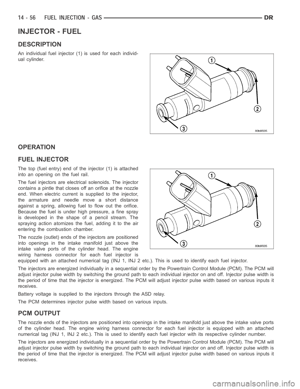
DESCRIPTION
An individual fuel injector (1) is used for each individ-
ual cylinder.
OPERATION
FUEL INJECTOR
The top (fuel entry) end of the injector (1) is attached
into an opening on the fuel rail.
The fuel injectors are electrical solenoids. The injector
contains a pintle that closes off an orifice at the nozzle
end. When electric current is supplied to the injector,
the armature and needle move a short distance
against a spring, allowing fuel to flow out the orifice.
Because the fuel is under high pressure, a fine spray
is developed in the shape of a pencil stream. The
spraying action atomizes the fuel, adding it to the air
entering the combustion chamber.
The nozzle (outlet) ends of the injectors are positioned
into openings in the intake manifold just above the
intake valve ports of the cylinder head. The engine
wiring harness connector for each fuel injector is
equipped with an attached numerical tag (INJ 1, INJ 2 etc.). This is used to identify each fuel injector.
The injectors are energized individually in a sequential order by the Powertrain Control Module (PCM). The PCM will
adjust injector pulse width by switching the ground path to each individual injector on and off. Injector pulse width is
the period of time that the injector isenergized. The PCM will adjust injector pulse width based on various inputs it
receives.
Battery voltage is supplied to the injectors through the ASD relay.
The PCM determines injector pulse width based on various inputs.
PCM OUTPUT
The nozzle ends of the injectors are positioned into openings in the intakemanifold just above the intake valve ports
of the cylinder head. The engine wiring harness connector for each fuel injector is equipped with an attached
numerical tag (INJ 1, INJ 2 etc.). This is used to identify each fuel injector with its respective cylinder number.
The injectors are energized individually in a sequential order by the Powertrain Control Module (PCM). The PCM will
adjust injector pulse width by switching the ground path to each individual injector on and off. Injector pulse width is
the period of time that the injector isenergized. The PCM will adjust injector pulse width based on various inputs it
receives.
Page 2294 of 5267
Battery voltage (12 volts +) is supplied to the injectors through the ASD relay. The ASD relay will shut-down the 12
volt power source to the fuel injectors if the PCM senses the ignition is on,but the engine is not running. This
occurs after the engine has not been running for approximately 1.8 seconds.
The PCM determines injector on-time (pulse width) based on various inputs.
REMOVAL
3.7/4.7/ 5.7L
1. Remove fuel rail. (Refer to 14 - FUEL SYSTEM/
FUEL DELIVERY/FUEL RAIL - REMOVAL)
2. Disconnect clip(s) that retain fuel injector(s) to fuel
rail (2).
8.3L - SRT-10
1. Release fuel system pressure. Refer to Fuel Pres-
sure Release Procedure in this section.
2. Remove the battery cover and disconnect negative
battery cable.
3. Remove the air cleaner assembly, refer to the
Engine/Air Intake System/Air Cleaner Housing for
more information.
4. Disconnect the electrical connector to the MAP
sensor and Coolant Temperature sensor.
Page 2297 of 5267

12. Remove the fuel injector from the fuel rail.
INSTALLATION
3.7/ 4.7/ 5.7L
1. Install fuel injector(s) into fuel rail assembly and install retainingclip(s).
2. If same injector(s) is being reinstalled, install new O-ring(s).
3. Apply a small amount of clean engine oil to each injector O-ring. This will aid in installation.
4. Install fuel rail. (Refer to 14 - FUEL SYSTEM/FUEL DELIVERY/FUEL RAIL - INSTALLATION)
5. Start engine and check for fuel leaks.
8.3L - SRT-10
1. Install the fuel injectors to the fuel rail.
2. Install fuel rail under throttle body.
3. Apply a light coating of clean engine oiltotheO-ringonthenozzleendofeach injector.
4. Insert fuel injector nozzles into openings in intake manifold. Seat theinjectors in place. Tighten fuel rail bolts to
12 Nꞏm (105 in. lbs.).
5. Attach electrical connectors to fuel injectors.
6. Connect the electrical connector to the MAP sensor and Coolant Temperature sensor.
7. Connect the electrical connector to the TPS and Idle Air Control.
8. Install the wiring harness to the wiring clips under the throttle body.
9. Connect fuel supply tube to fuel rail. Refer to Quick Connect Fittings inthe Fuel Delivery section
10. Install the negative battery cable and install the battery cover.
11. Install the air cleaner assembly, refer to the Engine/Air Intake System/Air Cleaner Housing for more information.
12. Use the DRBIII
scan tool ASD Fuel System Test to pressurize the fuel system. Check for leaks.
Page 2298 of 5267

RELAY - FUEL PUMP
DESCRIPTION
The 5–pin, 12–volt, fuel pump relay is located in the Power Distribution Center (PDC). Refer to the label on the PDC
cover for relay location.
OPERATION
The Powertrain Control Module (PCM) energizes the electric fuel pump through the fuel pump relay. The fuel pump
relay is energized by first applying battery voltage to it when the ignition key is turned ON, and then applying a
ground signal to the relay from the PCM.
Whenever the ignition key is turned ON, the electric fuel pump will operate. But, the PCM will shut-down the ground
circuit to the fuel pump relay in approximately 1–3 seconds unless the engine is operating or the starter motor is
engaged.
REMOVAL
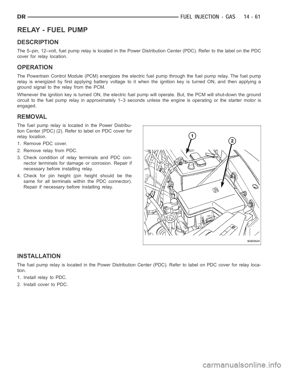
The fuel pump relay is located in the Power Distribu-
tion Center (PDC) (2). Refer to label on PDC cover for
relay location.
1. Remove PDC cover.
2. Remove relay from PDC.
3. Check condition of relay terminals and PDC con-
nector terminals for damage or corrosion. Repair if
necessary before installing relay.
4. Check for pin height (pin height should be the
same for all terminals within the PDC connector).
Repair if necessary before installing relay.
INSTALLATION
The fuel pump relay is located in the Power Distribution Center (PDC). Refer to label on PDC cover for relay loca-
tion.
1. Install relay to PDC.
2. Install cover to PDC.
Page 2305 of 5267
SENSOR - INLET AIR TEMPERATURE
REMOVAL — 8.3L
NOTE: Take care not to damage the thermister pill
when removing the sensor.
1. Remove the battery cover and disconnect the neg-
ative battery cable.
2. Disconnect the electrical connector from the inlet
temperature sensor.
3. Remove sensor from inlet hose.
INSTALLATION
NOTE: Take care not to damage the open ther-
mister pill when installing the sensor.
1. Install sensor , use a little water to aid in insertion
of sensor.
2. Make sure that the rib on the sensor matches up
with the rib on the inlet hose. The thermister pill
shouldbeindirectcontactwiththeinletairstream.
3. Connect the electrical connector.
4. Connect the negative battery cable and install bat-
tery cover.
Page 2326 of 5267
1. Remove air duct and air resonator box at throttle
body.
2. Disconnect electrical connector (2) at throttle body.
3. Remove 4 throttle body mounting bolts (4).
4. Remove throttle body from intake manifold.
5. Check condition of throttle body O-ring (2).
6. If the throttle body has been changed, the following
procedure must be performed:
a. Disconnect negative battery cable from battery.
Leave cable disconnected for approximately 90
seconds.
b. Reconnect cable to battery.
c. Turn ignition switch ON, but do not crank
engine.
d. Leave ignition switch ON for a minimum of 10
seconds. This will allow PCM to learn throttle
body electrical parameters.