Page 2155 of 5267
5.9L DIESEL ENGINE
1. Disconnect the battery negative cables.
2. Raise and support the vehicle.
3. Remove the muffler to tail pipe and extension pipe
clamps.
4. Disconnect the muffler from the hanger isolators.
5. Disconnect the muffler from the tailpipe.
6. Disconnect the muffler from the extension pipe and
remove from the vehicle.
INSTALLATION
3.7L/4.7L/5.7L ENGINE
1. Assemble muffler and clamps loosely to permit
proper alignment of all parts.
2. Connect the muffler hangers.
3.Tightentheclampnutsto54Nꞏm(40ft.lbs.)
torque.
4. Check the exhaust system for contact with the
body panels. A minimum of 25 mm (1.0 in.) is
required between the exhaust system components
and body/frame parts. Make the necessary adjust-
ments, if needed.
5. Lower the vehicle.
6. Start the engine and inspect for exhaust leaks.
Repair exhaust leaks as necessary.
Page 2156 of 5267
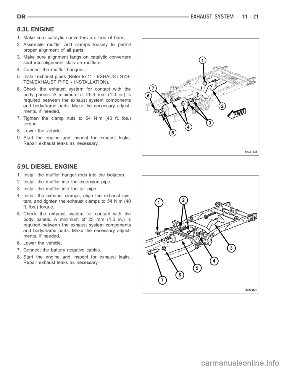
8.3L ENGINE
1. Make sure catalytic converters are free of burrs.
2. Assemble muffler and clamps loosely to permit
proper alignment of all parts.
3. Make sure alignment tangs on catalytic converters
seat into alignment slots on mufflers.
4. Connect the muffler hangers.
5. Install exhaust pipes (Refer to 11 - EXHAUST SYS-
TEM/EXHAUST PIPE - INSTALLATION).
6. Check the exhaust system for contact with the
body panels. A minimum of 25.4 mm (1.0 in.) is
required between the exhaust system components
and body/frame parts. Make the necessary adjust-
ments, if needed.
7.Tightentheclampnutsto54Nꞏm(40ft.lbs.)
torque.
8. Lower the vehicle.
9. Start the engine and inspect for exhaust leaks.
Repair exhaust leaks as necessary.
5.9L DIESEL ENGINE
1. Install the muffler hanger rods into the isolators.
2. Install the muffler into the extension pipe.
3. Install the muffler into the tail pipe.
4. Install the exhaust clamps, align the exhaust sys-
tem, and tighten the exhaust clamps to 54 Nꞏm (40
ft. lbs.) torque.
5. Check the exhaust system for contact with the
body panels. A minimum of 25 mm (1.0 in.) is
required between the exhaust system components
and body/frame parts. Make the necessary adjust-
ments, if needed.
6. Lower the vehicle.
7. Connect the battery negative cables.
8. Start the engine and inspect for exhaust leaks.
Repair exhaust leaks as necessary.
Page 2157 of 5267
TA I L P I P E
REMOVAL
3.7L/4.7L/5.7L ENGINE
1. Raise and support the vehicle.
2. Saturate the clamp nuts with heat valve lubricant.
Allow 5 minutes for penetration.
3. Disconnect the exhaust tailpipe support hanger.
4. Remove clamps and nuts.
5. Remove the exhaust tailpipe.
5.9L DIESEL
1. Disconnect the battery negative cables.
2. Raise and support the vehicle.
3. Saturate the clamp nuts with heat valve lubricant.
Allow 5 minutes for penetration.
4. Disconnect the exhaust tailpipe support hanger iso-
lators.
5. Remove the muffler-to-tailpipe clamps.
6. Remove the tailpipe from the vehicle.
Page 2159 of 5267
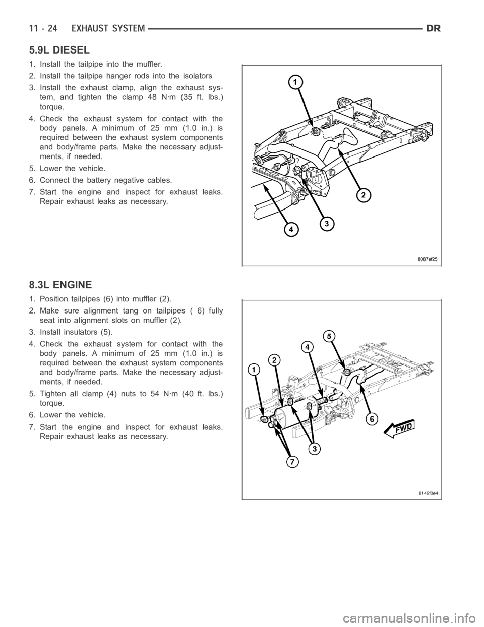
5.9L DIESEL
1. Install the tailpipe into the muffler.
2. Install the tailpipe hanger rods into the isolators
3. Install the exhaust clamp, align the exhaust sys-
tem, and tighten the clamp 48 Nꞏm (35 ft. lbs.)
torque.
4. Check the exhaust system for contact with the
body panels. A minimum of 25 mm (1.0 in.) is
required between the exhaust system components
and body/frame parts. Make the necessary adjust-
ments, if needed.
5. Lower the vehicle.
6. Connect the battery negative cables.
7. Start the engine and inspect for exhaust leaks.
Repair exhaust leaks as necessary.
8.3L ENGINE
1. Position tailpipes (6) into muffler (2).
2. Make sure alignment tang on tailpipes ( 6) fully
seat into alignment slots on muffler (2).
3. Install insulators (5).
4. Check the exhaust system for contact with the
body panels. A minimum of 25 mm (1.0 in.) is
required between the exhaust system components
and body/frame parts. Make the necessary adjust-
ments, if needed.
5. Tighten all clamp (4) nuts to 54 Nꞏm (40 ft. lbs.)
torque.
6. Lower the vehicle.
7. Start the engine and inspect for exhaust leaks.
Repair exhaust leaks as necessary.
Page 2164 of 5267
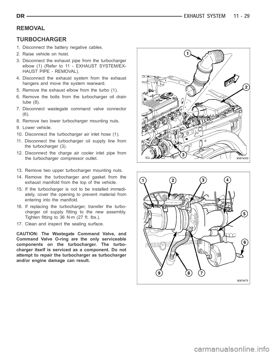
REMOVAL
TURBOCHARGER
1. Disconnect the battery negative cables.
2. Raise vehicle on hoist.
3. Disconnect the exhaust pipe from the turbocharger
elbow (1) (Refer to 11 - EXHAUST SYSTEM/EX-
HAUST PIPE - REMOVAL).
4. Disconnect the exhaust system from the exhaust
hangers and move the system rearward.
5. Remove the exhaust elbow from the turbo (1).
6. Remove the bolts from the turbocharger oil drain
tube (8).
7. Disconnect wastegate command valve connector
(6).
8. Remove two lower turbocharger mounting nuts.
9. Lower vehicle.
10. Disconnect the turbocharger air inlet hose (1).
11. Disconnect the turbocharger oil supply line from
the turbocharger (3).
12. Disconnect the charge air cooler inlet pipe from
the turbocharger compressor outlet.
13. Remove two upper turbocharger mounting nuts.
14. Remove the turbocharger and gasket from the
exhaust manifold from the top of the vehicle.
15. If the turbocharger is not to be installed immedi-
ately, cover the opening to prevent material from
entering into the manifold.
16. If replacing the turbocharger, transfer the turbo-
charger oil supply fitting to the new assembly.
Tighten fitting to 36 Nꞏm (27 ft. lbs.).
17. Clean and inspect the sealing surface.
CAUTION: The Wastegate Command Valve, and
Command Valve O-ring are the only serviceable
components on the turbocharger. The turbo-
charger itself is serviced as a component. Do not
attempt to repair the turbocharger as turbocharger
and/or engine damage can result.
Page 2165 of 5267
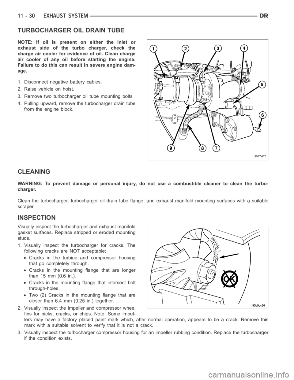
TURBOCHARGER OIL DRAIN TUBE
NOTE: If oil is present on either the inlet or
exhaust side of the turbo charger, check the
charge air cooler for evidence of oil. Clean charge
air cooler of any oil before starting the engine.
Failure to do this can result in severe engine dam-
age.
1. Disconnect negative battery cables.
2. Raise vehicle on hoist.
3. Remove two turbocharger oil tube mounting bolts
4. Pulling upward, remove the turbocharger drain tube
from the engine block.
CLEANING
WARNING: To prevent damage or personal injury, do not use a combustible cleaner to clean the turbo-
charger.
Clean the turbocharger, turbocharger oil drain tube flange, and exhaust manifold mounting surfaces with a suitable
scraper.
INSPECTION
Visually inspect the turbocharger and exhaust manifold
gasket surfaces. Replace stripped or eroded mounting
studs.
1. Visually inspect the turbocharger for cracks. The
following cracks are NOT acceptable:
Cracks in the turbine and compressor housing
that go completely through.
Cracks in the mounting flange that are longer
than 15 mm (0.6 in.).
Cracks in the mounting flange that intersect bolt
through-holes.
Two (2) Cracks in the mounting flange that are
closer than 6.4 mm (0.25 in.) together.
2. Visually inspect the impeller and compressor wheel
fins for nicks, cracks, or chips. Note: Some impel-
lers may have a factory placed paint mark which, after normal operation, appears to be a crack. Remove this
mark with a suitable solvent to verify that it is not a crack.
3. Visually inspect the turbocharger compressor housing for an impeller rubbing condition. Replace the turbocharger
if the condition exists.
Page 2167 of 5267
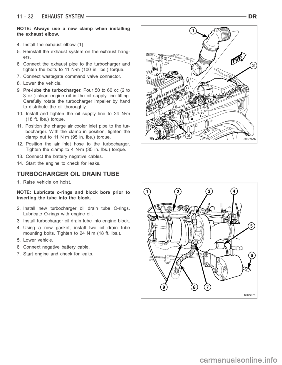
NOTE: Always use a new clamp when installing
the exhaust elbow.
4. Install the exhaust elbow (1)
5. Reinstall the exhaust system on the exhaust hang-
ers.
6. Connect the exhaust pipe to the turbocharger and
tighten the bolts to 11 Nꞏm (100 in. lbs.) torque.
7. Connect wastegate command valve connector.
8. Lower the vehicle.
9.Pre-lube the turbocharger.Pour 50 to 60 cc (2 to
3 oz.) clean engine oil in the oil supply line fitting.
Carefully rotate the turbocharger impeller by hand
to distribute the oil thoroughly.
10. Install and tighten the oil supply line to 24 Nꞏm
(18 ft. lbs.) torque.
11. Position the charge air cooler inlet pipe to the tur-
bocharger. With the clamp in position, tighten the
clamp nut to 11 Nꞏm (95 in. lbs.) torque.
12. Position the air inlet hose to the turbocharger.
Tighten the clamp to 4 Nꞏm (35 in. lbs.) torque.
13. Connect the battery negative cables.
14. Start the engine to check for leaks.
TURBOCHARGER OIL DRAIN TUBE
1. Raise vehicle on hoist.
NOTE: Lubricate o-rings and block bore prior to
inserting the tube into the block.
2. Install new turbocharger oil drain tube O-rings.
Lubricate O-rings with engine oil.
3. Install turbocharger oil drain tube into engine block.
4. Using a new gasket, install two oil drain tube
mounting bolts. Tighten to 24 Nꞏm (18 ft. lbs.).
5. Lower vehicle.
6. Connect negative battery cable.
7. Start engine and check for leaks.
Page 2168 of 5267
WASTEGATE - ELECTRONIC ACTUATOR
REMOVAL
1. Disconnect battery negative cable.
2. Remove air inlet tube.
3. Disconnect wastegate command valve connector.
4. Remove wastegate command valve.
5. Inspect wastegate command valve O-rings for cuts,
nicks, or damage.
6. Inspect valve tip and body for damage or debris.
7. Inspect threads in turbocharger housing for
damage.
INSTALLATION
1. Install new wastegate command valve O-rings onto
the wastegate command valve. Do not lubricate
O-rings.
2. Install wastegate command valve. Tighten to 34
Nꞏm (25 ft. lbs.).
3. Connect wastegate command valve connector.
4. Install air inlet tube.
5. Install negative battery cables.