Page 2078 of 5267

COVER-TIMING CHAIN
REMOVAL
1. Disconnect negative battery cable.
2. Disconnect throttle body air inlet duct at the throttle
body, CCV hose, disconnect the IAT sensor and
remove air cleaner housing cover (Refer to 9 -
ENGINE/AIR INTAKE SYSTEM - REMOVAL).
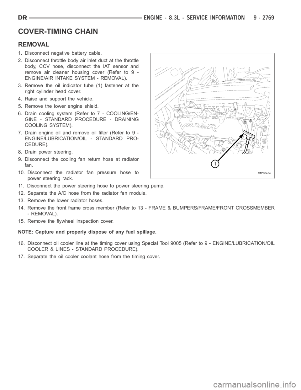
3. Remove the oil indicator tube (1) fastener at the
right cylinder head cover.
4. Raise and support the vehicle.
5. Remove the lower engine shield.
6. Drain cooling system (Refer to 7 - COOLING/EN-
GINE - STANDARD PROCEDURE - DRAINING
COOLING SYSTEM).
7. Drain engine oil and remove oil filter (Refer to 9 -
ENGINE/LUBRICATION/OIL - STANDARD PRO-
CEDURE).
8. Drain power steering.
9. Disconnect the cooling fan return hose at radiator
fan.
10. Disconnect the radiator fan pressure hose to
power steering rack.
11. Disconnect the power steering hose to power steering pump.
12. Separate the A/C hose from the radiator fan module.
13. Remove the lower radiator hoses.
14. Remove the front frame cross member (Refer to 13 - FRAME & BUMPERS/FRAME/FRONT CROSSMEMBER
- REMOVAL).
15. Remove the flywheel inspection cover.
NOTE: Capture and properly dispose of any fuel spillage.
16. Disconnect oil cooler line at the timing cover using Special Tool 9005 (Refer to 9 - ENGINE/LUBRICATION/OIL
COOLER & LINES - STANDARD PROCEDURE).
17. Separate the oil cooler coolant hose from the timing cover.
Page 2082 of 5267
33. Raise and support the vehicle.
34. Connect the hydraulic lines to the fan assembly and steering rack then connect the A/C hose to the fan shroud.
35. Install aNewoil filter.
36. Lower the vehicle.
37. Install upper radiator hose and connect the ground wire at the thermostat housing.
38. Install air cleaner housing cover assembly, connect throttle body airinlet duct, IAT sensor and CCV hose. (Refer
to 9 - ENGINE/AIR INTAKE SYSTEM - INSTALLATION).
39. Fill and purge air from the power steering system.
40. Fill engine crankcase with proper oil to correct level.
41. Fill and purge air from the cooling system (Refer to 7 - COOLING/ENGINE -STANDARD PROCEDURE - FILL-
ING COOLING SYSTEM).
42. Connect negative battery cable.
43. Start the vehicle and inspect for leaks.
44. Install the lower engine shield.
Page 2087 of 5267

INSPECTION FOR REAR SEAL AREA LEAKS
Since it is sometimes difficult to determine the source of an oil leak in therear seal area of the engine, a more
involved inspection is necessary. The following steps should be followedto help pinpoint the source of the leak.
If the leakage occurs at the crankshaft rear oil seal area:
1. Disconnect the battery.
2. Raise the vehicle.
3. Remove torque converter or clutch housing cover and inspect rear of block for evidence of oil. Use a black light
to check for the oil leak:
a. Circular spray pattern generally indicates seal leakage or crankshaftdamage.
b. Where leakage tends to run straight down, possible causes are a porous block, distributor seal, camshaft
bore cup plugs oil galley pipe plugs, oil filter runoff, and main bearing cap to cylinder block mating surfaces.
4. If no leaks are detected, pressurize the crankcase as outlined in the, Inspection (Engine oil Leaks in general)
CAUTION: Do not exceed 20.6 kPa (3 psi).
5. If the leak is not detected, very slowly turn the crankshaft and watch forleakage. If a leak is detected between
the crankshaft and seal while slowly turning the crankshaft, it is possible the crankshaft seal surface is damaged.
The seal area on the crankshaft could have minor nicks or scratches that canbe polished out with emery cloth.
CAUTION: Use extreme caution when crankshaft polishing is necessary to remove minor nicks and
scratches. The crankshaft seal flange is especially machined to complement the function of the rear oil seal.
6. For bubbles that remain steady with shaft rotation, no further inspection can be done until disassembled.
Page 2093 of 5267
PA N - O I L
REMOVAL
1. Disconnect the negative battery cable.
2. Disconnect engine oil indicator tube fastener from
the right cylinder head cover.
3. Install engine lifting fixture TOOL 9363 and support
TOOL.
4. Raise vehicle on hoist.
5. Remove the lower engine shield.
6. Drain engine oil.
7. Remove the front cross member (Refer to 13 -
FRAME & BUMPERS/FRAME/FRONT CROSS-
MEMBER - REMOVAL)
8. Remove flywheel inspection cover.
9. Loosen engine mount through bolts.
10. Wiggle and separate the oil level indicator tube
from the oil pan.
NOTE: Careful positioning of the jack stand is nec-
essary to prevent damage to other components
Page 2108 of 5267

CAMSHAFT
REMOVAL
1. Perform the fuel pressure relief procedure (Refer to
14 - FUEL SYSTEM/FUEL DELIVERY - STAN-
DARD PROCEDURE).
2. Disconnect the negative battery cable.
3. Raise and support the vehicle.
4. Remove the front engine shield.
5. Drain the cooling system
6. Drain the power steering fluid.
7. Remove the oil pan (Refer to 9 - ENGINE/LUBRI-
CATION/OIL PAN - REMOVAL).
8. Lower the vehicle.
9. Remove the radiator and radiator fan assembly
(Refer to 7 - COOLING/ENGINE/RADIATOR -
REMOVAL).
10. Remove intake manifold (Refer to 9 - ENGINE/
MANIFOLDS/INTAKE MANIFOLD - REMOVAL).
11. Remove cylinder head covers (Refer to 9 -
ENGINE/CYLINDER HEAD/CYLINDER HEAD
COVER(S) - REMOVAL).
12. Remove timing chain cover (Refer to 9 - ENGINE/
VALVE TIMING/TIMING CHAIN COVER - REMOVAL).
13. Remove rocker arm assemblies.
NOTE: Identify each push rod to be replaced in its original location.
14. Remove push rods.
15. Remove cylinder heads (Refer to 9 - ENGINE/CYLINDER HEAD - REMOVAL).
16. Remove hydraulic tappets (Refer to 9 - ENGINE/ENGINE BLOCK/HYDRAULICTAPPETS - REMOVAL).
17. Remove timing chain and camshaft sprocket (Refer to 9 - ENGINE/VALVE TIMING/TIMING CHAIN AND
SPROCKETS - REMOVAL).
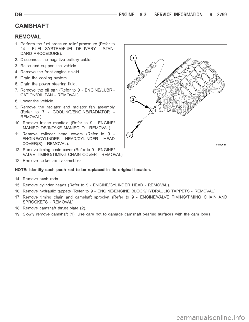
18. Remove camshaft thrust plate (2).
19. Slowly remove camshaft (1). Use care not to damage camshaft bearing surfaces with the cam lobes.
Page 2110 of 5267
20. Fill engine crankcase with the proper oil to the correct level (Refer to9 - ENGINE/LUBRICATION/OIL - STAN-
DARD PROCEDURE).
21. Connect the negative battery cable.
22. Start the vehicle and inspect for leaks.
Page 2148 of 5267
PIPE EXHAUST
REMOVAL
3.7L/4.7L/5.7L ENGINE
1. Raise and support the vehicle.
2. Saturate the bolts and nuts with heat valve lubricant. Allow 5 minutes for penetration.
3. Remove exhaust pipe to manifold bolts and nuts.
4. Remove the clamp nuts.
5. Remove the exhaust pipe.
5.9L DIESEL
1. Disconnect the battery negative cables.
2. Raise and support the vehicle on a hoist.
3. Saturate the bolts and nuts with heat valve lubri-
cant. Allow 5 minutes for penetration.
4. Remove the exhaust pipe-to-extension pipe clamp.
Separate the exhaust pipe and extension pipe.
5. Remove the exhaust pipe-to-turbocharger elbow
clamp and discard.
6. Remove the exhaust pipe from the transmission
support.
8.3L ENGINE
1. Raise and support the vehicle.
2. Saturate the bolts and nuts with heat valve lubri-
cant. Allow 5 minutes for penetration.
3. Remove clamp nuts.
4. Remove exhaust pipe isolators.
5. Rotate the exhaust pipes to remove from the
muffle.
Page 2149 of 5267

INSPECTION
Discard rusted clamps, broken or worn supports and attaching parts. Replace a component with original equipment
parts, or equivalent. This will assure proper alignment with other parts in the system and provide acceptable exhaust
noise levels.
INSTALLATION
3.7L/4.7L/5.7L ENGINE
1. Position the exhaust pipe for proper clearance with the frame and underbody parts. A minimum clearance of 25
mm (1.0 in.) is required.
2. Position the exhaust pipe to manifold. Install the bolts and nuts. Tighten the nuts to 31 Nꞏm (23 ft. lbs.) torque.
3. Tighten the clamp nuts to 54 Nꞏm (40 ft. lbs.) torque.
4. Lower the vehicle.
5. Start the engine and inspect for exhaust leaks and exhaust system contact with the body panels. Adjust the
alignment, if needed.
5.9L DIESEL
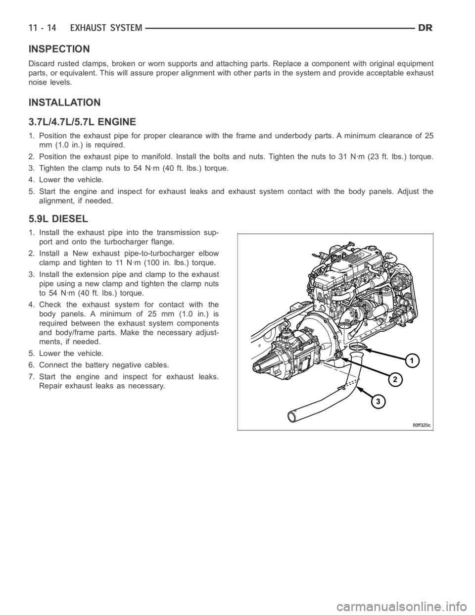
1. Install the exhaust pipe into the transmission sup-
port and onto the turbocharger flange.
2. Install a New exhaust pipe-to-turbocharger elbow
clamp and tighten to 11 Nꞏm (100 in. lbs.) torque.
3. Install the extension pipe and clamp to the exhaust
pipe using a new clamp and tighten the clamp nuts
to 54 Nꞏm (40 ft. lbs.) torque.
4. Check the exhaust system for contact with the
body panels. A minimum of 25 mm (1.0 in.) is
required between the exhaust system components
and body/frame parts. Make the necessary adjust-
ments, if needed.
5. Lower the vehicle.
6. Connect the battery negative cables.
7. Start the engine and inspect for exhaust leaks.
Repair exhaust leaks as necessary.