Page 2170 of 5267

DIAGNOSIS AND TESTING
CHARGE AIR COOLER SYSTEM - LEAKS
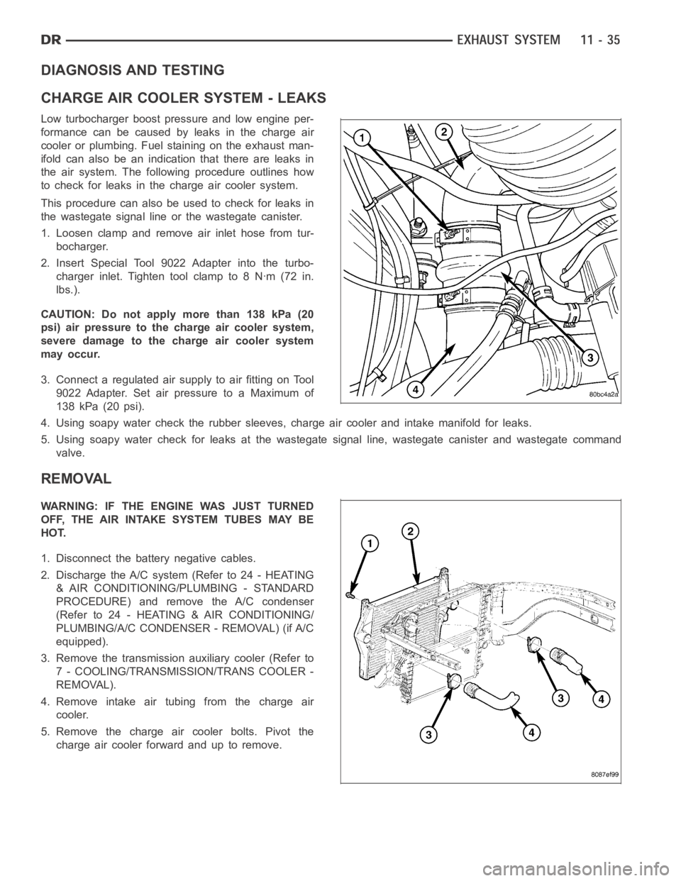
Low turbocharger boost pressure and low engine per-
formance can be caused by leaks in the charge air
cooler or plumbing. Fuel staining on the exhaust man-
ifold can also be an indication that there are leaks in
the air system. The followingprocedure outlines how
to check for leaks in the charge air cooler system.
This procedure can also be used to check for leaks in
the wastegate signal line or the wastegate canister.
1. Loosen clamp and remove air inlet hose from tur-
bocharger.
2. Insert Special Tool 9022 Adapter into the turbo-
charger inlet. Tighten tool clamp to 8 Nꞏm (72 in.
lbs.).
CAUTION: Do not apply more than 138 kPa (20
psi) air pressure to the charge air cooler system,
severe damage to the charge air cooler system
may occur.
3. Connect a regulated air supply to air fitting on Tool
9022 Adapter. Set air pressure to a Maximum of
138 kPa (20 psi).
4. Using soapy water check the rubber sleeves, charge air cooler and intakemanifold for leaks.
5. Using soapy water check for leaks at the wastegate signal line, wastegate canister and wastegate command
valve.
REMOVAL
WARNING: IF THE ENGINE WAS JUST TURNED
OFF, THE AIR INTAKE SYSTEM TUBES MAY BE
HOT.
1. Disconnect the battery negative cables.
2. Discharge the A/C system (Refer to 24 - HEATING
& AIR CONDITIONING/PLUMBING - STANDARD
PROCEDURE) and remove the A/C condenser
(Refer to 24 - HEATING & AIR CONDITIONING/
PLUMBING/A/C CONDENSER - REMOVAL) (if A/C
equipped).
3. Remove the transmission auxiliary cooler (Refer to
7 - COOLING/TRANSMISSION/TRANS COOLER -
REMOVAL).
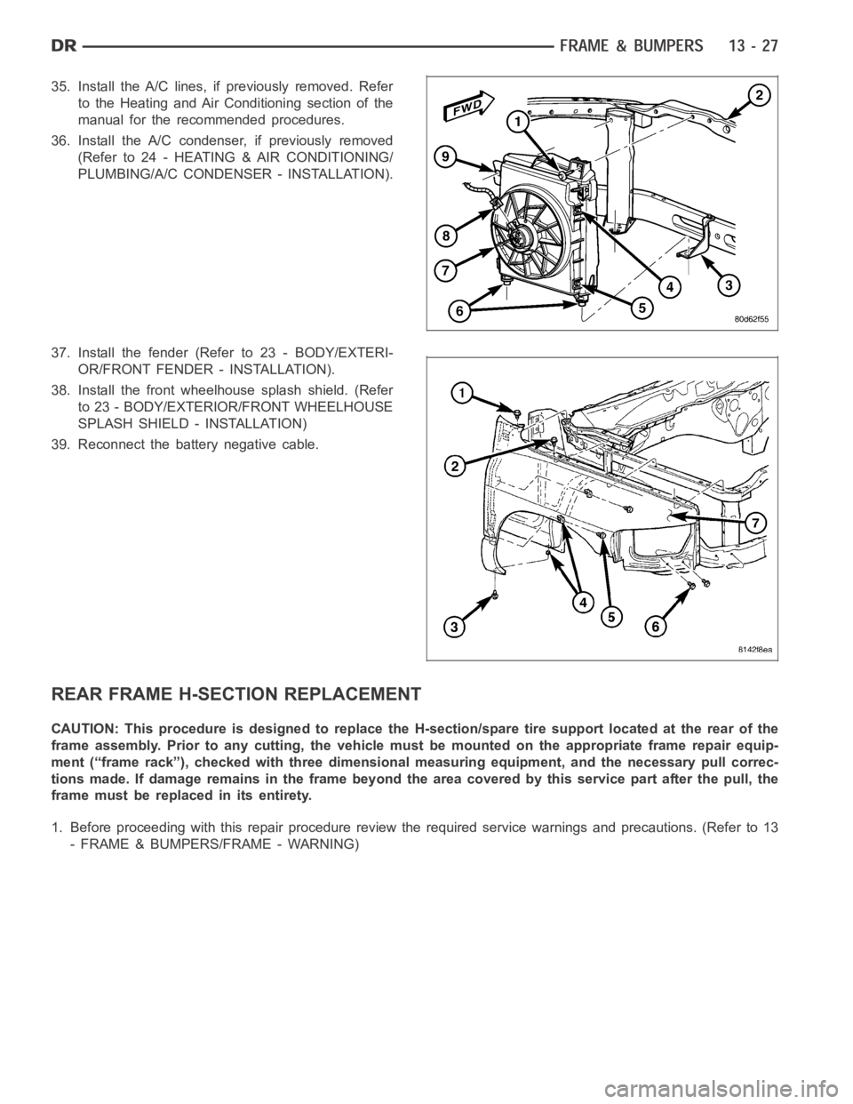
4. Remove intake air tubing from the charge air
cooler.
5. Remove the charge air cooler bolts. Pivot the
charge air cooler forward and up to remove.
Page 2172 of 5267
2. Install the air intake system tubes to the charge air
cooler. With the clamps in position, tighten the
clamps to 11 Nꞏm (95 in. lbs.) torque.
3. Install the transmission auxiliary cooler (if
equipped) (Refer to 7 - COOLING/TRANSMIS-
SION/TRANS COOLER - INSTALLATION).
4. Install the A/C condenser (if A/C equipped) (Refer
to 24 - HEATING & AIR CONDITIONING/PLUMB-
ING/A/C CONDENSER - INSTALLATION).
Recharge A/C system (Refer to 24 - HEATING &
AIR CONDITIONING/PLUMBING - STANDARD
PROCEDURE).
5. Connect the battery negative cables.
6. Start engine and check for boost system leaks.
Page 2192 of 5267
2. Disconnect and isolate the battery negative cable.
3. Remove the front wheelhouse splash shield (Refer
to 23 - BODY/EXTERIOR/FRONT WHEELHOUSE
SPLASH SHIELD - REMOVAL).
4. Remove the fender (Refer to 23 - BODY/EXTERI-
OR/FRONT FENDER - REMOVAL).
5. Remove the A/C condenser, if required (Refer to 24
- HEATING & AIR CONDITIONING/PLUMBING/A/C
CONDENSER - REMOVAL).
6. Remove the A/C lines, if required. Refer to the
Heating and Air Conditioning section of the manual
for recommended procedures.
7. Remove the radiator assembly (4) (Refer to 7 -
COOLING/ENGINE/RADIATOR - REMOVAL).
Page 2200 of 5267

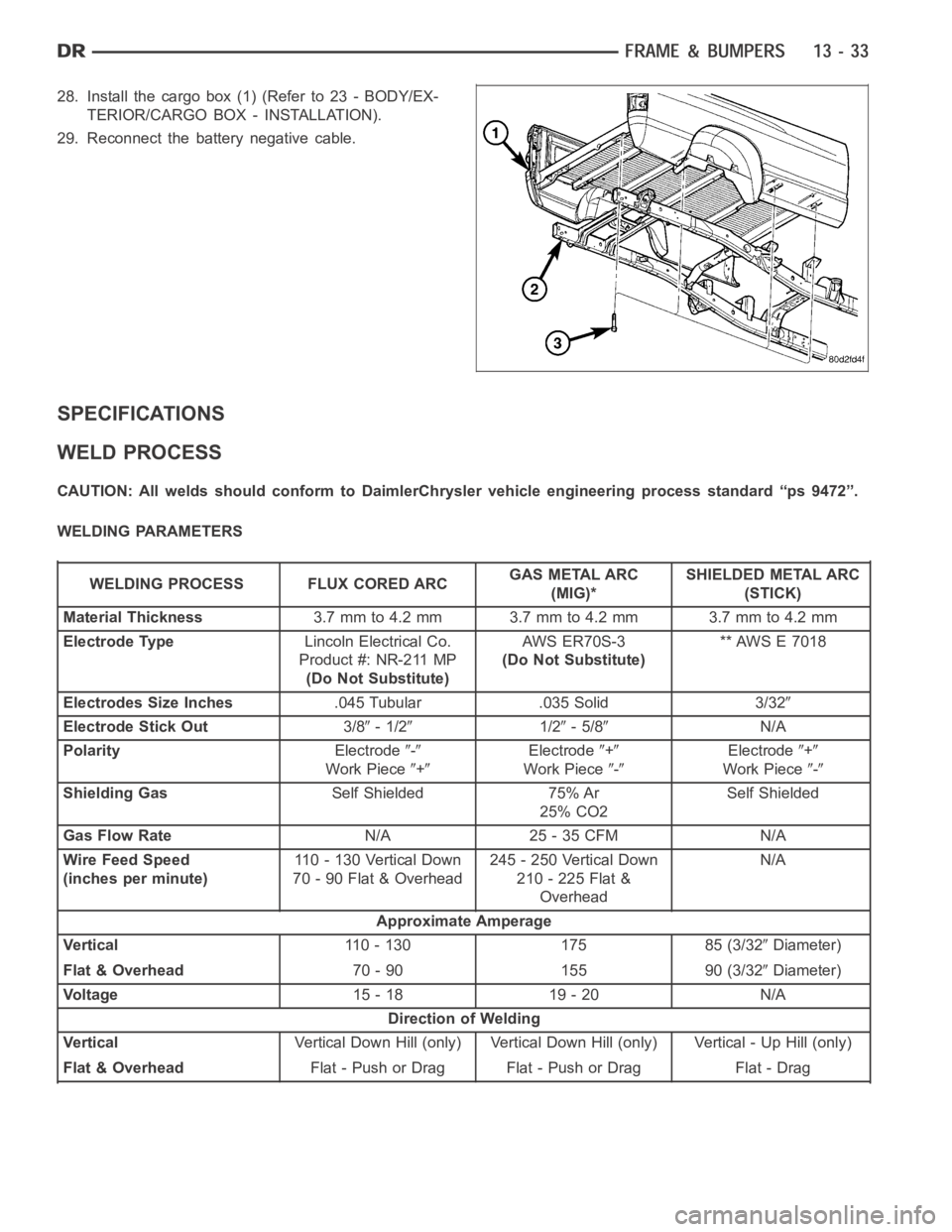
35. Install the A/C lines, if previously removed. Refer
to the Heating and Air Conditioning section of the
manual for the recommended procedures.
36. Install the A/C condenser, if previously removed
(Refer to 24 - HEATING & AIR CONDITIONING/
PLUMBING/A/C CONDENSER - INSTALLATION).
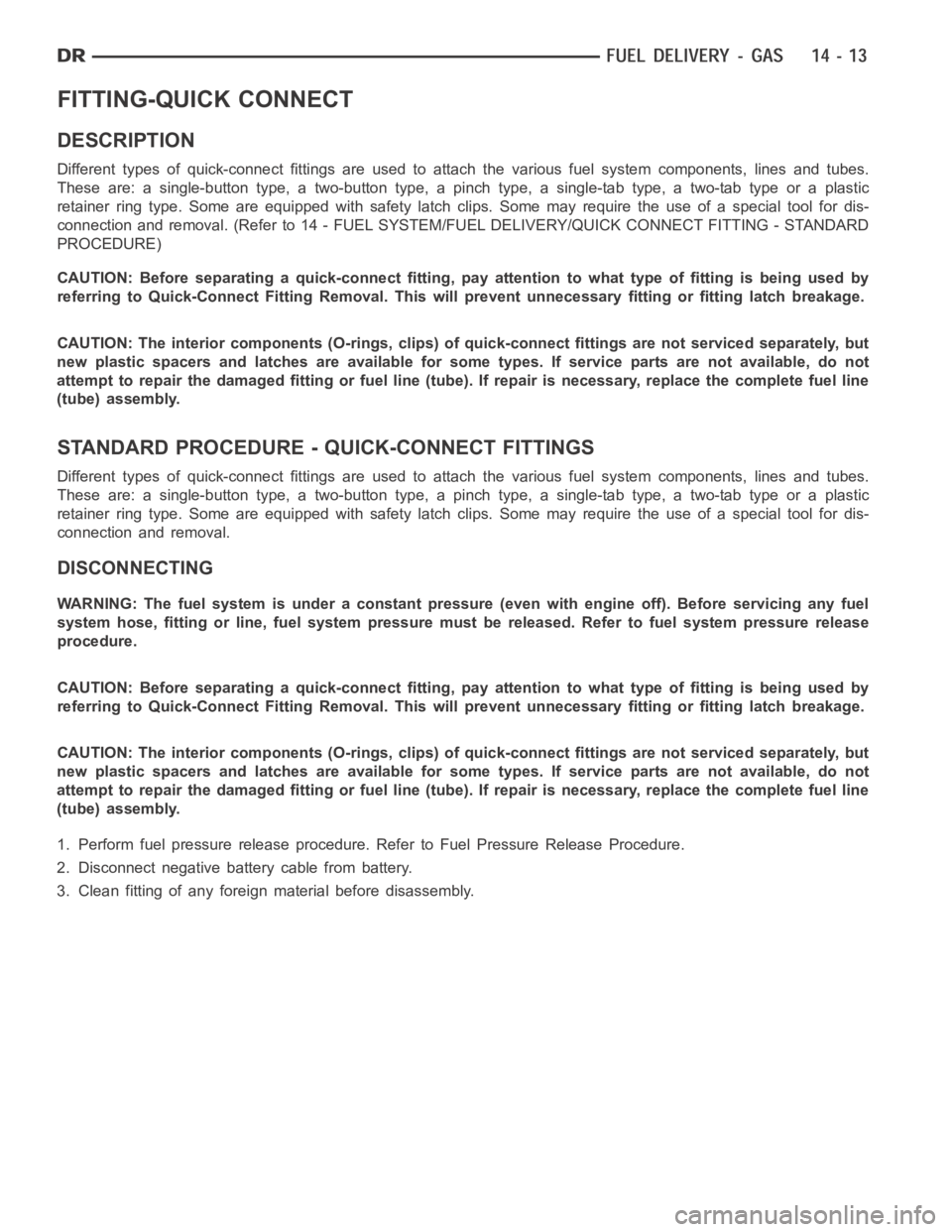
37. Install the fender (Refer to 23 - BODY/EXTERI-
OR/FRONT FENDER - INSTALLATION).
38. Install the front wheelhouse splash shield. (Refer
to 23 - BODY/EXTERIOR/FRONT WHEELHOUSE
SPLASH SHIELD - INSTALLATION)
39. Reconnect the battery negative cable.
REAR FRAME H-SECTION REPLACEMENT
CAUTION: This procedure is designed to replace the H-section/spare tire support located at the rear of the
frame assembly. Prior to any cutting, the vehicle must be mounted on the appropriate frame repair equip-
ment (“frame rack”), checked with three dimensional measuring equipment, and the necessary pull correc-
tions made. If damage remains in the frame beyond the area covered by this service part after the pull, the
frame must be replaced in its entirety.
1. Before proceeding with this repair procedure review the required service warnings and precautions. (Refer to 13
- FRAME & BUMPERS/FRAME - WARNING)
Page 2201 of 5267
2. Disconnect and isolate the battery negative cable.
3. Remove the cargo box (1) (Refer to 23 - BODY/
EXTERIOR/CARGO BOX - REMOVAL).
4. Removethetrailerhitch(1)(Referto13-FRAME
& BUMPERS/FRAME/TRAILER HITCH -
REMOVAL).
Page 2206 of 5267

28. Install the cargo box (1) (Refer to 23 - BODY/EX-
TERIOR/CARGO BOX - INSTALLATION).
29. Reconnect the battery negative cable.
SPECIFICATIONS
WELD PROCESS
CAUTION: All welds should conform to DaimlerChrysler vehicle engineering process standard “ps 9472”.
WELDING PARAMETERS
WELDING PROCESS FLUX CORED ARCGAS METAL ARC
(MIG)*SHIELDED METAL ARC
(STICK)
Material Thickness3.7mmto4.2mm 3.7mmto4.2mm 3.7mmto4.2mm
Electrode TypeLincoln Electrical Co.
Product #: NR-211 MP
(Do Not Substitute)AWS ER70S-3
(Do Not Substitute)** AWS E 7018
Electrodes Size Inches.045 Tubular .035 Solid 3/32
Electrode Stick Out3/8-1/21/2-5/8N/A
PolarityElectrode
-
Work Piece+
Electrode+
Work Piece-
Electrode+
Work Piece-
Shielding GasSelf Shielded 75% Ar
25% CO2Self Shielded
Gas Flow RateN/A 25 - 35 CFM N/A
Wire Feed Speed
(inches per minute)110-130VerticalDown
70 - 90 Flat & Overhead245 - 250 Vertical Down
210 - 225 Flat &
OverheadN/A
Approximate Amperage
Ve r t i c a l110 - 130 175 85 (3/32
Diameter)
Flat & Overhead70 - 90 155 90 (3/32
Diameter)
Vo l t a g e15 - 18 19 - 20 N/A
Direction of Welding
Ve r t i c a lVertical Down Hill (only) Vertical Down Hill (only) Vertical - Up Hill (only)
Flat & OverheadFlat - Push or Drag Flat - Push or Drag Flat - Drag
Page 2242 of 5267

8. Connect other end of jumper wire to positive side of battery.
9. Connect one end of a second jumper wire to remaining injector terminal.
CAUTION: Powering an injector for more than a few seconds will permanentlydamage the injector.
10. Momentarily touch other end of jumper wire to negative terminal of battery for no more than a few seconds.
11. Place a rag or towel below fuel line quick-connect fitting at fuel rail.
12. Disconnect quick-connect fitting at fuel rail. Refer to Quick-Connect Fittings.
13. Return fuel pump relay to PDC.
14. One or more Diagnostic Trouble Codes (DTC’s) may have been stored in PCMmemory due to fuel pump relay
removal. The DRB
scantoolmustbeusedtoeraseaDTC.
STANDARD PROCEDURE - DRAINING FUEL TANK - EXCEPT DIESEL
WARNING: The fuel system may be under constant fuel pressure even with the engine off. This pressure
must be released before servicing fuel tank.
Two different procedures may be used to drain fuel tank: through the fuel fill fitting on tank, or using a diagnostic
scan tool to activate the fuel pump relay. Due to a one-way check valve installed into the fuel fill opening fitting at
the tank, the tank cannot be drained conventionally at the fill cap.
The quickest draining procedure involves removing the rubber fuel fill hose at the fuel tank.
As an alternative procedure, the electric fuel pump may be activated allowingtanktobedrainedatfuelrailcon-
nection. Refer to diagnostic scan tool for fuel pump activation procedures. Before disconnecting fuel line at fuel rail,
release fuel pressure. Refer to the Fuel System Pressure Release Procedure for procedures. Attach end of special
test hose tool number 6631 or 6539 at fuel rail disconnection (tool number 6631isusedon5/16”fuellineswhile
tool number 6539 is used on 3/8” fuel lines). Position opposite end of this hose tool to an approved gasoline drain-
ing station. Activate fuel pump and drain tank until empty.
If electric fuel pump is not operating, fuel must be drained through fuel fill fitting at tank. Refer to following proce-
dures.
1. Release fuel system pressure.
2. Raise vehicle.
3. Thoroughly clean area around fuel fill fitting and rubber fuel fill hoseat tank.
4. If vehicle is equipped with 4 doors and a 6 foot (short) box, remove left-rear tire/wheel.
5. Loosen clamp and disconnect rubber fuel fill hose at tank fitting. Usingan approved gas holding tank, drain fuel
tank through this fitting.
SPECIFICATIONS
FUEL SYSTEM PRESSURE
58 psi +/- 2 psi
TORQUE - EXCEPT DIESEL
DESCRIPTION N-m Ft. Lbs. In. Lbs.
Accelerator Pedal Bracket
Mounting12 - 105
Accelerator Pedal Position
Sensor Bracket-to-Battery
Tray Bolts3-30
Crankshaft Position
Sensor - 3.7L28 21 -
Crankshaft Position
Sensor - 4.7L28 21 -
Page 2250 of 5267

FITTING-QUICK CONNECT
DESCRIPTION
Different types of quick-connect fittings are used to attach the various fuel system components, lines and tubes.
These are: a single-button type, a two-button type, a pinch type, a single-tab type, a two-tab type or a plastic
retainer ring type. Some are equipped with safety latch clips. Some may require the use of a special tool for dis-
connection and removal. (Refer to 14 - FUEL SYSTEM/FUEL DELIVERY/QUICK CONNECT FITTING - STANDARD
PROCEDURE)
CAUTION: Before separating a quick-connect fitting, pay attention to whattypeoffittingisbeingusedby
referring to Quick-Connect Fitting Removal. This will prevent unnecessary fitting or fitting latch breakage.
CAUTION: The interior components (O-rings, clips) of quick-connect fittings are not serviced separately, but
new plastic spacers and latches are available for some types. If service parts are not available, do not
attempt to repair the damaged fitting or fuel line (tube). If repair is necessary, replace the complete fuel line
(tube) assembly.
STANDARD PROCEDURE - QUICK-CONNECT FITTINGS
Different types of quick-connect fittings are used to attach the various fuel system components, lines and tubes.
These are: a single-button type, a two-button type, a pinch type, a single-tab type, a two-tab type or a plastic
retainer ring type. Some are equipped with safety latch clips. Some may require the use of a special tool for dis-
connection and removal.
DISCONNECTING
WARNING: The fuel system is under a constant pressure (even with engine off). Before servicing any fuel
system hose, fitting or line, fuel system pressure must be released. Referto fuel system pressure release
procedure.
CAUTION: Before separating a quick-connect fitting, pay attention to whattypeoffittingisbeingusedby
referring to Quick-Connect Fitting Removal. This will prevent unnecessary fitting or fitting latch breakage.
CAUTION: The interior components (O-rings, clips) of quick-connect fittings are not serviced separately, but
new plastic spacers and latches are available for some types. If service parts are not available, do not
attempt to repair the damaged fitting or fuel line (tube). If repair is necessary, replace the complete fuel line
(tube) assembly.
1. Perform fuel pressure release procedure. Refer to Fuel Pressure Release Procedure.
2. Disconnect negative battery cable from battery.
3. Clean fitting of any foreign material before disassembly.