Page 2057 of 5267
MANIFOLD-INTAKE
DIAGNOSIS AND TESTING
INTAKE MANIFOLD LEAKS
An intake manifold air leak is characterized by lower than normal manifoldvacuum, rough idle, or engine misfire.
WARNING: USE EXTREME CAUTION WHEN THE ENGINE IS OPERATING. DO NOT STAND IN ADIRECT LINE
WITH THE FAN. DO NOT PUT YOUR HANDS NEAR THE PULLEYS, BELT OR THE FAN. DO NOT WEAR
LOOSE CLOTHING.
1. Start the engine.
2. Spray a small stream of water (Spray Bottle) at the suspected leak area.
3. If engine RPM’S change, the area of the suspected leak has been found.
4. Repair as required.
REMOVAL
NOTE: Care must be taken to protect the intake
manifold powder coating from scrapes and abra-
sions.
1. Perform the fuel system pressure release proce-
dure,before attempting any repairs.(Refer to 14
- FUEL SYSTEM/FUEL DELIVERY - STANDARD
PROCEDURE - FUEL SYSTEM PRESSURE
RELEASE PROCEDURE).
2. Disconnect negative battery cable.
3. Disconnect throttle body air inlet duct, IAT sensor,
CCV hose and remove air cleaner cover (Refer to
9 - ENGINE/AIR INTAKE SYSTEM - REMOVAL).
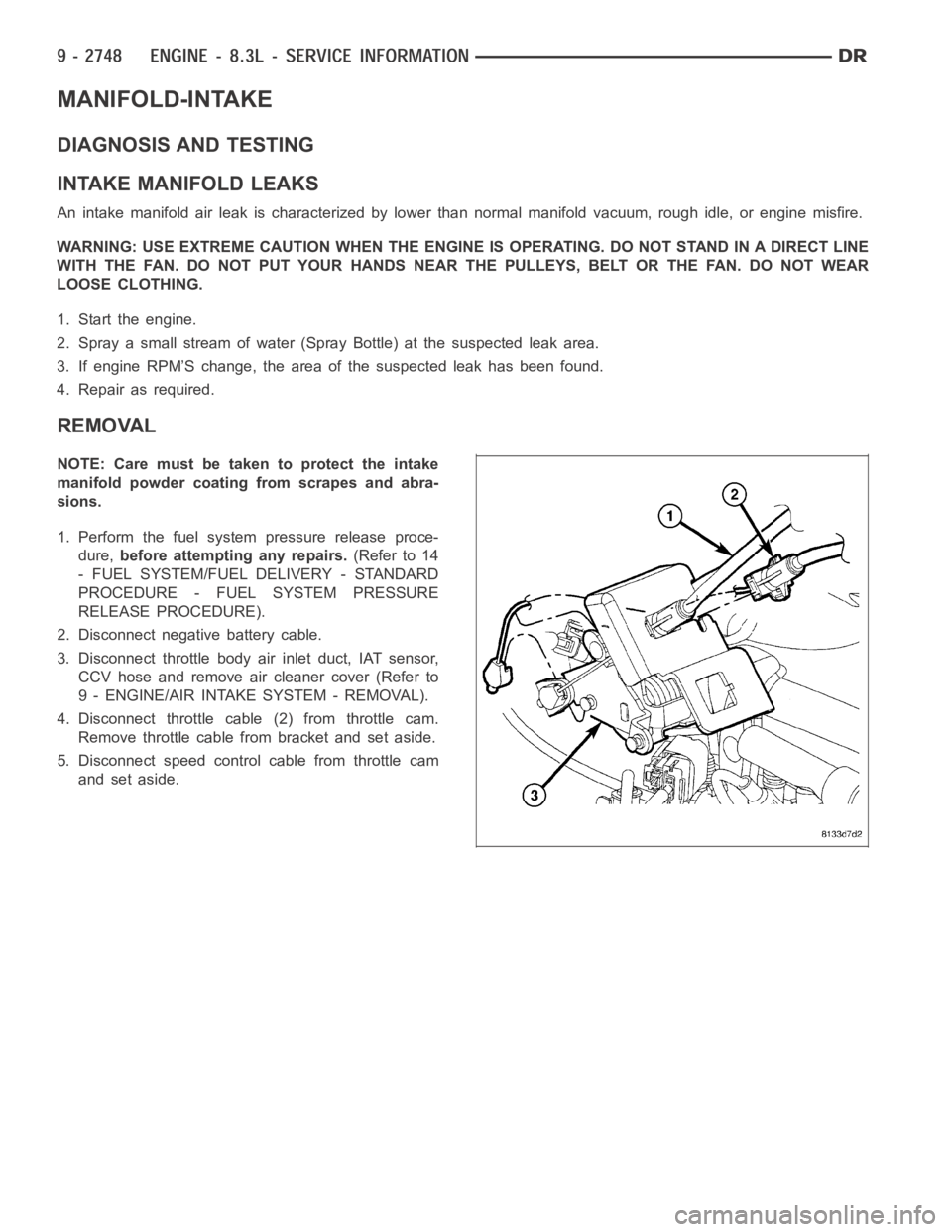
4. Disconnect throttle cable (2) from throttle cam.
Remove throttle cable from bracket and set aside.
5. Disconnect speed control cable from throttle cam
and set aside.
Page 2062 of 5267
10. Reconnect the following electrical connectors:
Left cylinder head fuel injectors
Engine Coolant Temperature (ECT) Sensor
MAP sensor
Idle Speed Control
Throttle Position Sensor
Right cylinder head fuel injectors
11. Install air cleaner cover assembly, connect throttle
body air inlet hose, CCV hose and connect the
Intake Air Temperature Sensor (Refer to 9 -
ENGINE/AIR INTAKE SYSTEM - INSTALLATION).
12. Connect negative battery cable.
13. With the Scan Tool, use the ASD Fuel System
Test to pressurize fuel system to check for leaks.
CAUTION: When using the ASD Fuel System Test,
the Auto Shutdown (ASD) relay will remain ener-
gized for 7 minutes or until the ignition switch is
turned to the OFF position, or Stop All Test is selected.
Page 2063 of 5267
MANIFOLD-EXHAUST
REMOVAL
NOTE: Care must be taken to protect the cylinder
head covers powder coating from scrapes and
abrasions. This procedure covers either the left or
right exhaust manifold.
1. Disconnect negative battery cable.
NOTE: When servicing the right exhaust manifold
it is necessary to remove the upper oil dip stick
tube fastener and position the tube aside.
2. Raise vehicle on hoist.
3. Loosen and remove the fasteners from the exhaust
pipe to exhaust manifold.
4. Separate exhaust pipe from the exhaust manifold.
5. Lower the vehicle.
6. Disconnect the spark plug wires from the spark
plugs and set aside.
7. Remove manifold heat shield from exhaust mani-
fold ,.
NOTE: Note the location of exhaust manifold studs
and bolts for proper installation.
8. Remove studs and bolts attaching manifold to cyl-
inder head and remove manifold ,.
Page 2065 of 5267
3. Install the spark plug wires.
4. Raise vehicle on hoist.
5. Connect exhaust pipe to exhaust manifold. Tighten
fastenersto34Nꞏm(25ft.lbs.).
6. Lower vehicle.
7. Connect negative battery cable.
Page 2066 of 5267
HEAD(S)-CYLINDER
REMOVAL - CYLINDER HEAD(S)
NOTE: Care must be taken to protect the intake
manifold and cylinder head covers powder coating
from scrapes and abrasions. This procedure cov-
ers either the left or right cylinder head.
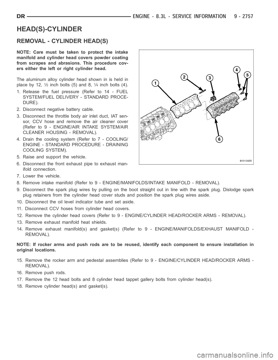
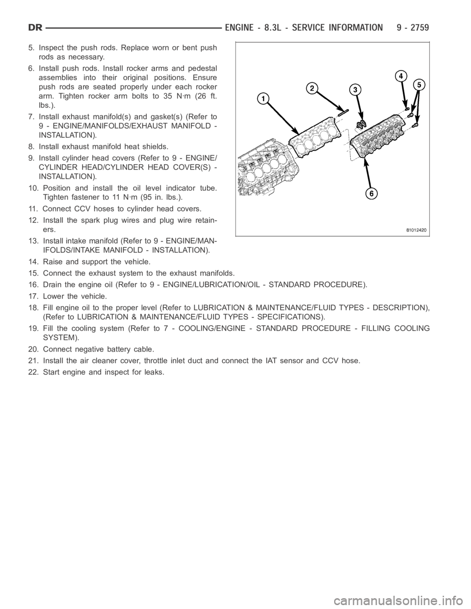
The aluminum alloy cylinder head shown in is held in
place by 12,
1⁄2inch bolts (5) and 8,1⁄4inch bolts (4).
1. Release the fuel pressure (Refer to 14 - FUEL
SYSTEM/FUEL DELIVERY - STANDARD PROCE-
DURE).
2. Disconnect negative battery cable.
3. Disconnect the throttle body air inlet duct, IAT sen-
sor, CCV hose and remove the air cleaner cover
(Refer to 9 - ENGINE/AIR INTAKE SYSTEM/AIR
CLEANER HOUSING - REMOVAL).
4. Drain the cooling system (Refer to 7 - COOLING/
ENGINE - STANDARD PROCEDURE - DRAINING
COOLING SYSTEM).
5. Raise and support the vehicle.
6. Disconnect the front exhaust pipe to exhaust man-
ifold connection.
7. Lower the vehicle.
8. Remove intake manifold (Refer to 9 - ENGINE/MANIFOLDS/INTAKE MANIFOLD-REMOVAL).
9. Disconnect the spark plug wires by pulling on the boot straight out in line with the spark plug. Dislodge spark
plug retainers from the cylinder head cover studs and position the spark plug wires aside.
10. Disconnect the oil level indicator tube and set aside.
11. Disconnect CCV hoses from cylinder head covers.
12. Remove the cylinder head covers (Refer to 9 - ENGINE/CYLINDER HEAD/ROCKER ARMS - REMOVAL).
13. Remove exhaust manifold heat shields.
14. Remove exhaust manifold(s) and gasket(s) (Refer to 9 - ENGINE/MANIFOLDS/EXHAUST MANIFOLD -
REMOVAL).
NOTE: If rocker arms and push rods are to be reused, identify each componentto ensure installation in
original locations.
15. Remove the rocker arm and pedestal assemblies (Refer to 9 - ENGINE/CYLINDER HEAD/ROCKER ARMS -
REMOVAL).
16. Remove push rods.
17. Remove the 12 head bolts and 8 cylinder head tappet gallery bolts from cylinder head(s).
18. Remove cylinder head(s) and gasket(s).
Page 2068 of 5267
5. Inspect the push rods. Replace worn or bent push
rods as necessary.
6. Install push rods. Install rocker arms and pedestal
assemblies into their original positions. Ensure
push rods are seated properly under each rocker
arm.Tightenrockerarmboltsto35Nꞏm(26ft.
lbs.).
7. Install exhaust manifold(s) and gasket(s) (Refer to
9 - ENGINE/MANIFOLDS/EXHAUST MANIFOLD -
INSTALLATION).
8. Install exhaust manifold heat shields.
9. Install cylinder head covers (Refer to 9 - ENGINE/
CYLINDER HEAD/CYLINDER HEAD COVER(S) -
INSTALLATION).
10. Position and install the oil level indicator tube.
Tighten fastener to 11 Nꞏm (95 in. lbs.).
11. Connect CCV hoses to cylinder head covers.
12. Install the spark plug wires and plug wire retain-
ers.
13. Install intake manifold (Refer to 9 - ENGINE/MAN-
IFOLDS/INTAKE MANIFOLD - INSTALLATION).
14. Raise and support the vehicle.
15. Connect the exhaust systemto the exhaust manifolds.
16. Drain the engine oil (Refer to 9 - ENGINE/LUBRICATION/OIL - STANDARD PROCEDURE).
17. Lower the vehicle.
18. Fill engine oil to the proper level (Refer to LUBRICATION & MAINTENANCE/FLUID TYPES - DESCRIPTION),
(Refer to LUBRICATION & MAINTENANCE/FLUID TYPES - SPECIFICATIONS).
19. Fill the cooling system (Refer to 7 - COOLING/ENGINE - STANDARD PROCEDURE - FILLING COOLING
SYSTEM).
20. Connect negative battery cable.
21. Install the air cleaner cover, throttle inlet duct and connect the IAT sensor and CCV hose.
22. Start engine and inspect for leaks.
Page 2072 of 5267
SPRINGS/SEALS-VALVE
DIAGNOSIS AND TESTING
VA LV E S P R I N G T E S T I N G
The valve springs should be tested whenever
removed for inspection, reconditioning, or replace-
ment.
1. Obtain specifications for spring tension at specified
spring length (Refer to 9 - ENGINE - SPECIFICA-
TIONS).
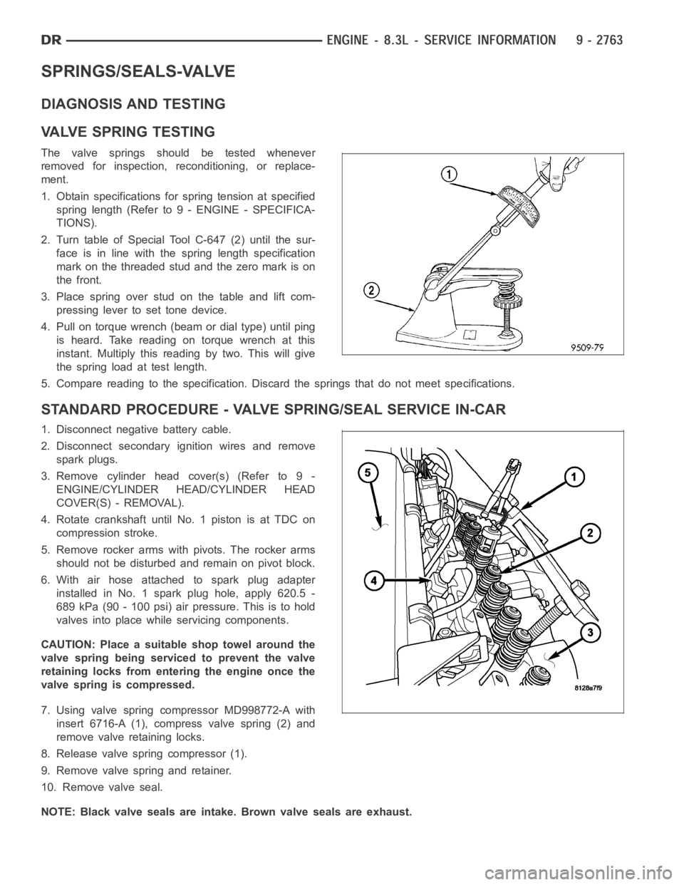
2. Turn table of Special Tool C-647 (2) until the sur-
face is in line with the spring length specification
mark on the threaded stud and the zero mark is on
the front.
3.Placespringoverstudonthetableandliftcom-
pressing lever to set tone device.
4. Pull on torque wrench (beam or dial type) until ping
is heard. Take reading on torque wrench at this
instant. Multiply this reading by two. This will give
the spring load at test length.
5. Compare reading to the specification. Discard the springs that do not meet specifications.
STANDARD PROCEDURE - VALVE SPRING/SEAL SERVICE IN-CAR
1. Disconnect negative battery cable.
2. Disconnect secondary ignition wires and remove
spark plugs.
3. Remove cylinder head cover(s) (Refer to 9 -
ENGINE/CYLINDER HEAD/CYLINDER HEAD
COVER(S) - REMOVAL).
4. Rotate crankshaft until No. 1 piston is at TDC on
compression stroke.
5. Remove rocker arms with pivots. The rocker arms
should not be disturbed and remain on pivot block.
6. With air hose attached to spark plug adapter
installed in No. 1 spark plug hole, apply 620.5 -
689 kPa (90 - 100 psi) air pressure. This is to hold
valves into place while servicing components.
CAUTION: Place a suitable shop towel around the
valve spring being serviced to prevent the valve
retaining locks from entering the engine once the
valve spring is compressed.
7. Using valve spring compressor MD998772-A with
insert 6716-A (1), compress valve spring (2) and
remove valve retaining locks.
8. Release valve spring compressor (1).
9. Remove valve spring and retainer.
10. Remove valve seal.
NOTE: Black valve seals are intake. Brown valve seals are exhaust.
Page 2073 of 5267
11. The intake and exhaust valve stem seals should be pushed firmly and squarely over the valve guide using the
valve stem as guide. Push seal against top of guide. When installing the valve retainer locks, compress the
springonly enoughto install the locks.
CAUTION: Do not pinch seal between retainer and top of valve guide.
12. Follow the same procedure on the remaining 9 cylinders.Make sure piston is at TDC on the cylinder the
valve spring is being removed.
13. Remove spark plug adapter tool.
14. Install rocker arm and pedestal assemblies. Ensure push rods are seated properly under each rocker arm.
Tightenrockerarmboltsto35Nꞏm(26ft.lbs.).
15. Install cylinder head covers (Refer to 9 - ENGINE/CYLINDER HEAD/CYLINDERHEADCOVER(S)-INSTAL-
LATION).
16. Install spark plugs and connect secondary ignition wires.
17. Connect negative battery cable.
REMOVAL
NOTE: Before replacing parts, inspect all related
valvetrain components for damage to prevent
engine misfire.
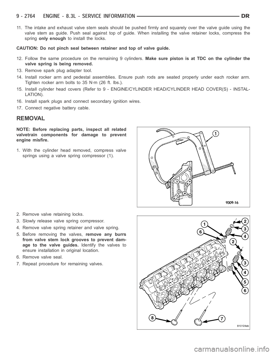
1. With the cylinder head removed, compress valve
springs using a valve spring compressor (1).
2. Remove valve retaining locks.
3. Slowly release valve spring compressor.
4. Remove valve spring retainer and valve spring.
5. Before removing the valves,remove any burrs
from valve stem lock grooves to prevent dam-
age to the valve guides.Identify the valves to
ensure installation in original location.
6. Remove valve seal.
7. Repeat procedure for remaining valves.