2006 DODGE RAM SRT-10 battery
[x] Cancel search: batteryPage 1955 of 5267
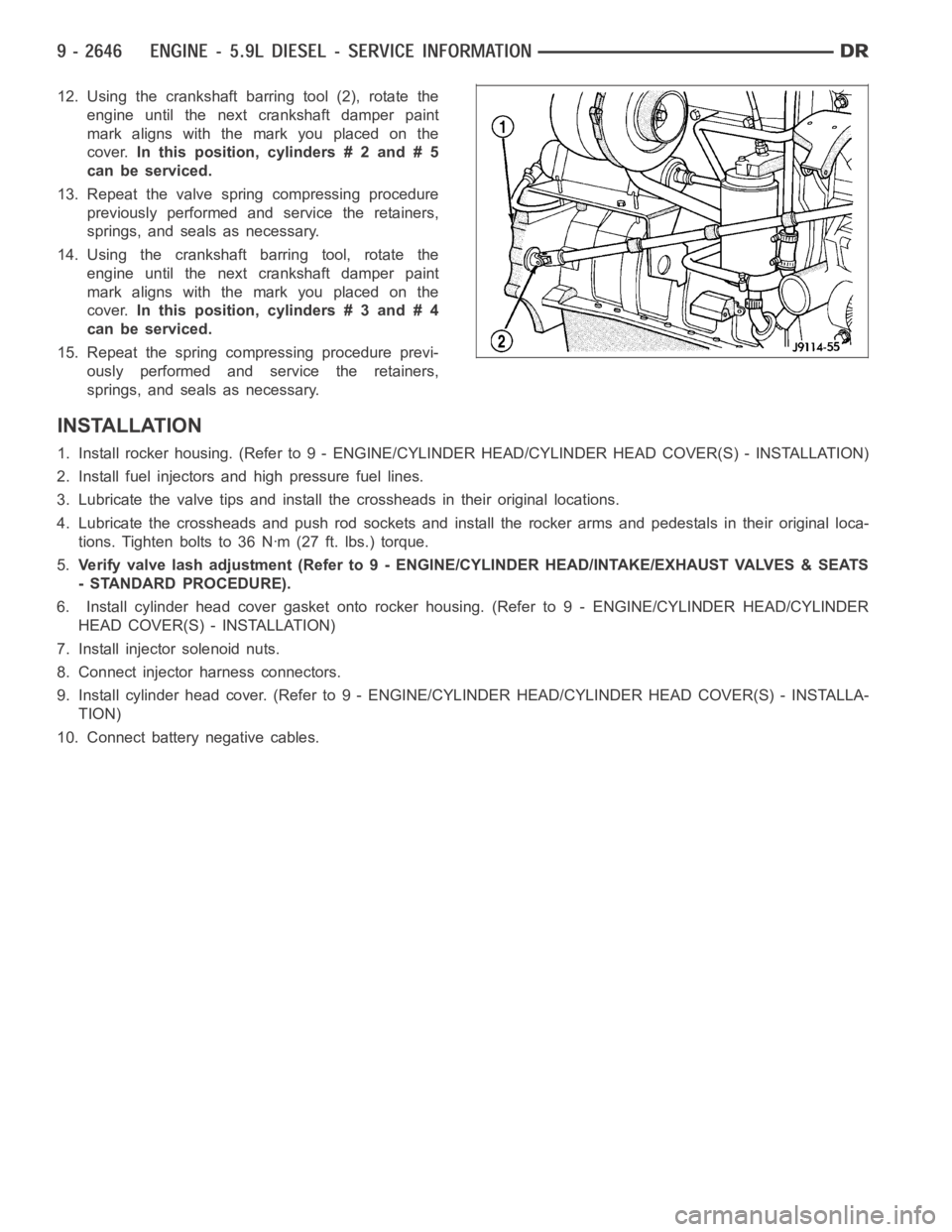
12. Using the crankshaft barring tool (2), rotate the
engine until the next crankshaft damper paint
mark aligns with the mark you placed on the
cover.In this position, cylinders # 2 and # 5
can be serviced.
13. Repeat the valve spring compressing procedure
previously performed and service the retainers,
springs, and seals as necessary.
14. Using the crankshaft barring tool, rotate the
engine until the next crankshaft damper paint
mark aligns with the mark you placed on the
cover.In this position, cylinders # 3 and # 4
can be serviced.
15. Repeat the spring compressing procedure previ-
ously performed and service the retainers,
springs, and seals as necessary.
INSTALLATION
1. Install rocker housing. (Refer to 9 -ENGINE/CYLINDER HEAD/CYLINDER HEAD COVER(S) - INSTALLATION)
2. Install fuel injectors and high pressure fuel lines.
3. Lubricate the valve tips and install the crossheads in their original locations.
4. Lubricate the crossheads and push rod sockets and install the rocker arms and pedestals in their original loca-
tions. Tighten bolts to 36 Nꞏm (27 ft. lbs.) torque.
5.Verify valve lash adjustment (Refer to 9 - ENGINE/CYLINDER HEAD/INTAKE/EXHAUST VALVES & SEATS
- STANDARD PROCEDURE).
6. Install cylinder head cover gasket onto rocker housing. (Refer to 9 - ENGINE/CYLINDER HEAD/CYLINDER
HEAD COVER(S) - INSTALLATION)
7. Install injector solenoid nuts.
8. Connect injector harness connectors.
9. Install cylinder head cover. (Refer to 9 - ENGINE/CYLINDER HEAD/CYLINDER HEAD COVER(S) - INSTALLA-
TION)
10. Connect battery negative cables.
Page 1956 of 5267
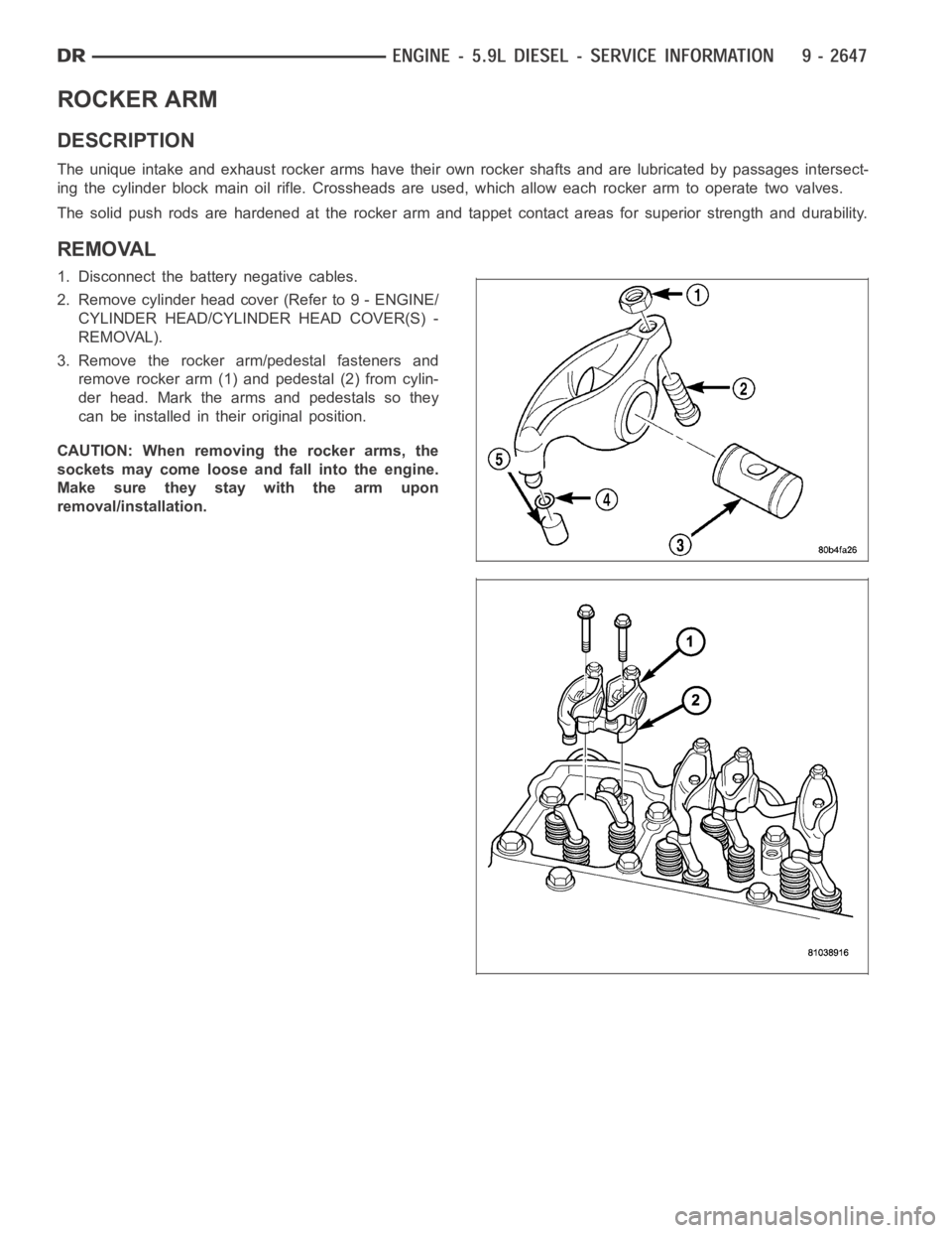
ROCKER ARM
DESCRIPTION
The unique intake and exhaust rocker arms have their own rocker shafts and are lubricated by passages intersect-
ing the cylinder block main oil rifle. Crossheads are used, which allow each rocker arm to operate two valves.
The solid push rods are hardened at the rocker arm and tappet contact areas for superior strength and durability.
REMOVAL
1. Disconnect the battery negative cables.
2. Remove cylinder head cover (Refer to 9 - ENGINE/
CYLINDER HEAD/CYLINDER HEAD COVER(S) -
REMOVAL).
3. Remove the rocker arm/pedestal fasteners and
remove rocker arm (1) and pedestal (2) from cylin-
der head. Mark the arms and pedestals so they
can be installed in their original position.
CAUTION: When removing the rocker arms, the
sockets may come loose and fall into the engine.
Make sure they stay with the arm upon
removal/installation.
Page 1959 of 5267
6. Connect battery negative cables.
Page 1966 of 5267
CAMSHAFT & BEARINGS (IN BLOCK)
REMOVAL
CAMSHAFT BEARINGS
NOTE: Measure the diameter of each bore. If the camshaft bore for the cam bushing is worn beyond the
limit, install a new service bushing. Inspect the rest of the camshaft bores for damage or excessive wear.If
the bores without a bushing are worn beyond the limit, the engine must be removed for machining and
installation of service bushings. If badly worn, replace the cylinder block.
1. Remove the camshaft (Refer to 9 - ENGINE/ENGINE BLOCK/CAMSHAFT & BEARINGS (IN BLOCK) -
REMOVAL).
2. Remove the bushing from the No.1 bore.
3. Mark the cylinder block so you can align the oil hole in the cylinder blockwith the oil hole in the bushing.
CAMSHAFT
1. Disconnect both battery negative cables.
2. Recover A/C refrigerant (if A/C equipped) (Refer to 24 - HEATING & AIR CONDITIONING/PLUMBING - STAN-
DARD PROCEDURE).
3. Raise vehicle on hoist.
4. Drain engine coolant into container suitable for re-use (Refer to 7 - COOLING - STANDARD PROCEDURE).
5. Lower vehicle.
6. Remove radiator upper hose.
7. Remove viscous fan/drive/shroud assembly (Refer to 7 - COOLING/ENGINE/RADIATOR FAN - REMOVAL).
8. Disconnect the coolant recovery bottle hose from the radiator filler neck.
9. Disconnect lower radiator hose from radiator outlet.
10.Automatic Transmission models:Disconnect transmission oil cooler lines from front of radiator using Special
Tool 6931 (unless equipped with finger-release disconnect).
11. Remove radiator mounting screws and lift radiator out of engine compartment.
12. Remove upper radiator support panel.
13. If A/C equipped, disconnect A/C condenser refrigerant lines.
14. Disconnect charge air cooler piping from the cooler inlet and outlet.
15. Remove the two charge air cooler mounting bolts.
16. Remove charge air cooler (and A/C condenser if equipped) from vehicle.
17. Remove accessory drive belt (Refer to 7 - COOLING/ACCESSORY DRIVE/DRIVE BELTS - REMOVAL).
18. Remove accessory drive belt tensioner.
19. Remove the fan support/hub assembly.
20. Remove crankshaft damper and speed indicator ring (Refer to 9 - ENGINE/ENGINE BLOCK/VIBRATION
DAMPER - REMOVAL).
21. Remove the gear cover-to-housing bolts and gently pry the cover away from the housing, taking care not to mar
the sealing surfaces. Remove dust seal with cover.
22. Using Special Tool 7471–B Crankshaft Barring Tool, rotate the crankshaft to align the timing marks on the
crankshaft and the camshaft gears.
23. Remove the cylinder head cover (Refer to 9 - ENGINE/CYLINDER HEAD/CYLINDER HEAD COVER(S) -
REMOVAL).
Page 1971 of 5267
12. Install gear housing cover (Refer to 9 - ENGINE/VALVE TIMING/GEAR HOUSING COVER - INSTALLATION).
Install front crankshaft dust seal.
13. Install the crankshaft damper with the speed indicator ring (Refer to 9- ENGINE/ENGINE BLOCK/VIBRATION
DAMPER - INSTALLATION).
14. Install the fan support/hub assembly Refer to (Refer to 7 - COOLING/ENGINE/RADIATOR FAN - INSTALLA-
TION).
15. Install the power steering pump.
16. Install accessory drive belt tensioner. Torque bolt to 43 Nꞏm (32 ft. lbs.).
17. Install the accessory drive belt (Refer to 7 - COOLING/ACCESSORY DRIVE/DRIVE BELTS - INSTALLATION).
18. Install the charge air cooler (with a/c condenser and auxiliary transmission oil cooler, if equipped) and tighten
the mounting bolts to 2 Nꞏm (17 in. lbs.) torque.
19. Connect charge air cooler inlet and outlet pipes. Tighten clamps to 11 Nꞏm (95 in. lbs.) torque.
20. Install the radiator upper support panel.
21. Close radiator petcock and lower the radiator into the engine compartment. Tighten the mounting bolts to 11
Nꞏm (95 in. lbs.) torque.
22. Raise vehicle on hoist.
23. Connect radiator lower hose and install clamp.
24. Connect transmission auxiliary oil cooler lines (if equipped).
25. Lower vehicle.
26. Install the fandrive/shroud assembly. (Refer to 7 - COOLING/ENGINE/RADIATOR FAN - INSTALLATION)
27. Install the coolant recovery and windshield washer fluid reservoirs to the fan shroud.
28. Connect the coolant recovery hose to the radiator filler neck.
29. Add engine coolant (Refer to 7 - COOLING - STANDARD PROCEDURE).
30. Charge A/C system with refrigerant (if A/C equipped) (Refer to 24 - HEATING & AIR CONDITIONING/PLUMB-
ING - STANDARD PROCEDURE).
31. Connect the battery negative cables.
32. Start engine and check for engine oil and coolant leaks.
Page 1976 of 5267
SEAL - CRANKSHAFT OIL - FRONT
REMOVAL
1. Disconnect both battery negative cables.
2. Raise vehicle on hoist.
3. Partially drain engine coolant into container suitable for re-use (Refer to 7 - COOLING - STANDARD PROCE-
DURE).
4. Lower vehicle.
5. Remove radiator upper hose.
6. Disconnect coolant recovery bottle hose from radiator filler neck.
7. Disconnect windshield washer pump supply hose and electrical connections and lift washer bottle off of fan
shroud.
8. Remove viscous fan/drive assembly. (Refer to 7 - COOLING/ENGINE/RADIATOR FAN - REMOVAL).
9. Remove cooling fan shroud and fan assembly from the vehicle.
10. Remove the accessory drive belt (Refer to 7 - COOLING/ACCESSORY DRIVE/DRIVE BELTS - REMOVAL).
11. Remove the cooling fan support/hub from the front of the engine.
12. Raisethevehicleonhoist.
13. Remove the crankshaft damper and speed indicator ring.
14. Remove power steering pump.
15. Remove accessory drive belt tensioner.
16. Remove the gear cover-to-housing bolts and gen-
tly pry the cover away from the housing, taking
care not to mar the gasket surfaces. Remove
crank seal dust shield with cover.
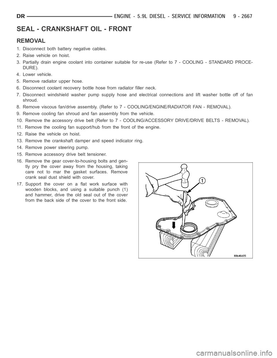
17. Support the cover on a flat work surface with
wooden blocks, and using a suitable punch (1)
and hammer, drive the old seal out of the cover
from the back side of the cover to the front side.
Page 1977 of 5267
INSTALLATION
CAUTION: The seal lip and the sealing surface on
thecrankshaftmustbefreeofalloilresidue,to
prevent leaks. The crankshaft and seal surface
must be completely dry when the seal is installed.
1. Clean cover and housing gasket mating surfaces.
Use a suitable scraper and be careful not to dam-
age the gear housing surface. Remove any old
sealer from the oil seal bore. Thoroughly clean the
front seal area of the crankshaft. Do not sand this
surface. The seal lip and the sealing surface on the
crankshaft must be free from all oil residue to pre-
vent seal leaks.
2. Inspect the gear housing and cover for cracks and
replace if necessary. Carefully straighten any bends
or imperfections in the gear cover with a ball-peen
hammer on a flat surface. Inspect the crankshaft
front journal for any grooves or nicks that would
affect the integrity of the new seal.
3. Apply a bead of Mopar
Stud & Bearing Mount to
the outside diameter of the seal. Do not lubricate the inside diameter of thenewseal.
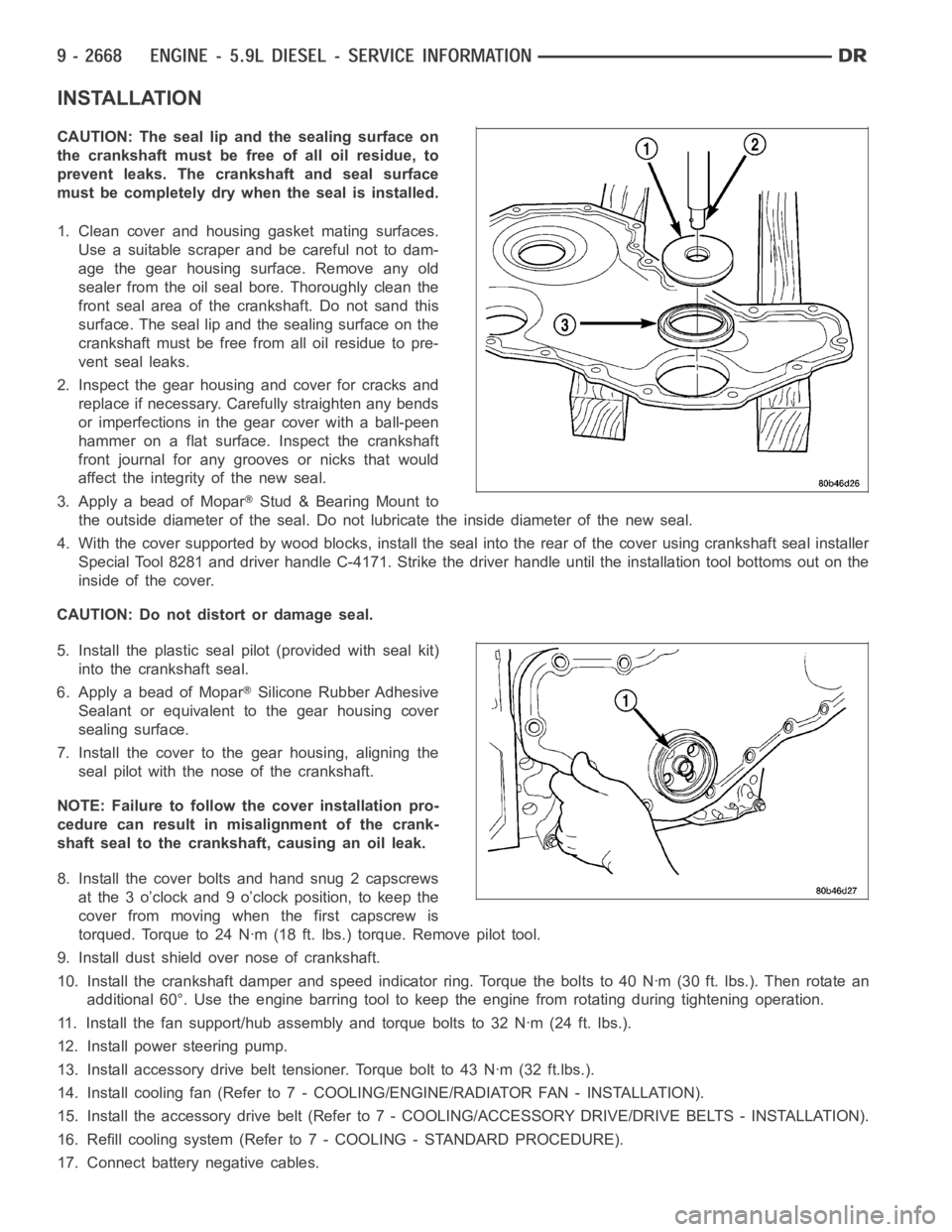
4. With the cover supported by wood blocks, install the seal into the rear ofthe cover using crankshaft seal installer
Special Tool 8281 and driver handle C-4171. Strike the driver handle untilthe installation tool bottoms out on the
inside of the cover.
CAUTION: Do not distort or damage seal.
5. Install the plastic seal pilot (provided with seal kit)
into the crankshaft seal.
6. Apply a bead of Mopar
Silicone Rubber Adhesive
Sealant or equivalent to the gear housing cover
sealing surface.
7. Install the cover to the gear housing, aligning the
seal pilot with the nose of the crankshaft.
NOTE: Failure to follow the cover installation pro-
cedure can result in misalignment of the crank-
shaft seal to the crankshaft, causing an oil leak.
8. Install the cover bolts and hand snug 2 capscrews
at the 3 o’clock and 9 o’clock position, to keep the
cover from moving when the first capscrew is
torqued. Torque to 24 Nꞏm (18 ft. lbs.) torque. Remove pilot tool.
9. Install dust shield over nose of crankshaft.
10. Install the crankshaft damper and speed indicator ring. Torque the bolts to 40 Nꞏm (30 ft. lbs.). Then rotate an
additional 60°. Use the engine barring tool to keep the engine from rotating during tightening operation.
11. Install the fan support/hub assembly and torque bolts to 32 Nꞏm (24 ft. lbs.).
12. Install power steering pump.
13. Install accessory drive belt tensioner. Torque bolt to 43 Nꞏm (32 ft.lbs.).
14. Install cooling fan (Refer to 7 - COOLING/ENGINE/RADIATOR FAN - INSTALLATION).
15. Install the accessory drive belt (Refer to 7 - COOLING/ACCESSORY DRIVE/DRIVE BELTS - INSTALLATION).
16. Refill cooling system (Refer to 7 - COOLING - STANDARD PROCEDURE).
17. Connect battery negative cables.
Page 1979 of 5267
SEAL - CRANKSHAFT OIL - REAR
REMOVAL
1. Disconnect the battery negative cables.
2. Remove the transmission and transfer case (if
equipped).
3. Remove the clutch cover and disc (if manual trans-
mission equipped) (Refer to 6 - CLUTCH/CLUTCH
DISC - REMOVAL).
4. Remove the flywheel or converter drive plate.
5. Remove the flywheel adapter plate.
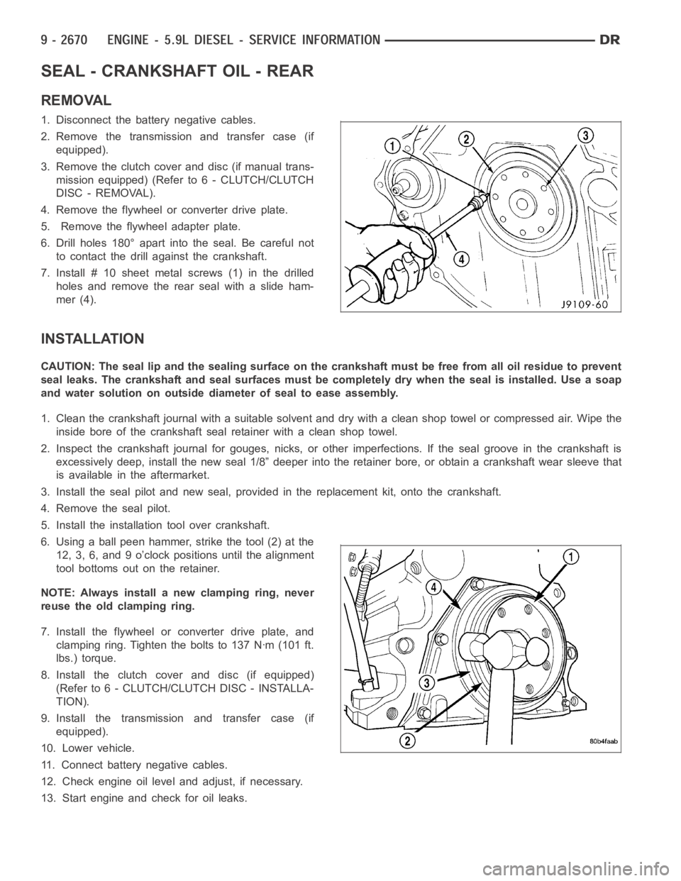
6. Drill holes 180° apart into the seal. Be careful not
to contact the drill against the crankshaft.
7. Install # 10 sheet metalscrews (1) in the drilled
holes and remove the rear seal with a slide ham-
mer (4).
INSTALLATION
CAUTION: The seal lip and the sealing surface on the crankshaft must be freefrom all oil residue to prevent
seal leaks. The crankshaft and seal surfaces must be completely dry when the seal is installed. Use a soap
and water solution on outside diameter of seal to ease assembly.
1. Clean the crankshaft journal with a suitable solvent and dry with a cleanshop towel or compressed air. Wipe the
inside bore of the crankshaft seal retainer with a clean shop towel.
2. Inspect the crankshaft journal forgouges, nicks, or other imperfections. If the seal groove in the crankshaft is
excessively deep, install the new seal 1/8” deeper into the retainer bore,or obtain a crankshaft wear sleeve that
is available in the aftermarket.
3. Install the seal pilot and new seal, provided in the replacement kit, onto the crankshaft.
4. Remove the seal pilot.
5. Install the installation tool over crankshaft.
6. Using a ball peen hammer, strike the tool (2) at the
12, 3, 6, and 9 o’clock positions until the alignment
tool bottoms out on the retainer.
NOTE: Always install a new clamping ring, never
reuse the old clamping ring.
7. Install the flywheel or converter drive plate, and
clamping ring. Tighten the bolts to 137 Nꞏm (101 ft.
lbs.) torque.
8. Install the clutch cover and disc (if equipped)
(Refer to 6 - CLUTCH/CLUTCH DISC - INSTALLA-
TION).
9. Install the transmission and transfer case (if
equipped).
10. Lower vehicle.
11. Connect battery negative cables.
12. Check engine oil level and adjust, if necessary.
13. Start engine and check for oil leaks.