2006 DODGE RAM SRT-10 tow
[x] Cancel search: towPage 2657 of 5267
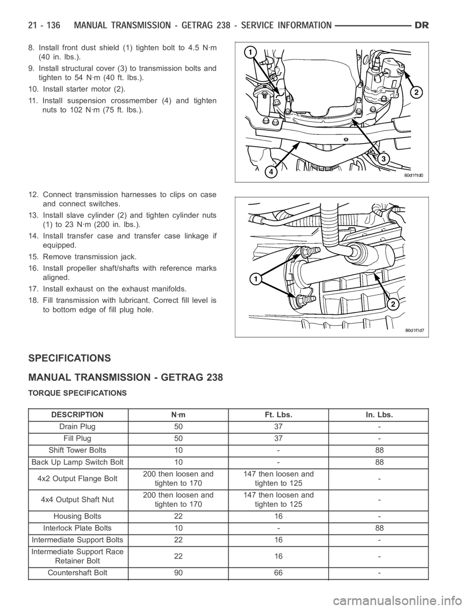
8. Install front dust shield (1) tighten bolt to 4.5 Nꞏm
(40 in. lbs.).
9. Install structural cover (3) to transmission bolts and
tighten to 54 Nꞏm (40 ft. lbs.).
10. Install starter motor (2).
11. Install suspension crossmember (4) and tighten
nuts to 102 Nꞏm (75 ft. lbs.).
12. Connect transmission harnesses to clips on case
and connect switches.
13. Install slave cylinder (2) and tighten cylinder nuts
(1)to23Nꞏm(200in.lbs.).
14. Install transfer case and transfer case linkage if
equipped.
15. Remove transmission jack.
16. Install propeller shaft/shafts with reference marks
aligned.
17. Install exhaust on the exhaust manifolds.
18. Fill transmission with lubricant. Correct fill level is
to bottom edge of fill plug hole.
SPECIFICATIONS
MANUAL TRANSMISSION - GETRAG 238
TORQUE SPECIFICATIONS
DESCRIPTION Nꞏm Ft. Lbs. In. Lbs.
Drain Plug 50 37 -
Fill Plug 50 37 -
Shift Tower Bolts 10 - 88
Back Up Lamp Switch Bolt 10 - 88
4x2 Output Flange Bolt200 then loosen and
tighten to 170147 then loosen and
tighten to 125-
4x4 Output Shaft Nut200 then loosen and
tighten to 170147 then loosen and
tighten to 125-
Housing Bolts 22 16 -
Interlock Plate Bolts 10 - 88
Intermediate Support Bolts 22 16 -
Intermediate Support Race
Retainer Bolt22 16 -
Countershaft Bolt 90 66 -
Page 2689 of 5267
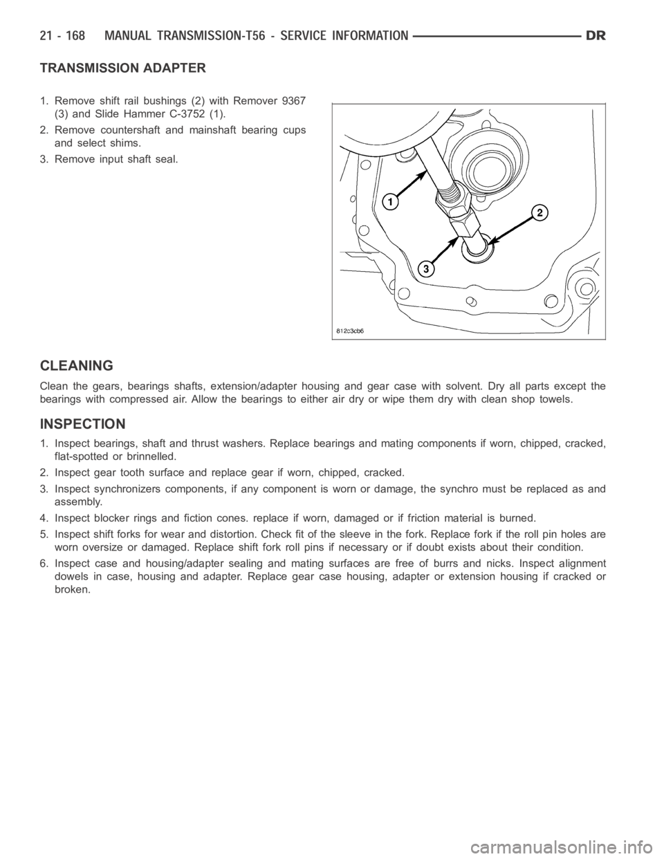
TRANSMISSION ADAPTER
1. Remove shift rail bushings (2) with Remover 9367
(3) and Slide Hammer C-3752 (1).
2. Remove countershaft and mainshaft bearing cups
and select shims.
3. Remove input shaft seal.
CLEANING
Clean the gears, bearings shafts, extension/adapter housing and gear case with solvent. Dry all parts except the
bearings with compressed air. Allow the bearings to either air dry or wipe them dry with clean shop towels.
INSPECTION
1. Inspect bearings, shaft and thrust washers. Replace bearings and mating components if worn, chipped, cracked,
flat-spotted or brinnelled.
2. Inspect gear tooth surface and replace gear if worn, chipped, cracked.
3. Inspect synchronizers components, if any component is worn or damage, the synchro must be replaced as and
assembly.
4. Inspect blocker rings and fiction cones. replace if worn, damaged or if friction material is burned.
5. Inspect shift forks for wear and distortion. Check fit of the sleeve in the fork. Replace fork if the roll pin holes are
worn oversize or damaged. Replace shift fork roll pins if necessary or if doubt exists about their condition.
6. Inspect case and housing/adapter sealing and mating surfaces are free of burrs and nicks. Inspect alignment
dowels in case, housing and adapter. Replace gear case housing, adapter orextension housing if cracked or
broken.
Page 2711 of 5267
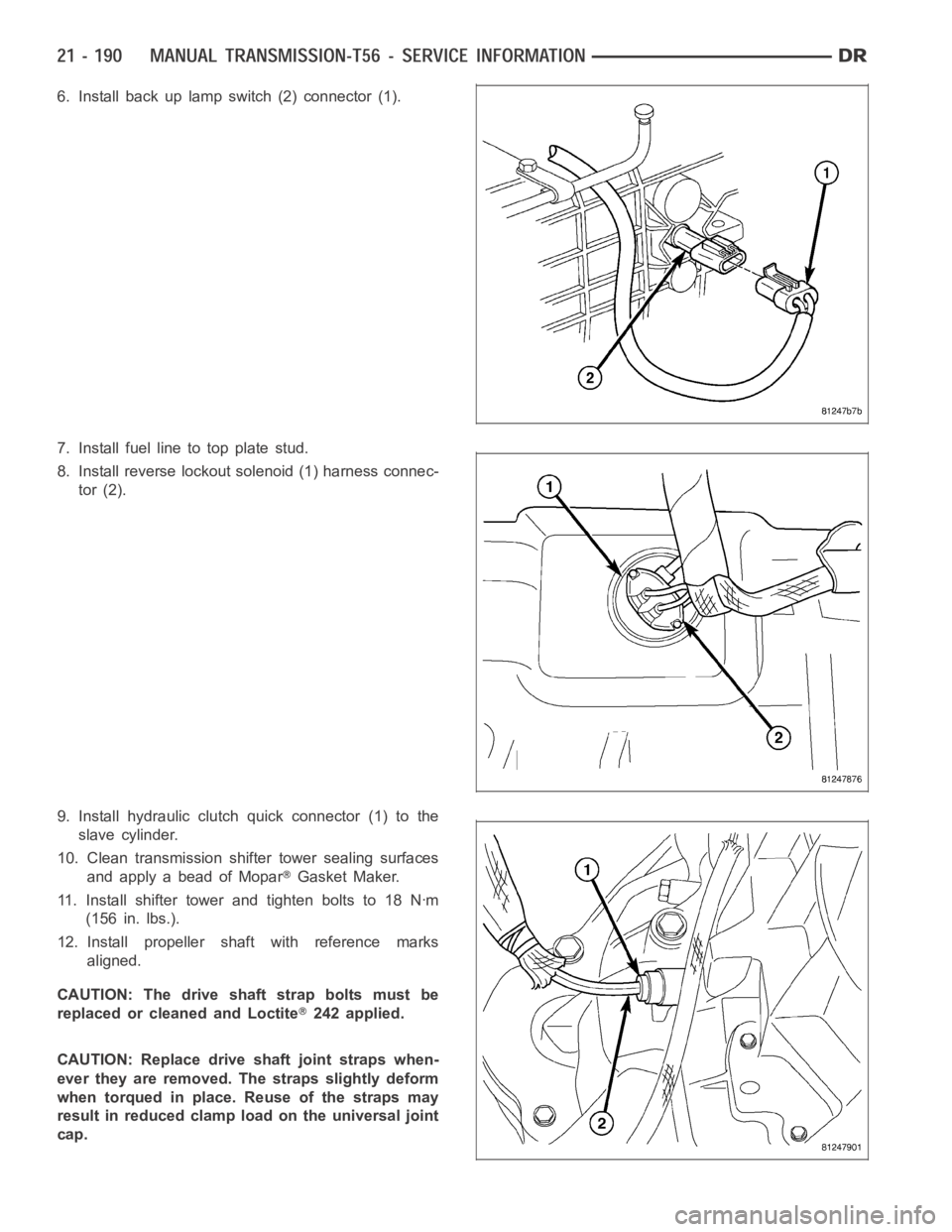
6. Install back up lamp switch (2) connector (1).
7. Install fuel line to top plate stud.
8. Install reverse lockout solenoid (1) harness connec-
tor (2).
9. Install hydraulic clutch quick connector (1) to the
slave cylinder.
10. Clean transmission shifter tower sealing surfaces
and apply a bead of Mopar
Gasket Maker.
11. Install shifter tower and tighten bolts to 18 Nꞏm
(156 in. lbs.).
12. Install propeller shaft with reference marks
aligned.
CAUTION: The drive shaft strap bolts must be
replaced or cleaned and Loctite
242 applied.
CAUTION: Replace drive shaft joint straps when-
ever they are removed. The straps slightly deform
when torqued in place. Reuse of the straps may
result in reduced clamp load on the universal joint
cap.
Page 2732 of 5267
P0218-HIGH TEMPERATURE OPERATION ACTIVATED
For a complete wiring diagramRefer to Section 8W.
When Monitored:
Whenever the engine is running.
Set Condition:
Immediately when a Overheat shift schedule is activated when the Transmission Oil Temperature reaches 155°
C or 240° F.
Possible Causes
ENGINE COOLING SYSTEM OPERATION
TRANSMISSION OIL COOLER PLUGGED
H I G H T E M P E R AT U R E O P E R AT I O N S A C T I VAT E D
Always perform the Pre-Diagnostic Troubleshooting procedure before proceeding. (Refer to 21 - TRANSMIS-
SION/TRANSAXLE/AUTOMATIC - 42RLE - STANDARD PROCEDURE)
Theory of Operation
If the transmission oil temperature rises above 115° C (240° F), the overheat shift schedule is activated refer to
Transmission Operation as a function of Transmission Oil Temperature andthe code is set. The DTC is an infor-
mational code only and is being set to aid the technician in determining root cause of a customer driveability issue.
The code is also intended to alert the technician to determine if a cooling system malfunction has occurred or if an
additional transmission air to oil cooler should be added to the vehicle ifthe customer regularly drives in a manner
that overheats the transmission. Extended operation above 115° C (240° F)will reduce the durability of the trans-
mission and should be avoided. Correcting the cooling system malfunctionor installing an additional transmission oil
cooler will improve transmission durability especially for customers who operate in city/construction stop and go traf-
fic, tow trailers regularly, drive aggressively in low gear or drive regularly in mountainous areas.
Diagnostic Test
1.CHECK ENGINE COOLING SYSTEM
Perform Engine Cooling System diagnostics per the Service Information.
Is the Engine Cooling System functioning properly?
Ye s>>
Go To 2
No>>
Repair the cause of the engine overheating. Refer to the Service Information for the related diagnostic
or repair procedures.
Perform 42RLE TRANSMISSION VERIFICATION TEST - VER 1. (Refer to 21 - TRANSMISSION/
TRANSAXLE/AUTOMATIC - 42RLE - STANDARD PROCEDURE)
2.TRANSMISSION OIL COOLER RESTRICTED
Check the Transmission Oil Cooler Flow in accordance with the Service Information.
Is the transmission oil cooler restricted or plugged?
Ye s>>
Go To 3
No>>
Repair the cause of the plugged Transmission Oil Cooler as necessary and repair or replace the Trans-
mission Oil Cooler per the Service Information.
Perform 42RLE TRANSMISSION VERIFICATION TEST - VER 1. (Refer to 21 - TRANSMISSION/
TRANSAXLE/AUTOMATIC - 42RLE - STANDARD PROCEDURE)
Page 2744 of 5267
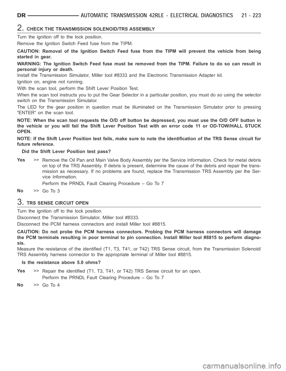
2.CHECK THE TRANSMISSION SOLENOID/TRS ASSEMBLY
Turn the ignition off to the lock position.
Remove the Ignition Switch Feed fuse from the TIPM.
CAUTION: Removal of the Ignition Switch Feed fuse from the TIPM will prevent the vehicle from being
startedingear.
WARNING: The Ignition Switch Feed fuse must be removed from the TIPM. Failure to do so can result in
personal injury or death.
Install the Transmission Simulator,Miller tool #8333 and the ElectronicTransmission Adapter kit.
Ignition on, engine not running.
With the scan tool, perform the Shift Lever Position Test.
When the scan tool instructs you to put the Gear Selector in a particular position, you must do so using the selector
switch on the Transmission Simulator.
The LED for the gear position in question must be illuminated on the Transmission Simulator prior to pressing
ENTERon the scan tool.
NOTE: When the scan tool requests the O/D off button be depressed, you must use the O/D OFF button in
the vehicle or you will fail the Shift Lever Position Test with an error code11 or OD-TOW/HALL STUCK
OPEN.
NOTE: If the Shift Lever Position test fails, make sure to note the identification of the TRS Sense circuit for
future reference.
Did the Shift Lever Position test pass?
Ye s>>
Remove the Oil Pan and Main Valve Body Assembly per the Service Information. Check for metal debris
on top of the TRS Assembly. If debris is present, determine the cause of the debris and repair the trans-
mission as necessary. If no problems are found, replace the Transmission TRS Assembly per the Ser-
vice Information.
Perform the PRNDL Fault Clearing Procedure – Go To 7
No>>
Go To 3
3.TRS SENSE CIRCUIT OPEN
Turn the ignition off to the lock position.
Disconnect the Transmission Simulator, Miller tool #8333.
Disconnect the PCM harness connectors and install Miller tool #8815.
CAUTION: Do not probe the PCM harness connectors. Probing the PCM harness connectors will damage
the PCM terminals resulting in poor terminal to pin connection. Install Miller tool #8815 to perform diagno-
sis.
Measure the resistance of the identified (T1, T3, T41, or T42) TRS Sense circuit, from the Transmission Solenoid/
TRS Assembly harness connector to theappropriate terminal of Miller tool#8815.
Is the resistance above 5.0 ohms?
Ye s>>
Repair the identified (T1, T3, T41, or T42) TRS Sense circuit for an open.
Perform the PRNDL Fault Clearing Procedure – Go To 7
No>>
Go To 4
Page 2864 of 5267
P0944-LOSS OF HYDRAULIC PUMP PRIME
For a complete wiring diagramRefer to Section 8W.
When Monitored:
Every 350 msec
Set Condition:
If the transmission begins to slip in any forward gear, and the pressure switch or switches that should be
closed for a given gear are open, a loss of prime test begins. All available elements (in 1st gear LR, 2/4 and
OD, in 2nd, 3rd, and 4th gear 2/4 and OD) are turned on by the PCM to see if pump prime exists. The code
is set if none of the pressure switches respond. The PCM will continue to runthe loss of prime test until pump
pressure returns. The vehicle will not move or the transmission will slip.Normal operation will continue if pump
prime returns.
Possible Causes
LOW TRANSMISSION FLUID LEVEL
SHIFT LEVER POSITION
PLUGGED TRANSMISSION FILTER
TRANSMISSION OIL PUMP
Always perform the 42RLE Pre-Diagnostic Troubleshooting procedure before proceeding. (Refer to 21 -
TRANSMISSION/TRANSAXLE/AUTOMATIC - 42RLE - STANDARD PROCEDURE)
Theory of Operation
The Loss of Prime Test is used to prevent transmission defaults and erroneous fault codes during temporary loss of
pump prime that may occur with low transmission fluid under severe brakingconditions, start-up, etc. and to point
towards more subtle problems such as a plugged or ruptured oil filter. The Loss of Prime fault is set by a loss of
hydraulic pressure in the transmission system. This condition, if sustained, will result in the vehicle being unable to
move.
Diagnostic Test
1.CHECK TO SEE IF DTC P0944 IS CURRENT
Place the gear selector in park.
Start the engine.
NOTE: The Transmission Temperature must be at least 43° C (110° F) before performing the following steps.
The Transmission must be at operating temperature prior to checking pressure. Cold transmission fluid will result in
higher pressure readings.
Place the Transmission in Reverse.
With the scan tool, observe the Transmission Pressure Switch states.
Are any of the Pressure Switches closed?
Ye s>>
Go To 2
No>>
Go To 4
Page 2883 of 5267
P1713-RESTRICTED MANUAL VALVE IN T2 RANGE
For a complete wiring diagramRefer to Section 8W
When Monitored:
Ignition on, engine running with the gear shift selector in a valid forwardgear.
Set Condition:
This DTC sets whenever Transmission control system detects the manual valve is in the T2 range when it
should be in OD. This is mainly an informational DTC.
Possible Causes
RELATED TRANSMISSION DTC’S PRESENT
CUSTOMER DRIVING HABITS
MIS-ADJUSTED SHIFTER CABLE
Always perform the Pre-Diagnostic Troubleshooting procedure before proceeding. (Refer to 21 - TRANSMIS-
SION/TRANSAXLE/AUTOMATIC - 42RLE - STANDARD PROCEDURE)
Diagnostic Test
1.DETERMINING IF RELATED DTC’S ARE PRESENT
With the scan tool, check for other transmission DTC’s
Are there any speed sensor or gear ratio DTCs present?
Ye s>>
Refer to the Transmission category and perform the appropriate symptom.
No>>
Go To 2
2.CHECK THE GEAR SHIFT CABLE FOR PROPER ADJUSTMENT
Check the Gear shift cable adjustment per the Service Information.
Also check the cable for possible binding or improperly routed.
Is the Gear shift cable properly adjusted and not binding or improperly routed?
Ye s>>
Go To 3
No>>
Adjust the Shifter Assembly per the Service Information.
Perform 42RLE TRANSMISSION VERIFICATION TEST - VER 1. (Refer to 21 - TRANSMISSION/
TRANSAXLE/AUTOMATIC - 42RLE - STANDARD PROCEDURE)
3.CHECK CUSTOMER DRIVING HABIT
This DTC can be set if the customer does not move the shift lever completely into the OD position (in between
gears) causing the manual valve to be in the T2 position.
When this occurs, the feed port to the clutch is restricted, the transmission will declare neutral, and this DTC will
set.
This DTC can also be set by simply bumping the shift lever toward neutral while accelerating.
With the scan tool, check the DTC EVENT DATA to help identify the conditionsin which the DTC was set.
If there are no possible causes remaining, view repair.
Repair
This DTC can be set by the shift lever inthe wrong position or not completelyin the OD position. Make
sure the customer is properly informed.
Perform 42RLE TRANSMISSION VERIFICATION TEST - VER 1. (Refer to 21 - TRANSMISSION/
TRANSAXLE/AUTOMATIC - 42RLE - STANDARD PROCEDURE)
Page 2899 of 5267
P1797-MANUAL SHIFT OVERHEAT
For a complete wiring diagramRefer to Section 8W.
When Monitored:
Continuously with engine running.
Set Condition:
If the Engine Temperature exceeds 123° C (255° F) or the Transmission Temperature exceeds 135° C (275° F)
while in AutoStick
mode. Note: Aggressive driving or driving in low for extended periods of time will set this
DTC.
Possible Causes
MANUAL SHIFT OVERHEAT
Always perform the 42RLE Pre-Diagnostic Troubleshooting procedure before proceeding. (Refer to 21 -
TRANSMISSION/TRANSAXLE/AUTOMATIC - 42RLE - STANDARD PROCEDURE)
Theory of Operation
The major cause of heat build up in the transmission is torque converter slip.WiththetransmissionintheAuto-
Stick
mode, the torque converter can slip during aggressive driving or heavy loading conditions such as trailer
towing or driving up steep grades. In the non AutoStick
mode, internal controller logic prevents the transmission
from overheating by managing the shift and EMCC schedule. In the AutoStick
mode, when the transmission or
engine temperature approaches an overheat condition, the manual shift overheat DTC sets and the AutoStick
mode is temporarily suspended until the temperature returns to normal.
Diagnostic Test
1.MANUAL SHIFT OVERHEAT
This is an informational DTC only.
With the scan tool, check the DTC EVENT DATA to help identify the conditionsin which the DTC was set.
Check the engine and transmission cooling system for proper operation.
Check the Radiator Cooling Fan operation.
Check the Transmission Cooling operation.
Check the Transmission Fluid Level per the Service Information to verify that it is not overfilled.
NOTE: Aggressive driving or driving in low for extended periods of time will set this DTC.
If there are no possible causes remaining, view repair.
Repair
If the Transmission Fluid is low, repair any Transmission Fluid leak as necessary and adjust the Trans-
mission Fluid Level per the Service Information. Refer to Service Information for the related symptoms
and repair as necessary.
Perform 42RLE TRANSMISSION VERIFICATION TEST - VER 1. (Refer to 21 - TRANSMISSION/
TRANSAXLE/AUTOMATIC - 42RLE - STANDARD PROCEDURE)