Page 2333 of 5267

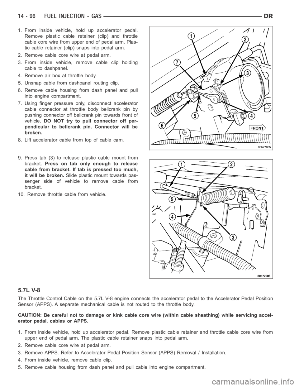
1. From inside vehicle, hold up accelerator pedal.
Remove plastic cable retainer (clip) and throttle
cable core wire from upper end of pedal arm. Plas-
tic cable retainer (clip) snaps into pedal arm.
2. Remove cable core wire at pedal arm.
3. From inside vehicle, remove cable clip holding
cable to dashpanel.
4. Remove air box at throttle body.
5. Unsnap cable from dashpanel routing clip.
6. Remove cable housing from dash panel and pull
into engine compartment.
7. Using finger pressure only, disconnect accelerator
cable connector at throttle body bellcrank pin by
pushing connector off bellcrank pin towards front of
vehicle.DO NOT try to pull connector off per-
pendicular to bellcrank pin. Connector will be
broken.
8. Lift accelerator cable from top of cable cam.
9. Press tab (3) to release plastic cable mount from
bracket.Press on tab only enough to release
cable from bracket. If tab is pressed too much,
it will be broken.Slide plastic mount towards pas-
senger side of vehicle to remove cable from
bracket.
10. Remove throttle cable from vehicle.
5.7L V-8
The Throttle Control Cable on the 5.7L V-8 engine connects the acceleratorpedal to the Accelerator Pedal Position
Sensor (APPS). A separate mechanical cable is not routed to the throttle body.
CAUTION: Be careful not to damage or kink cable core wire (within cable sheathing) while servicing accel-
erator pedal, cables or APPS.
1. From inside vehicle, hold up accelerator pedal. Remove plastic cable retainer and throttle cable core wire from
upper end of pedal arm. The plastic cable retainer snaps into pedal arm.
2. Remove cable core wire at pedal arm.
3. Remove APPS. Refer to Accelerator Pedal Position Sensor (APPS) Removal/ Installation.
4. From inside vehicle, remove cable clip.
5. Remove cable housing from dash panel and pull cable into engine compartment.
Page 2363 of 5267

REMOVAL
CAUTION: Cleanliness cannot be overemphasized when handling or replacingdieselfuelsystemcompo-
nents. This especially includes the fuel injectors, high-pressure fuel lines and fuel injection pump. Very tight
tolerances are used with these parts. Dirt contamination could cause rapid part wear and possible plugging
of fuel injector nozzle tip holes. This in turn could lead to possible engine misfire. Always wash/clean any
fuel system component thoroughly before disassembly and then air dry. Capor cover any open part after
disassembly. Before assembly, examine each part for dirt, grease or othercontaminants and clean if nec-
essary. When installing new parts, lubricate them with clean engine oil orclean diesel fuel only.
1. Disconnect both negative battery cables from both
batteries. Cover and isolate ends of cables.
2. Thoroughly clean fuel lines at both ends.
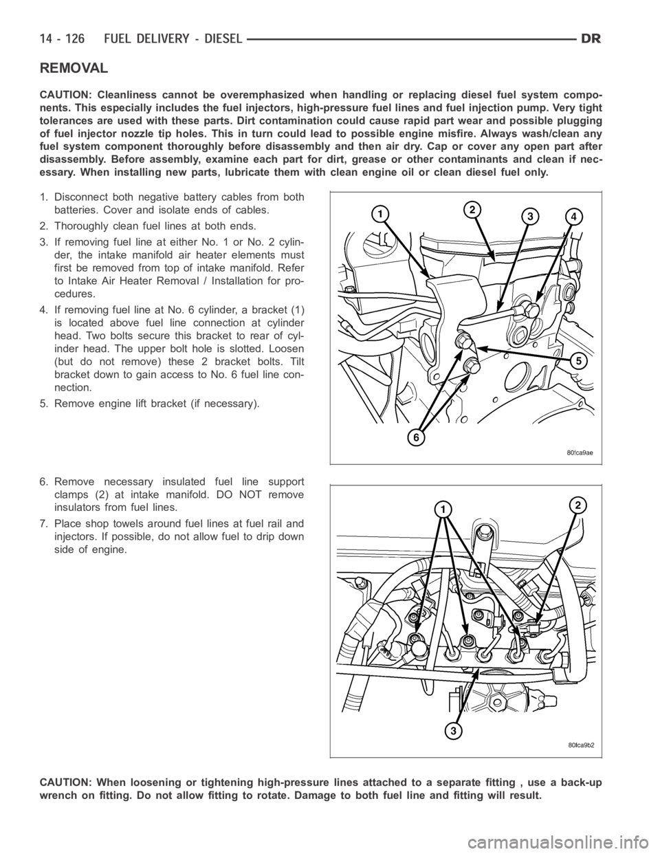
3. If removing fuel line at either No. 1 or No. 2 cylin-
der, the intake manifold air heater elements must
first be removed from top of intake manifold. Refer
to Intake Air Heater Removal / Installation for pro-
cedures.
4. If removing fuel line at No. 6 cylinder, a bracket (1)
is located above fuel line connection at cylinder
head. Two bolts secure this bracket to rear of cyl-
inder head. The upper bolt hole is slotted. Loosen
(but do not remove) these 2 bracket bolts. Tilt
bracket down to gain access to No. 6 fuel line con-
nection.
5. Remove engine lift bracket (if necessary).
6. Remove necessary insulated fuel line support
clamps (2) at intake manifold. DO NOT remove
insulators from fuel lines.
7. Place shop towels around fuel lines at fuel rail and
injectors. If possible, do not allow fuel to drip down
side of engine.
CAUTION: When loosening or tightening high-pressure lines attached to a separate fitting , use a back-up
wrench on fitting. Do not allow fitting to rotate. Damage to both fuel line and fitting will result.
Page 2434 of 5267
7. Remove the blocker pin (1) from the inhibit link slot
(2) and remove the lever (3) by pulling forward
toward the steering wheel and to the left then
down.
INSTALLATION
1. Install the lever assembly (3) reversing the way it
came out using care to install the pin (2) in the
blocker to slider slot (1).
Page 2494 of 5267

SWITCH-POWER STEERING PRESSURE
DESCRIPTION
A pressure sensing switch is used in the power steering system. It is mounted on the high-pressure steering hose.
This switch will only be used onHD vehicleswith the 5.7L engines. There is no pressure switch used for the 3.7L,
4.7L, 5.9LDiesel engine or the5.7L LD vehiclepump.
OPERATION
The switch is used on the 5.7L V-8 enginesHD vehicles only.
The power steering pressure switch provides an input to the Powertrain Control Module (PCM). This input is pro-
vided during periods of high steering pump load and low engine rpm; such as during parking maneuvers. The PCM
increases the idle speed through the Idle Air Control (IAC) motor. This is done to prevent the engine from stalling
under the increased load.
When steering pump pressure exceeds 3275 kPa ± 690 kPa (475 psi ± 100 psi), the Normally Closed (NC) switch
will open and the PCM will increase the engine idle speed. This will preventthe engine from stalling.
When pump pressure drops to approximately 1379 kPa (200 psi), the switch circuit will re-close and engine idle
speed will return to its previous setting.
REMOVAL - 5.7L - HD VEHICLES ONLY
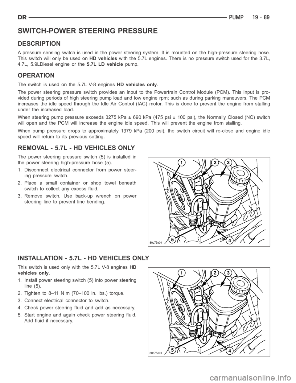
The power steering pressureswitch (5) is installed in
the power steering high-pressure hose (5).
1. Disconnect electrical connector from power steer-
ing pressure switch.
2. Place a small container or shop towel beneath
switch to collect any excess fluid.
3. Remove switch. Use back-up wrench on power
steering line to prevent line bending.
INSTALLATION - 5.7L - HD VEHICLES ONLY
This switch is used only with the 5.7L V-8 enginesHD
vehicles only.
1. Install power steering switch (5) into power steering
line (5).
2. Tighten to 8–11 Nꞏm (70–100 in. lbs.) torque.
3. Connect electrical connector to switch.
4. Check power steering fluid and add as necessary.
5. Start engine and again check power steering fluid.
Add fluid if necessary.
Page 2512 of 5267
RETURN HOSE - FAN TO PUMP
NOTE: Before installing power steering hose, clean open power steering hose ends and fittings with a lint-
free towel.
1. Slide hose clamps onto ends of return hose far enough to clear molded fitting on pump reservoir and fan fitting
once hose is installed.
2. Slidefanendofreturnhose(9)ontofanfluidfitting.Expandhoseclampandslideitintopositiononhosepast
bead formed into fitting.
3. Install power steering pressure hose into routing clip (7) on cooling module (5).
4. Slide pump end of return hose (9) onto molded fitting on pump reservoir (3). Expand hose clamp and slide it into
position on hose past bead formed into reservoir fitting.
5. Fill power steering pump reservoir to correct fluid level. (Refer to 19 -STEERING/PUMP/FLUID - STANDARD
PROCEDURE)
6. Perform Power Steering Pump Initial Operation procedure. (Refer to 19 -STEERING/PUMP - STANDARD PRO-
CEDURE).
7. Check for leaks at all hose connections.
Page 2525 of 5267
REMOVAL
1. With vehicle in neutral, position vehicle on hoist.
2. Disconnect battery negative cable.
3. Remove shift boot bezel screws and slide boot
upward on shift lever extension.
4. Remove shift lever extension from the shift tower
and lever assembly.
5. Remove 4WD shift boot if equipped.
6. Remove skid plate, if equipped.
7. Remove drain plug (1) from transmission (2) and
drain fluid.
8. Mark transmission flange (1) and propeller shaft (2)
for installation reference before removing propeller
shaft. If 4x4 equipped mark transfer case and front
propeller shaft before removing shaft.
Page 2529 of 5267
DISASSEMBLY
1. Set transmission on rear housing.
2. Remove shift tower bolts (1) and shift tower (2).
3. Pry off shift tower boot (1) with a screw driver (2).
Page 2530 of 5267
4. Through the shift tower opening (1) align shift rails
(2) and install tie strap to shift rails.
5. Remove 5-6 shift fork pivot pin (1) from both sides
of the case.
6. Remove reverse idler gear shaft pin (1) from the
rear housing (2).