2006 DODGE RAM SRT-10 tow
[x] Cancel search: towPage 2032 of 5267
material also will prevent corrosion. MoparGasket Sealant is available in a 13 oz. aerosol can or 4 oz./16 oz. can
w/applicator.
FORM-IN-PLACE GASKET AND SEALER APPLICATION
MoparGasket Maker material should be applied sparingly 1 mm (0.040 in.) diameter or less of sealant to one
gasket surface. Be certain the material surrounds each mounting hole. Excess material can easily be wiped off.
Components should be torqued in place within 15 minutes. The use of a locating dowel is recommended during
assembly to prevent smearing material off the location.
Mopar
Engine RTV GEN II or ATF RTV gasket material should be applied in a continuous bead approximately 3
mm (0.120 in.) in diameter. All mounting holes must be circled. For corner sealing,a3.17mmor6.35mm(1/8in.
or 1/4 in.) drop is placed in the center of the gasket contact area. Uncured sealant may be removed with a shop
towel. Components should be torqued in place while the sealant is still wettothetouch(within10minutes).The
usage of a locating dowel is recommended during assembly to prevent smearing material off the location.
Mopar
Gasket Sealant in an aerosol can should be applied using a thin, even coat sprayed completely over both
surfaces to be joined, and both sides of a gasket. Then proceed with assembly. Material in a can w/applicator can
be brushed on evenly over the sealing surfaces. Material in an aerosol can shouldbeusedonengineswithmulti-
layer steel gaskets.
ENGINE GASKET SURFACE PREPARATION
To ensure engine gasket sealing, proper surface prep-
aration must be performed, especially with the use of
aluminum engine components and multi-layer steel
cylinder head gaskets.
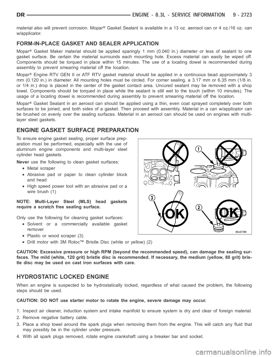
Neveruse the following to clean gasket surfaces:
Metal scraper
Abrasive pad or paper to clean cylinder block
and head
High speed power tool with an abrasive pad or a
wire brush (1)
NOTE: Multi-Layer Steel (MLS) head gaskets
require a scratch free sealing surface.
Only use the following for cleaning gasket surfaces:
Solvent or a commercially available gasket
remover
Plastic or wood scraper (3)
Drill motor with 3M Roloc™ Bristle Disc (white or yellow) (2)
CAUTION: Excessive pressure or high RPM (beyond the recommended speed), can damage the sealing sur-
faces. The mild (white, 120 grit) bristle disc is recommended. If necessary, the medium (yellow, 80 grit) bris-
tle disc may be used on cast iron surfaces with care.
HYDROSTATIC LOCKED ENGINE
When an engine is suspected to be hydrostatically locked, regardless of what caused the problem, the following
steps should be used.
CAUTION: DO NOT use starter motor to rotate the engine, severe damage may occur.
1. Inspect air cleaner, induction system and intake manifold to ensure system is dry and clear of foreign material.
2. Remove negative battery cable.
3. Place a shop towel around the spark plugs when removing them from the engine. This will catch any fluid that
may possibly be in the cylinder under pressure.
4. With all spark plugs removed, rotate engine crankshaft using a breaker bar and socket.
Page 2058 of 5267
6. Disconnect brake booster vacuum hose from the
intake manifold and set aside.
WARNING: WRAP A SHOP TOWEL AROUND FUEL
LINE TO CATCH ANY GASOLINE SPILLAGE.
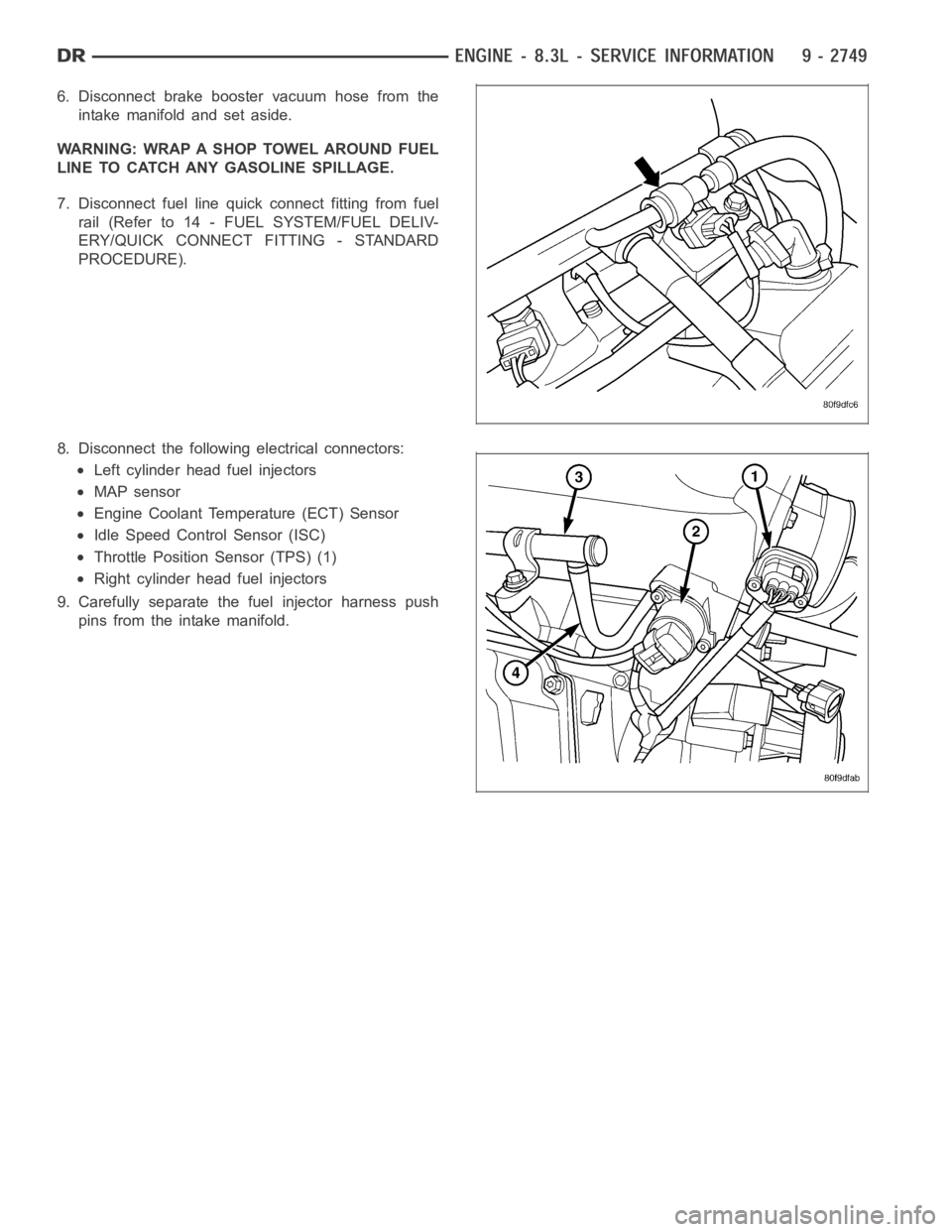
7. Disconnect fuel line quick connect fitting from fuel
rail (Refer to 14 - FUEL SYSTEM/FUEL DELIV-
ERY/QUICK CONNECT FITTING - STANDARD
PROCEDURE).
8. Disconnect the following electrical connectors:
Left cylinder head fuel injectors
MAP sensor
Engine Coolant Temperature (ECT) Sensor
Idle Speed Control Sensor (ISC)
Throttle Position Sensor (TPS) (1)
Right cylinder head fuel injectors
9. Carefully separate the fuel injector harness push
pins from the intake manifold.
Page 2072 of 5267
SPRINGS/SEALS-VALVE
DIAGNOSIS AND TESTING
VA LV E S P R I N G T E S T I N G
The valve springs should be tested whenever
removed for inspection, reconditioning, or replace-
ment.
1. Obtain specifications for spring tension at specified
spring length (Refer to 9 - ENGINE - SPECIFICA-
TIONS).
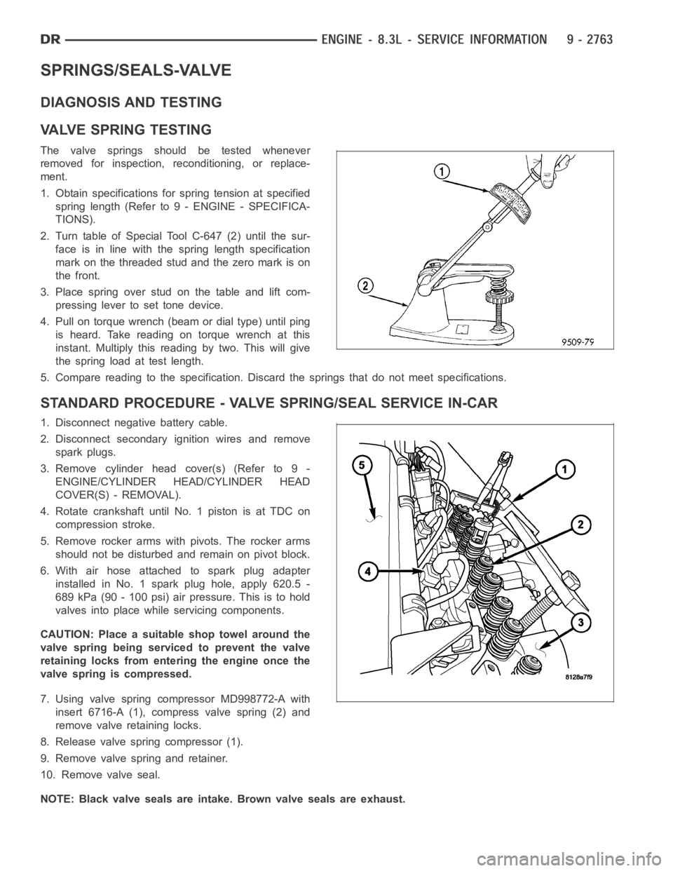
2. Turn table of Special Tool C-647 (2) until the sur-
face is in line with the spring length specification
mark on the threaded stud and the zero mark is on
the front.
3.Placespringoverstudonthetableandliftcom-
pressing lever to set tone device.
4. Pull on torque wrench (beam or dial type) until ping
is heard. Take reading on torque wrench at this
instant. Multiply this reading by two. This will give
the spring load at test length.
5. Compare reading to the specification. Discard the springs that do not meet specifications.
STANDARD PROCEDURE - VALVE SPRING/SEAL SERVICE IN-CAR
1. Disconnect negative battery cable.
2. Disconnect secondary ignition wires and remove
spark plugs.
3. Remove cylinder head cover(s) (Refer to 9 -
ENGINE/CYLINDER HEAD/CYLINDER HEAD
COVER(S) - REMOVAL).
4. Rotate crankshaft until No. 1 piston is at TDC on
compression stroke.
5. Remove rocker arms with pivots. The rocker arms
should not be disturbed and remain on pivot block.
6. With air hose attached to spark plug adapter
installed in No. 1 spark plug hole, apply 620.5 -
689 kPa (90 - 100 psi) air pressure. This is to hold
valves into place while servicing components.
CAUTION: Place a suitable shop towel around the
valve spring being serviced to prevent the valve
retaining locks from entering the engine once the
valve spring is compressed.
7. Using valve spring compressor MD998772-A with
insert 6716-A (1), compress valve spring (2) and
remove valve retaining locks.
8. Release valve spring compressor (1).
9. Remove valve spring and retainer.
10. Remove valve seal.
NOTE: Black valve seals are intake. Brown valve seals are exhaust.
Page 2104 of 5267
BLOCK-ENGINE
DESCRIPTION
The cylinder block is made of a sand-cast aluminum alloy. The cylinder block has interference-fit cast iron cylinder
liners. The cylinder liners are thermally installed during block manufacturing; they are not serviceable items.
Six iron main bearing caps use four bolts per cap; two vertical and two horizontal. A crankshaft oil scraper is
attached to the main bearing caps via extended main bearing cap bolts and nuts.
STANDARD PROCEDURE - CYLINDER BORE HONING
Before honing, stuff plenty of clean shop towels under
the bores and over the crankshaft to keep abrasive
materials from entering the crankshaft area.
1. Used carefully, the Cylinder Bore Sizing Hone
C-823, equipped with 220 grit stones, is the best
tool for this job. In addition to deglazing, it will
reduce taper and out-of-round, as well as removing
light scuffing, scoring and scratches. Usually, a few
strokes will clean up a bore and maintain the
required limits.
CAUTION: DO NOT use rigid type hones to remove
cylinder wall glaze.
2. Deglazing of the cylinder walls may be done if the
cylinder bore is straight and round. Use a cylinder
surfacing hone, Honing Tool C-3501, equipped with
280 grit stones (C-3501-3810). about 20-60
strokes, depending on the bore condition, will be
sufficient to provide a satisfactory surface. Using
honing oil C-3501-3880, or a light honing oil, avail-
able from major oil distributors.
CAUTION: DO NOT use engine or transmission oil, mineral spirits, or kerosene.
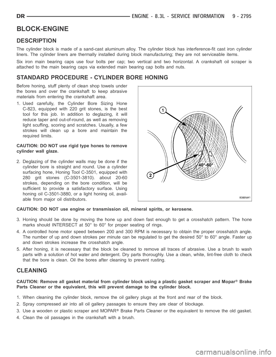
3. Honing should be done by moving the hone up and down fast enough to get a crosshatch pattern. The hone
marks should INTERSECT at 50° to 60° for proper seating of rings.
4. A controlled hone motor speed between 200 and 300 RPM is necessary to obtain the proper crosshatch angle.
The number of up and down strokes per minute can be regulated to get the desired 50° to 60° angle. Faster up
and down strokes increase the crosshatch angle.
5. After honing, it is necessary that the block be cleaned to remove all traces of abrasive. Use a brush to wash
parts with a solution of hot water and detergent. Dry parts thoroughly. Usea clean, white, lint-free cloth to check
that the bore is clean. Oil the bores after cleaning to prevent rusting.
CLEANING
CAUTION: Remove all gasket material from cylinder block using a plastic gasket scraper and MoparBrake
Parts Cleaner or the equivalent, this will prevent damage to the cylinder block.
1. When cleaning the cylinder block, remove the oil gallery plugs at the front and rear of the block.
2. Spray compressed air into all oil gallery passages to ensure they are clear of blockage.
3. Use a wooden or plastic scraper and MOPAR
Brake Parts Cleaner or the equivalent to remove the old gasket.
4. Clean the oil passages in the crankshaft with a brush.
Page 2107 of 5267
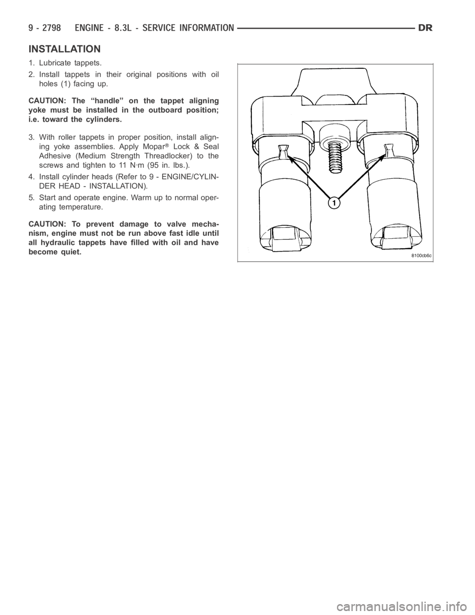
INSTALLATION
1. Lubricate tappets.
2. Install tappets in their original positions with oil
holes (1) facing up.
CAUTION: The “handle” on the tappet aligning
yoke must be installed in the outboard position;
i.e. toward the cylinders.
3. With roller tappets in proper position, install align-
ing yoke assemblies. Apply Mopar
Lock & Seal
Adhesive (Medium Strength Threadlocker) to the
screwsandtightento11Nꞏm(95in.lbs.).
4. Install cylinder heads (Refer to 9 - ENGINE/CYLIN-
DER HEAD - INSTALLATION).
5. Start and operate engine. Warm up to normal oper-
ating temperature.
CAUTION: To prevent damage to valve mecha-
nism, engine must not be run above fast idle until
all hydraulic tappets have filled with oil and have
become quiet.
Page 2114 of 5267
PISTON
1. Inspect all piston surfaces for nicks and scuffs.
2. Inspect piston and ring grooves for wear.
INSTALLATION
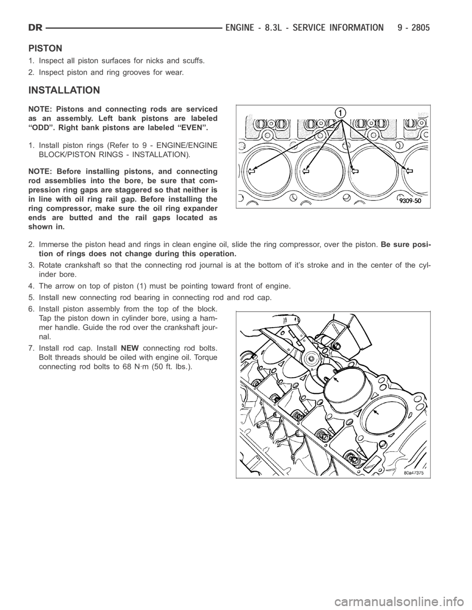
NOTE: Pistons and connecting rods are serviced
as an assembly. Left bank pistons are labeled
“ODD”. Right bank pistons are labeled “EVEN”.
1. Install piston rings (Refer to 9 - ENGINE/ENGINE
BLOCK/PISTON RINGS - INSTALLATION).
NOTE: Before installing pistons, and connecting
rod assemblies into the bore, be sure that com-
pression ring gaps are staggered so that neither is
in line with oil ring rail gap. Before installing the
ring compressor, make sure the oil ring expander
ends are butted and the rail gaps located as
shown in.
2. Immerse the piston head and rings in clean engine oil, slide the ring compressor, over the piston.Be sure posi-
tion of rings does not change during this operation.
3. Rotate crankshaft so that the connecting rod journal is at the bottom of it’s stroke and in the center of the cyl-
inder bore.
4. The arrow on top of piston (1) must be pointing toward front of engine.
5. Install new connecting rod bearing in connecting rod and rod cap.
6. Install piston assembly from the top of the block.
Tap the piston down in cylinder bore, using a ham-
mer handle. Guide the rod over the crankshaft jour-
nal.
7. Install rod cap. InstallNEWconnecting rod bolts.
Bolt threads should be oiled with engine oil. Torque
connecting rod bolts to 68 Nꞏm (50 ft. lbs.).
Page 2119 of 5267
BEARINGS-CONNECTING ROD
DESCRIPTION
The bearing caps are not interchangeable and should be paint marked or scribed at removal to insure correct
assembly.
The bearing shells must be installed so that the tangs are in the machined grooves in the rods and caps.
Limits of taper or out-of-round on any crankshaft journals should be held to 0.013 mm (0.0005 in.). Bearings are
available in 0.025 mm (0.001 in.), 0.051 mm (0.002 in.), 0.076 mm (0.003 in.), 0.254 mm (0.010 in.) and 0.305 mm
(0.012 in.) undersize.Install the bearings in pairs. Do not use a new bearing half with an old bearing half. Do
not file the rods or bearing caps.
STANDARD PROCEDURE
CONNECTING ROD BEARING - FITTING
Fit all rods on one bank until complete. Do not alternate from one bank to another, because when the rods are
assembled to pistons correctly, they are not interchangeable from one bank to another.
The bearing caps are not interchangeable and should be marked at removal toinsure correct assembly.
The bearing shells must be installed so that the tangs are in the machined grooves in the rods and caps.
Limits of taper or out-of-round on any crankshaft journals should be held to 0.013 mm (0.0005 in.). Bearings are
available in 0.025 mm (0.001 in.), 0.051 mm (0.002 in.), 0.076 mm (0.003 in.), 0.254 mm (0.010 in.) and 0.305 mm
(0.012 in.) undersize.Install the bearings in pairs. Do not use a new bearing half with an old bearing half. Do
not file the rods or bearing caps.
1. (Refer to 9 - ENGINE/ENGINE BLOCK/CONNECTING ROD BEARINGS - STANDARD PROCEDURE) - Mea-
suring Connecting Rod Bearing Clearance to determine bearing clearance.
2. Before installing the connecting rod cap bolts, the bolt threads shouldbe oiled with engine oil.
3. Install bolts finger tight, then alternately torque each bolt to assemble the cap properly.
4. Tighten the connecting rod bolts to 68 Nꞏm (50 ft. lbs.).
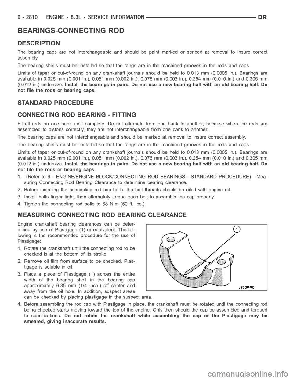
MEASURING CONNECTING ROD BEARING CLEARANCE
Engine crankshaft bearing clearances can be deter-
mined by use of Plastigage (1) or equivalent. The fol-
lowing is the recommended procedure for the use of
Plastigage:
1. Rotate the crankshaft until the connecting rod to be
checked is at the bottom of its stroke.
2. Remove oil film from surface to be checked. Plas-
tigage is soluble in oil.
3. Place a piece of Plastigage (1) across the entire
width of the bearing shell in the bearing cap
approximately 6.35 mm (1/4 inch.) off center and
away from the oil hole. In addition, suspect areas
can be checked by placing plastigage in the suspect area.
4. Before assembling the rod cap with Plastigage in place, the crankshaft must be rotated until the connecting rod
being checked starts moving toward the top of the engine. Only then should the cap be assembled and torqued
to specifications.Do not rotate the crankshaft while assembling the cap or the Plastigage maybe
smeared, giving inaccurate results.
Page 2123 of 5267
SEAL-CRANKSHAFT OIL- FRONT
REMOVAL
1. Disconnect the air inlet duct, IAT sensor, CCV hose
at the throttle body, and remove the air cleaner
housing cover.
2. Remove accessory drive belt (Refer to 7 - COOL-
ING/ACCESSORY DRIVE/DRIVE BELTS -
REMOVAL).
3. Remove crankshaft damper (Refer to 9 - ENGINE/
ENGINE BLOCK/CRANKSHAFT DAMPER -
REMOVAL).
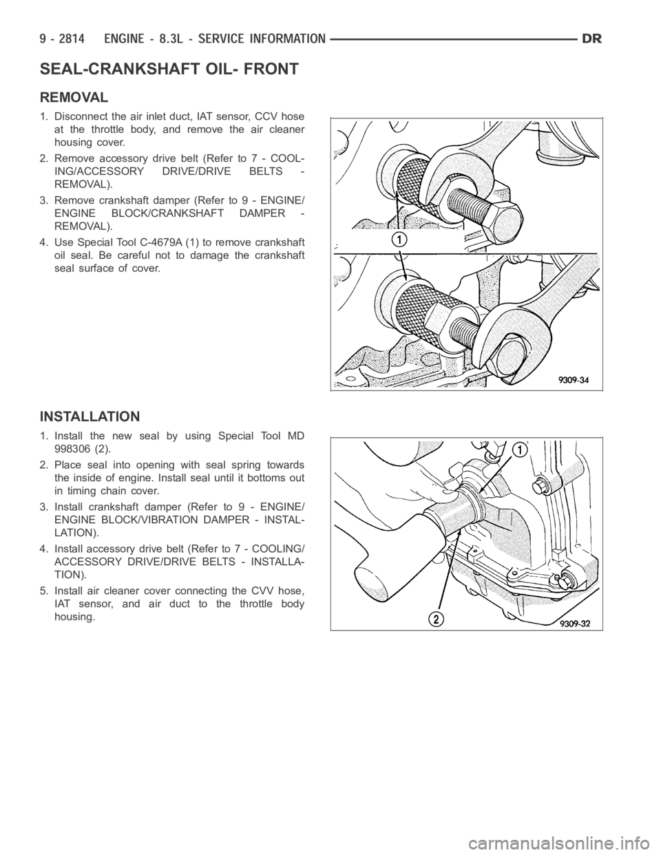
4. Use Special Tool C-4679A (1) to remove crankshaft
oil seal. Be careful not to damage the crankshaft
seal surface of cover.
INSTALLATION
1. Install the new seal by using Special Tool MD
998306 (2).
2. Place seal into opening with seal spring towards
the inside of engine. Install seal until it bottoms out
in timing chain cover.
3. Install crankshaft damper (Refer to 9 - ENGINE/
ENGINE BLOCK/VIBRATION DAMPER - INSTAL-
LATION).
4. Install accessory drive belt (Refer to 7 - COOLING/
ACCESSORY DRIVE/DRIVE BELTS - INSTALLA-
TION).
5. Install air cleaner cover connecting the CVV hose,
IAT sensor, and air duct to the throttle body
housing.