Page 4949 of 5267

When Monitored:
With the ignition on.
Set Condition:
If the Evaporator Temperature Sensor input is out of range toward the low voltage threshold, (A/D counts reach
low threshold of 3). This DTC has a maturing time of 5 seconds and a de-maturing time of 10 seconds. If the
DTC’s status changes from active to stored it will stay in memory for 100 ignition cycles.
Possible Causes
(C21) EVAPORATOR TEMPERATURE SENSOR SIGNAL CIRCUIT SHORTED TO GROUND
(C21) EVAPORATOR TEMPERATURE SENSOR SIGNAL CIRCUIT SHORTED TO (C121) SENSOR GROUND
CIRCUIT
EVAPORATOR TEMPERATURE SENSOR
A/C HEATER CONTROL
NOTE: This DTC must be active for the results of this test to be valid. Do not perform this test if this DTC
is stored. Refer to HVAC System Test for stored DTC test procedures.
Diagnostic Test
1.CHECK (C21) EVAPORATOR TEMPERATURE SENSOR SIGNAL CIRCUIT VOLTAGE WITH THE SENSOR
DISCONNECTED
Turn the ignition off.
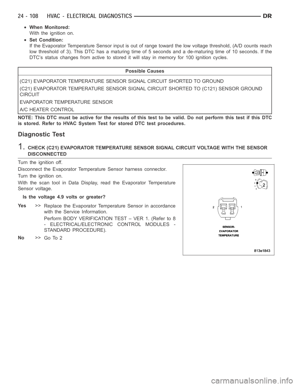
Disconnect the Evaporator Temperature Sensor harness connector.
Turn the ignition on.
With the scan tool in Data Display, read the Evaporator Temperature
Sensor voltage.
Is the voltage 4.9 volts or greater?
Ye s>>
Replace the Evaporator Temperature Sensor in accordance
with the Service Information.
Perform BODY VERIFICATION TEST – VER 1. (Refer to 8
- ELECTRICAL/ELECTRONIC CONTROL MODULES -
STANDARD PROCEDURE).
No>>
Go To 2
Page 4952 of 5267

When Monitored:
With the ignition on.
Set Condition:
If the Evaporator Temperature Sensor input is out of range toward the high voltage threshold, (A/D counts
reach high threshold of 253). This DTC has a maturing time of 5 seconds and a de-maturing time of 10 sec-
onds. If the DTC’s status changes from active to stored it will stay in memory for 100 ignition cycles.
Possible Causes
(C21) EVAPORATOR TEMPERATURE SENSOR SIGNAL CIRCUIT SHORTED TO VOLTAGE
(C21) EVAPORATOR TEMPERATURE SENSOR SIGNAL CIRCUIT OPEN
(C121) SENSOR GROUND CIRCUIT OPEN
EVAPORATOR TEMPERATURE SENSOR
A/C HEATER CONTROL
NOTE: This DTC must be active for the results of this test to be valid. Do not perform this test if this DTC
is stored. Refer to HVAC System Test for stored DTC test procedures.
Diagnostic Test
1.CHECK (C21) EVAPORATOR TEMPERATURE SENSOR SIGNAL CIRCUIT FOR A SHORT TO VOLTA G E
Turn the ignition off.
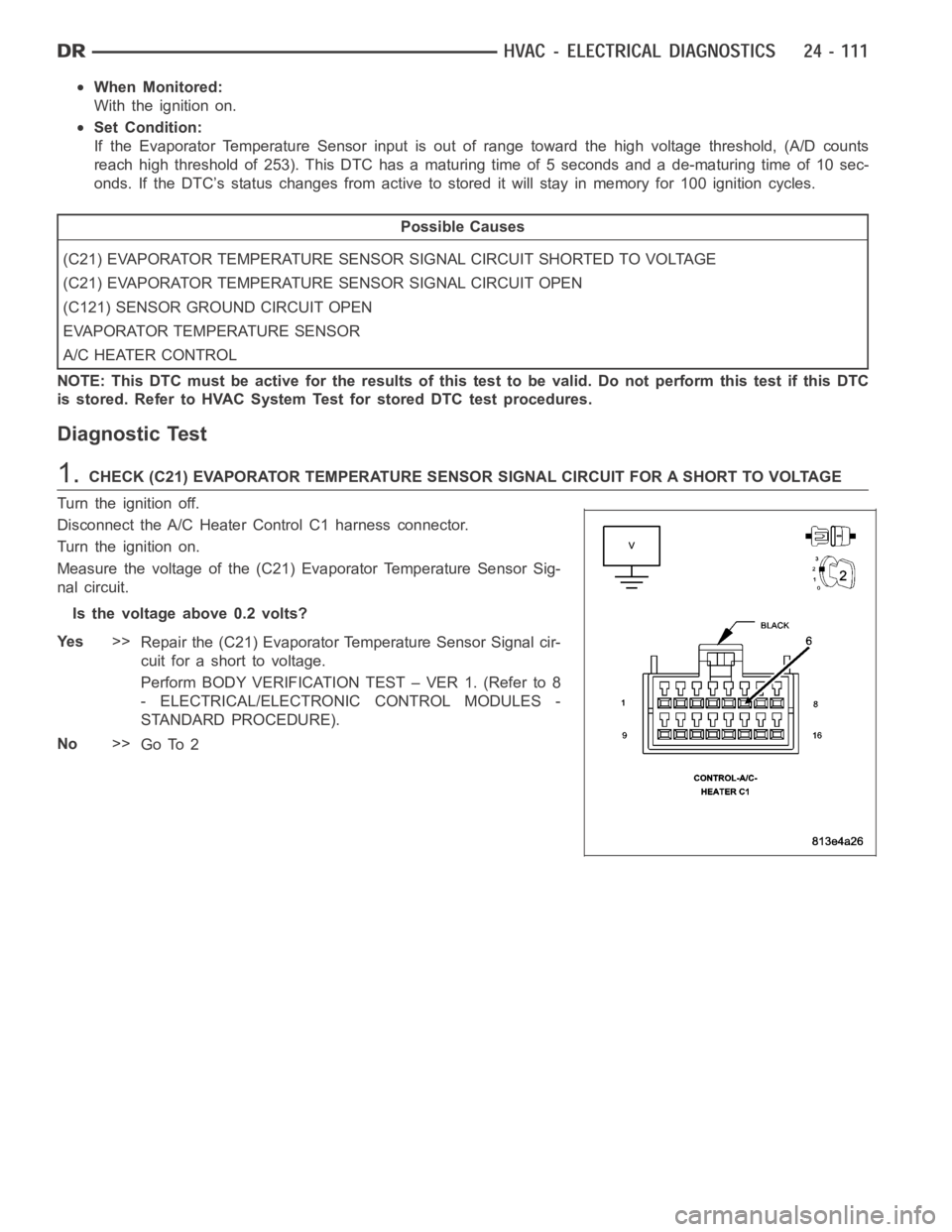
Disconnect the A/C Heater Control C1 harness connector.
Turn the ignition on.
Measure the voltage of the (C21) Evaporator Temperature Sensor Sig-
nal circuit.
Is the voltage above 0.2 volts?
Ye s>>
Repair the (C21) Evaporator Temperature Sensor Signal cir-
cuit for a short to voltage.
Perform BODY VERIFICATION TEST – VER 1. (Refer to 8
- ELECTRICAL/ELECTRONIC CONTROL MODULES -
STANDARD PROCEDURE).
No>>
Go To 2
Page 5224 of 5267

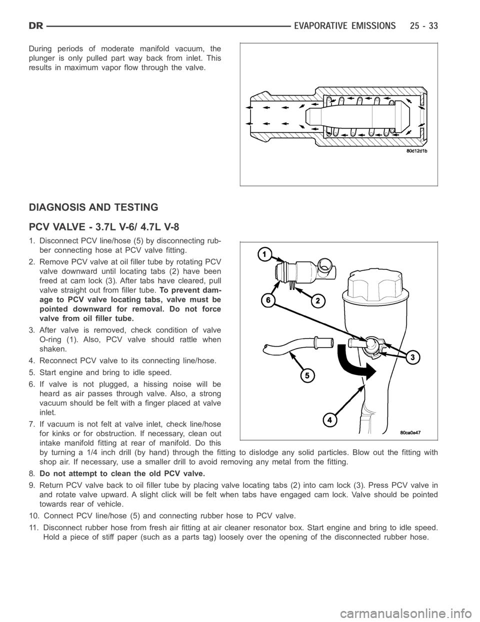
During periods of moderate manifold vacuum, the
plunger is only pulled part way back from inlet. This
results in maximum vapor flow through the valve.
DIAGNOSIS AND TESTING
PCVVALVE-3.7LV-6/4.7LV-8
1. Disconnect PCV line/hose (5) by disconnecting rub-
ber connecting hose at PCV valve fitting.
2. Remove PCV valve at oil filler tube by rotating PCV
valve downward until locating tabs (2) have been
freed at cam lock (3). After tabs have cleared, pull
valve straight out from filler tube.To prevent dam-
age to PCV valve locating tabs, valve must be
pointed downward for removal. Do not force
valve from oil filler tube.
3. After valve is removed, check condition of valve
O-ring (1). Also, PCV valve should rattle when
shaken.
4. Reconnect PCV valve to its connecting line/hose.
5. Start engine and bring to idle speed.
6. If valve is not plugged, a hissing noise will be
heard as air passes through valve. Also, a strong
vacuum should be felt with a finger placed at valve
inlet.
7. If vacuum is not felt at valve inlet, check line/hose
for kinks or for obstruction. If necessary, clean out
intake manifold fitting at rear of manifold. Do this
byturninga1/4inchdrill(byhand)throughthefittingtodislodgeanysolid particles. Blow out the fitting with
shop air. If necessary, use a smaller drill to avoid removing any metal fromthe fitting.
8.Do not attempt to clean the old PCV valve.
9. Return PCV valve back to oil filler tube by placing valve locating tabs (2) into cam lock (3). Press PCV valve in
and rotate valve upward. A slight click will be felt when tabs have engaged cam lock. Valve should be pointed
towards rear of vehicle.
10. Connect PCV line/hose (5) and connecting rubber hose to PCV valve.
11. Disconnect rubber hose from fresh air fitting at air cleaner resonatorbox. Start engine and bring to idle speed.
Hold a piece of stiff paper (such as a parts tag) loosely over the opening of the disconnected rubber hose.
Page 5227 of 5267

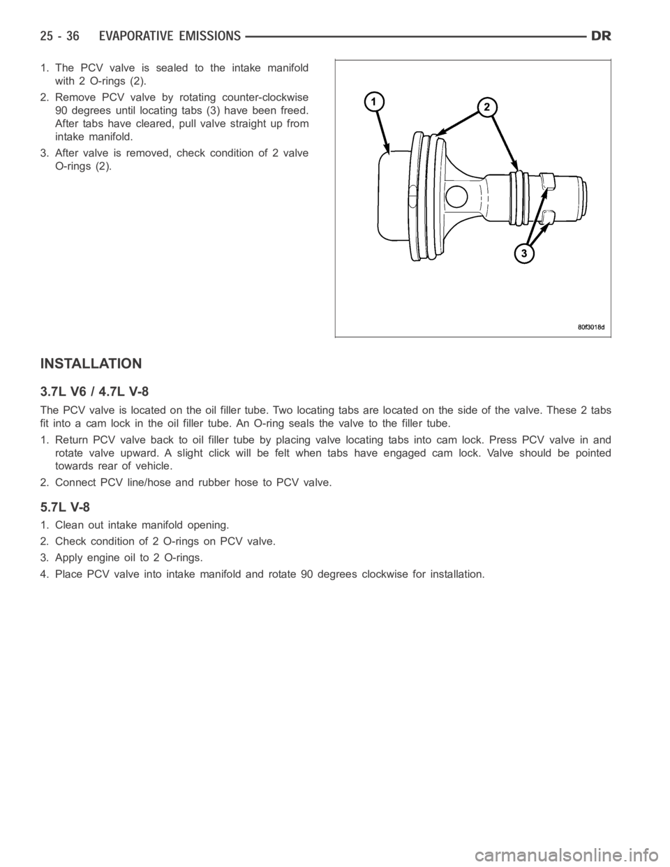
1. The PCV valve is sealed to the intake manifold
with 2 O-rings (2).
2. Remove PCV valve by rotating counter-clockwise
90 degrees until locating tabs (3) have been freed.
After tabs have cleared, pull valve straight up from
intake manifold.
3. After valve is removed, check condition of 2 valve
O-rings (2).
INSTALLATION
3.7L V6 / 4.7L V-8
The PCV valve is located on the oil filler tube. Two locating tabs are locatedonthesideofthevalve.These2tabs
fit into a cam lock in the oil filler tube.An O-ring seals the valve to the filler tube.
1. Return PCV valve back to oil filler tube by placing valve locating tabs into cam lock. Press PCV valve in and
rotate valve upward. A slight click will be felt when tabs have engaged cam lock. Valve should be pointed
towards rear of vehicle.
2. Connect PCV line/hose and rubber hose to PCV valve.
5.7L V-8
1. Clean out intake manifold opening.
2. Check condition of 2 O-rings on PCV valve.
3. Apply engine oil to 2 O-rings.
4. Place PCV valve into intake manifold and rotate 90 degrees clockwise forinstallation.