2006 DODGE RAM SRT-10 tow
[x] Cancel search: towPage 3585 of 5267
3.CHECK IF THE DTC IS CURRENT
With the scan tool, read Engine DTCs.
Record the Freeze Frame data for the reported DTC.
With the scan tool, erase DTCs.
Turn the ignition off to the lock position.
Using the Freeze Frame data recorded earlier, try to duplicate the conditions in which the DTC originally set.
NOTE: It may be necessary to road test the vehicle to duplicate the originalset conditions.
With the scan tool, read Engine DTCs.
Did the DTC reset?
Ye s>>
Go To 4
No>>
Go To 14
4.VERIFY THE TOW/ HAUL OVERDRIVE FEATURE
NOTE: The transmission fluid temperature must be above 0.0° C (32° F) before proceeding.
With the scan tool, build a custom display using: Engine RPM, Output Shaft Speed, TCC Solenoid, O/D Solenoid
and TPS.
NOTE: This display will monitor the operation of the components.
Start the engine, turn off Overdrive or Tow Haul and test drive the vehicle.
Attain a steady speed of 88.5 Km/h or 55 MPH with a minimum of 1.15 volts throttle opening for 20 seconds.
NOTE: Check the Shift pattern as the vehicle upshifts to speeds of 88.5 Km/hor 55 MPH.
Is the Engine RPM within 60 RPM of the Output Shaft Speed RPM?
Ye s>>
Go To 10
No>>
Go To 5
5.CHECK IF THE OUTPUT SPEED IS GREATER THAN ENGINE RPM
In the previous test, is the Output Shaft Speed greater than Engine RPM?
Ye s>>
Go To 6
No>>
Go To 10
6.CALCULATE EXPECTED ENGINE RPM
With the scan tool, build a custom display using: Engine RPM, Output Shaft Speed, TCC Solenoid, O/D Solenoid
and TPS.
NOTE: This display will monitor the operation of the components.
Start the engine, turn off Overdrive or Tow Haul and test drive the vehicle.
Attain a steady speed of 88.5 Km/h or 55 MPH with a minimum of 1.15 volts throttle opening for 20 seconds.
With the scan tool, verify the 3-4 Solenoid (O/D) Solenoid is on and the TCC solenoid is locked
NOTE: Use this formula, Output Shaft Speed x 0.69 = expected Engine RPM.
Did the Engine RPM drop to 0.69 of the Output Shaft Speed RPM?
Ye s>>
Go To 10
No>>
Go To 7
Page 3626 of 5267
page page
AUTOMATIC TRANSMISSION - 48RE - DIESEL -
ELECTRICAL DIAGNOSTICS
DIAGNOSIS AND TESTING
P0711-TRANS TEMP SENSOR, NO TEMP
RISE AFTER START (DIESEL).............. 1107
P0712-TRANS TEMP SENSOR VOLTAGE
TOO LOW (DIESEL).......................1111
P0713-TRANS TEMP SENSOR VOLTAGE
TOO HIGH................................ 1117
P0720-LOW OUTPUT SPEED SENSOR -
RPM ABOVE 15 MPH (DIESEL)............ 1125
P0748-PRESSURE SOL CONTROL/TRANS
RELAY CIRCUITS (DIESEL)................ 1131
P0850-P/N SWITCH PERFORMANCE
(DIESEL)................................. 1138
P0868-GOVERNOR PRESSURE SENSOR
VOLTS TOO HI (DIESEL).................. 1143
P0869-GOVERNOR PRESSURE SENSOR
VOLTS TOO LOW (DIESEL)................ 1150
P0882-TRANS 12 VOLT SUPPLY RELAY
CONTROL CIRCUIT LOW (DIESEL)......... 1155
P0883-TRANS 12 VOLT SUPPLY RELAY
CONTROL CIRCUIT HIGH (DIESEL)........ 1159
P0973-TRANSMISSION OVERDRIVE
CIRCUIT VOLTAGE TOO LOW (DIESEL).... 1163
P0974-TRANSMISSION OVERDRIVE
CIRCUIT VOLTAGE TOO HIGH (DIESEL).... 1171
P128B-TCM POWER CONTROL CIRCUIT 2
LOW - TIPM.............................. 1176
P128C-TCM POWER CONTROL CIRCUIT 2
HIGH - TIPM.............................. 1179
P128D-TCM POWER CONTROL CIRCUIT 2
OPEN - TIPM............................. 1182
P128E-TCM POWER CONTROL CIRCUIT 2
OVERCURRENT - TIPM................... 1185P1740-TCC O/D SOL PERFORMANCE
(DIESEL)................................. 1189
P1749-TRANSMISSION THROTTLE VALVE
POSITION SENSOR CIRCUIT LOW......... 1194
P1750-TRANSMISSION THROTTLE VALVE
POSITION SENSOR CIRCUIT HIGH........ 1200
P1751-TRANSMISSION THROTTLE VALVE
POSITION MINIMUM RANGE
PERFORMANCE.......................... 1205
P1752-TRANSMISSION THROTTLE VALVE
SPAN PERFORMANCE.................... 1208
P1753-TRANSMISSION THROTTLE VALVE
MECHANICAL PERFORMANCE............ 1211
P1754-TRANSMISSION THROTTLE VALVE
ACTUATOR STUCK....................... 1214
P1755-TRANSMISSION THROTTLE VALVE
CONTROL CIRCUIT....................... 1223
P1756-GOV PRESS NOT EQUAL TO
TARGET @ 35 - 40 PSI (DIESEL)........... 1231
P1757-GOV PRESS ABOVE 3 PSI IN GEAR
WITH 0 MPH (DIESEL).................... 1238
P1762-GOV PRESS SENSOR OFFSET
VOLTS TOO LOW OR HIGH (DIESEL)...... 1244
P2769-TRANSMISSION TCC CONTROL
CIRCUIT LOW............................ 1249
P2770-TRANSMISSION TCC CONTROL
CIRCUIT HIGH (DIESEL).................. 1256
*TOW /HAUL OVERDRIVE OFF SWITCH
(DIESEL)................................. 1261
STANDARD PROCEDURE
TRANSMISSION VERIFICATION TEST VER -
1 (DIESEL)............................... 1264
PRE-DIAGNOSTIC CHECKOUT (DIESEL) . . . 1265
Page 3711 of 5267
3.CHECK IF THE DTC IS CURRENT
With the scan tool, read Engine DTCs.
Record the Freeze Frame data for the reported DTC.
With the scan tool, erase DTCs.
Turn the ignition off to the lock position.
Using the Freeze Frame data recorded earlier, try to duplicate the conditions in which the DTC originally set.
NOTE: It may be necessary to road test the vehicle to duplicate the originalset conditions.
With the scan tool, read Engine DTCs.
Did the DTC reset?
Ye s>>
Go To 4
No>>
Go To 14
4.VERIFY THE TOW/ HAUL OVERDRIVE FEATURE
NOTE: The transmission fluid temperature must be above 0.0° C (32° F) before proceeding.
With the scan tool, build a custom display using: Engine RPM, Output Shaft Speed, TCC Solenoid, O/D Solenoid
and TPS.
NOTE: This display will monitor the operation of the components.
Start the engine, turn off Overdrive or Tow Haul and test drive the vehicle.
Attain a steady speed of 88.5 Kmh or 55 mph with a minimum of 1.15 volts throttle opening for 20 seconds.
NOTE: Check the Shift pattern as the vehicle upshifts to speeds of 88.5 Kmh or55mph.
Is the Engine RPM within 60 RPM of the Output Shaft Speed RPM?
Ye s>>
Go To 10
No>>
Go To 5
5.CHECK IF THE OUTPUT SPEED IS GREATER THAN ENGINE RPM
In the previous test, is the Output Shaft Speed greater than Engine RPM?
Ye s>>
Go To 6
No>>
Go To 10
6.CALCULATE EXPECTED ENGINE RPM
With the scan tool, build a custom display using: Engine RPM, Output Shaft Speed, TCC Solenoid, O/D Solenoid
and TPS.
NOTE: This display will monitor the operation of the components.
Start the engine, turn off Overdrive or Tow Haul and test drive the vehicle.
Attain a steady speed of 88.5 Kmh or 55 mph with a minimum of 1.15 volts throttle opening for 20 seconds.
With the scan tool, verify the 3-4 Solenoid (O/D) Solenoid is on and the TCC solenoid is locked
NOTE: Use this formula, Output Shaft Speed x 0.69 = expected Engine RPM.
Did the Engine RPM drop to 0.69 of the Output Shaft Speed RPM?
Ye s>>
Go To 10
No>>
Go To 7
Page 3782 of 5267
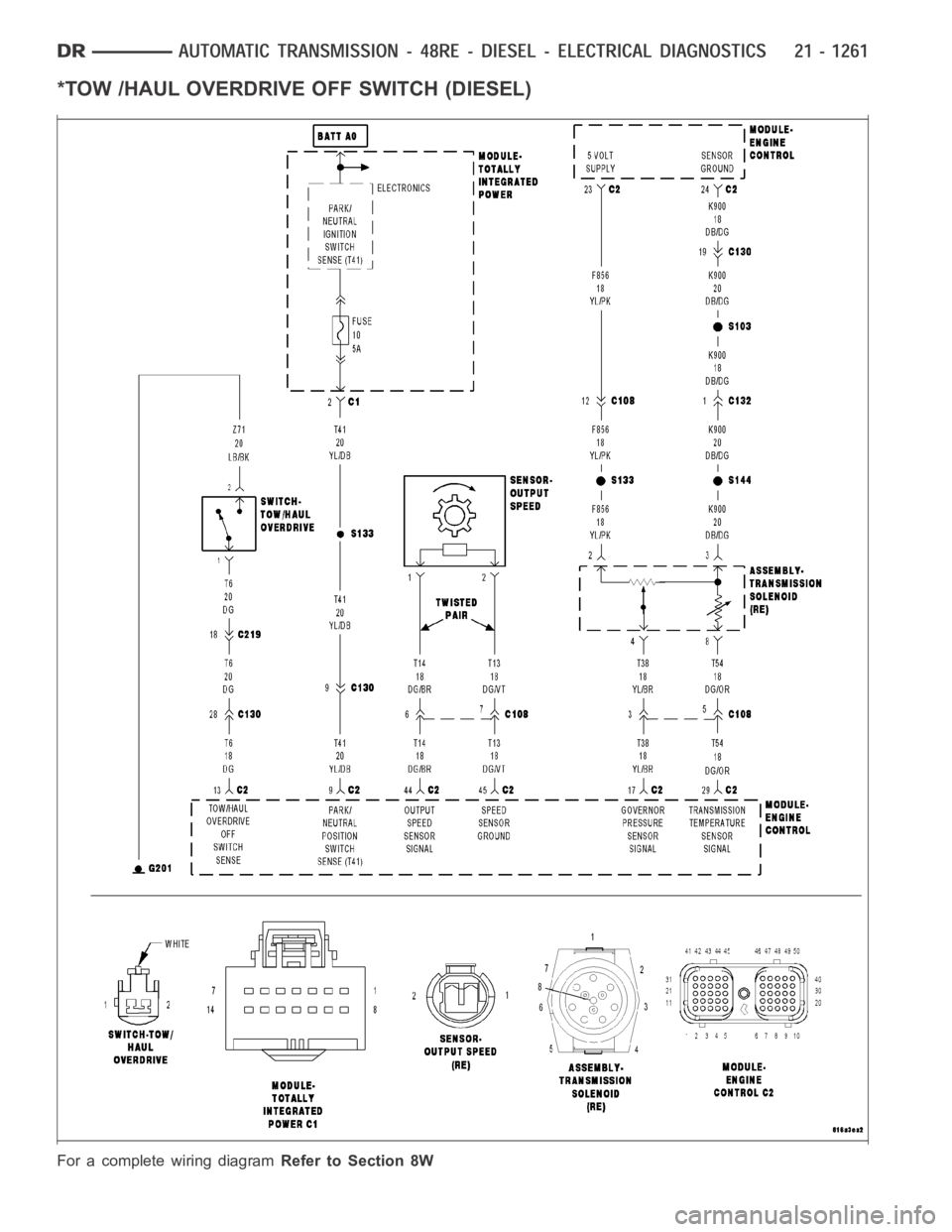
*TOW /HAUL OVERDRIVE OFF SWITCH (DIESEL)
For a complete wiring diagramRefer to Section 8W
Page 3783 of 5267
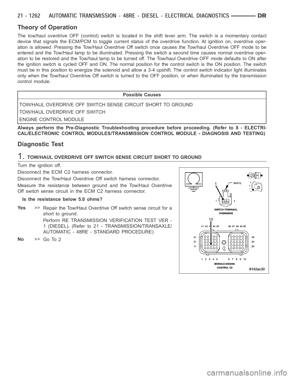
Theory of Operation
The tow/haul overdrive OFF (control) switch is located in the shift lever arm. The switch is a momentary contact
device that signals the ECM/PCM to toggle current status of the overdrive function. At ignition on, overdrive oper-
ation is allowed. Pressing the Tow/Haul Overdrive Off switch once causes the Tow/haul Overdrive OFF mode to be
entered and the Tow/Haul lamp to be illuminated. Pressing the switch a second time causes normal overdrive oper-
ationtoberestoredandtheTow/haullamptobeturnedoff.TheTow/haulOverdrive OFF mode defaults to ON after
the ignition switch is cycled OFF and ON. The normal position for the control switch is the ON position. The switch
must be in this position to energize the solenoid and allow a 3-4 upshift. The control switch indicator light illuminates
only when the Tow/haul Overdrive Off switch is turned to the OFF position, or when illuminated by the transmission
control module.
Possible Causes
TOW/HAUL OVERDRIVE OFF SWITCH SENSE CIRCUIT SHORT TO GROUND
TOW/HAUL OVERDRIVE OFF SWITCH
ENGINE CONTROL MODULE
Always perform the Pre-Diagnostic Troubleshooting procedure before proceeding. (Refer to 8 - ELECTRI-
CAL/ELECTRONIC CONTROL MODULES/TRANSMISSION CONTROL MODULE - DIAGNOSIS AND TESTING)
Diagnostic Test
1.TOW/HAUL OVERDRIVE OFF SWITCH SENSE CIRCUIT SHORT TO GROUND
Turn the ignition off.
Disconnect the ECM C2 harness connector.
Disconnect the Tow/Haul OverdriveOff switch harness connector.
Measure the resistance between ground and the Tow/Haul Overdrive
Off switch sense circuit in the ECM C2 harness connector.
Is the resistance below 5.0 ohms?
Ye s>>
Repair the Tow/Haul Overdrive Off switch sense circuit for a
short to ground.
Perform RE TRANSMISSION VERIFICATION TEST VER -
1 (DIESEL). (Refer to 21 - TRANSMISSION/TRANSAXLE/
AUTOMATIC - 48RE - STANDARD PROCEDURE)
No>>
Go To 2
Page 3784 of 5267
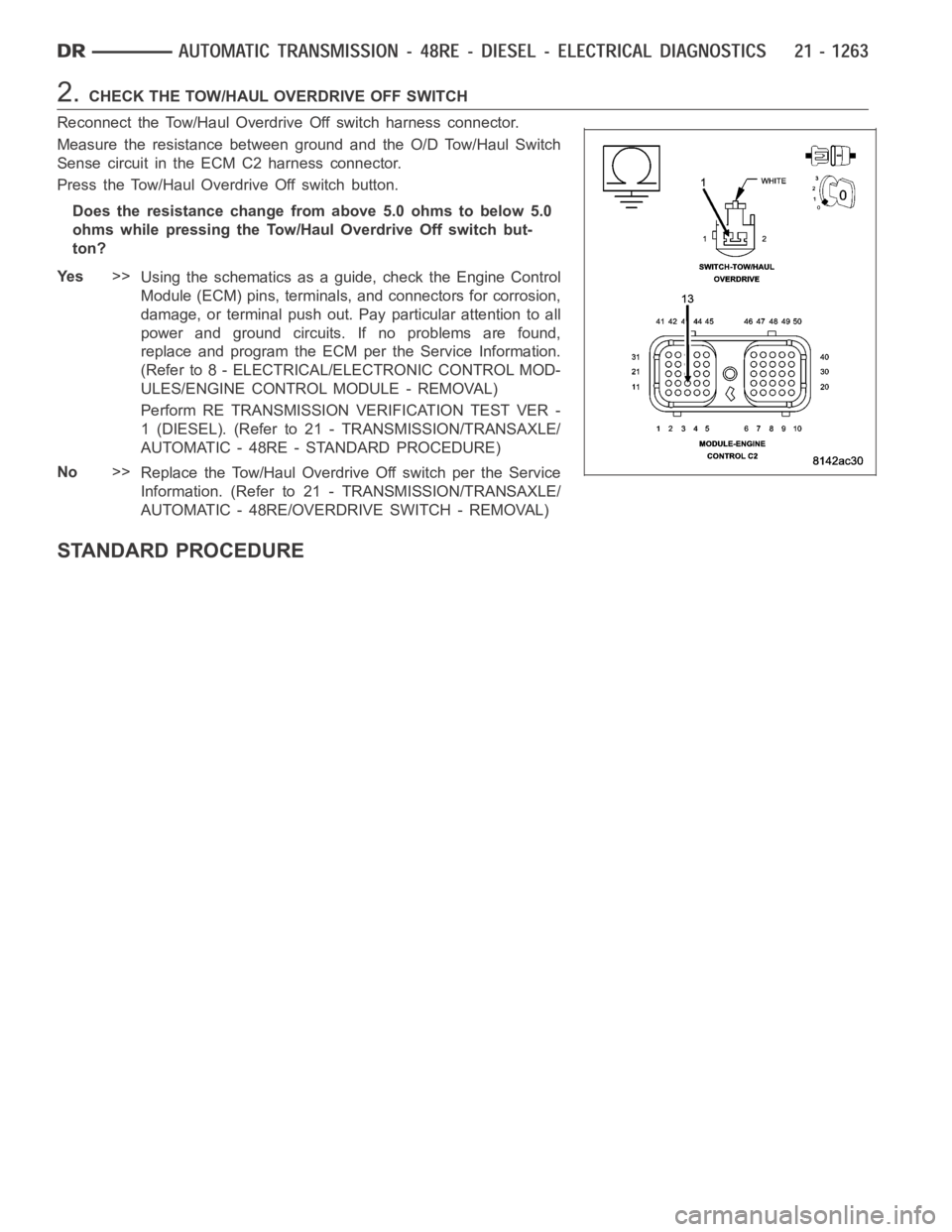
2.CHECK THE TOW/HAUL OVERDRIVE OFF SWITCH
Reconnect the Tow/Haul Overdrive Off switch harness connector.
Measure the resistance between ground and the O/D Tow/Haul Switch
Sense circuit in the ECM C2 harness connector.
Press the Tow/Haul Overdrive Off switch button.
Does the resistance change from above 5.0 ohms to below 5.0
ohms while pressing the Tow/Haul Overdrive Off switch but-
ton?
Ye s>>
Using the schematics as a guide, check the Engine Control
Module (ECM) pins, terminals, and connectors for corrosion,
damage, or terminal push out. Pay particular attention to all
power and ground circuits. If no problems are found,
replace and program the ECM per the Service Information.
(Refer to 8 - ELECTRICAL/ELECTRONIC CONTROL MOD-
ULES/ENGINE CONTROL MODULE - REMOVAL)
Perform RE TRANSMISSION VERIFICATION TEST VER -
1 (DIESEL). (Refer to 21 - TRANSMISSION/TRANSAXLE/
AUTOMATIC - 48RE - STANDARD PROCEDURE)
No>>
Replace the Tow/Haul Overdrive Off switch per the Service
Information. (Refer to 21 - TRANSMISSION/TRANSAXLE/
AUTOMATIC - 48RE/OVERDRIVE SWITCH - REMOVAL)
STANDARD PROCEDURE
Page 3788 of 5267
CLEANING ................................. 1389
INSPECTION ............................... 1389
ASSEMBLY . ............................... 1390
INSTALLATION ............................. 1400
RETAINER-OVERRUNNING CLUTCH CAM/
OVERDRIVE PISTON
DESCRIPTION ............................. 1402
OPERATION ............................... 1402
DISASSEMBLY ............................. 1402
CLEANING ................................. 1403
INSPECTION ............................... 1403
ASSEMBLY . ............................... 1403
SHAFT-PLANETARY GEARTRAIN/OUTPUT
DESCRIPTION ............................. 1407
OPERATION ............................... 1407
DISASSEMBLY ............................. 1407
INSPECTION ............................... 1410
ASSEMBLY ................................ 1410
CLUTCH-REAR
DESCRIPTION ............................. 1416
OPERATION ............................... 1416
DISASSEMBLY ............................. 1417
CLEANING ................................. 1417
INSPECTION ............................... 1418
ASSEMBLY ................................ 1418
SERVO-REAR
DESCRIPTION ............................. 1421
OPERATION ............................... 1421
DISASSEMBLY ............................. 1421
CLEANING ................................. 1421
ASSEMBLY ................................ 1421
MECHANISM-SHIFT
DESCRIPTION ............................. 1422
OPERATION ............................... 1422
SENSOR-SPEED
DESCRIPTION ............................. 1423
OPERATION ............................... 1423
ACTUATOR-THROTTLE VALVE
DESCRIPTION ............................. 1424
REMOVAL ................................. 1424
INSTALLATION ............................. 1425
ADJUSTMENTS
ADJUSTMENT ............................ 1426
CABLE-THROTTLE VALVE
DESCRIPTION ............................. 1427ADJUSTMENTS - THROTTLE VALVE CABLE . . 1428
CONVERTER-TORQUE
DESCRIPTION ............................. 1431
OPERATION ............................... 1435
REMOVAL ................................. 1436
INSTALLATION ............................. 1437
VALVE-TORQUE CONVERTER DRAINBACK
DESCRIPTION
GAS ENGINES ........................... 1438
DIESEL ENGINE .......................... 1438
OPERATION
GAS ENGINES ........................... 1438
DIESEL ENGINE .......................... 1438
STANDARD PROCEDURE
GAS ENGINES ........................... 1438
DIESEL ENGINE .......................... 1438
SWITCH-TOW/HAUL OVERDRIVE
DESCRIPTION ............................. 1440
OPERATION ............................... 1440
DIAGNOSIS AND TESTING - OVERDRIVE
ELECTRICAL CONTROLS ................. 1440
REMOVAL ................................. 1440
INSTALLATION ............................. 1441
SENSOR-TRANSMISSION RANGE
DESCRIPTION ............................. 1442
OPERATION ............................... 1442
DIAGNOSIS AND TESTING - TRANSMISSION
RANGE SENSOR (TRS) ................... 1443
REMOVAL ................................. 1444
INSTALLATION ............................. 1445
SENSOR-TRANSMISSION TEMPERATURE
DESCRIPTION ............................. 1447
OPERATION ............................... 1447
BODY-VALVE
DESCRIPTION ............................. 1448
OPERATION ............................... 1451
REMOVAL ................................. 1471
DISASSEMBLY ............................. 1472
CLEANING ................................. 1485
INSPECTION ............................... 1485
ASSEMBLY................................ 1486
INSTALLATION ............................. 1497
ADJUSTMENTS - VALVE BODY .............. 1498
Page 3797 of 5267
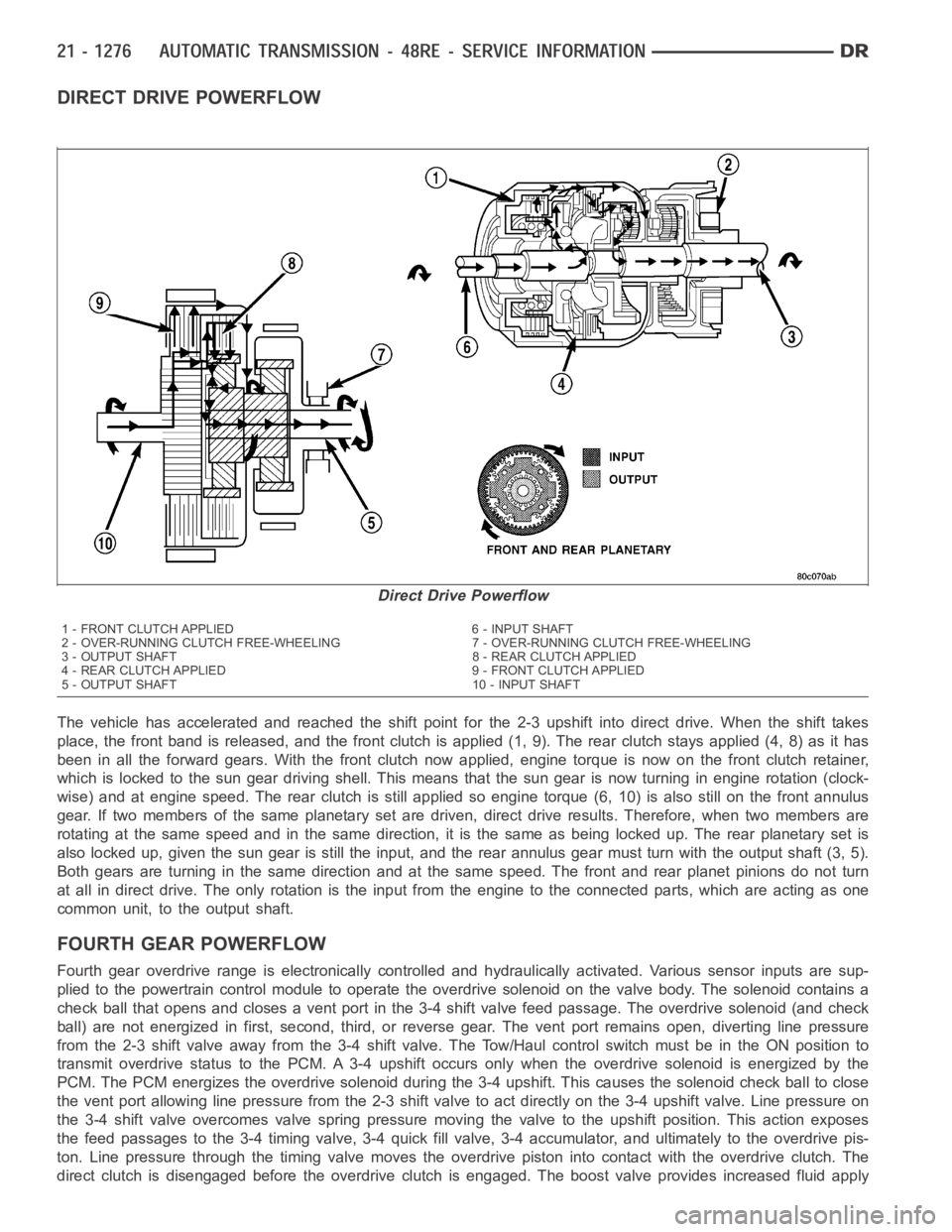
DIRECT DRIVE POWERFLOW
The vehicle has accelerated and reached the shift point for the 2-3 upshiftinto direct drive. When the shift takes
place, the front band is released, and the front clutch is applied (1, 9). The rear clutch stays applied (4, 8) as it has
been in all the forward gears. With the front clutch now applied, engine torque is now on the front clutch retainer,
which is locked to the sun gear drivingshell. This means that the sun gear isnow turning in engine rotation (clock-
wise) and at engine speed. The rear clutch is still applied so engine torque(6, 10) is also still on the front annulus
gear. If two members of the same planetary set are driven, direct drive results. Therefore, when two members are
rotating at the same speed and in the same direction, it is the same as being locked up. The rear planetary set is
also locked up, given the sun gear is still the input, and the rear annulus gear must turn with the output shaft (3, 5).
Both gears are turning in the same direction and at the same speed. The frontand rear planet pinions do not turn
at all in direct drive. The only rotation is the input from the engine to the connected parts, which are acting as one
common unit, to the output shaft.
FOURTHGEARPOWERFLOW
Fourth gear overdrive range is electronically controlled and hydraulically activated. Various sensor inputs are sup-
plied to the powertrain control module to operate the overdrive solenoid on the valve body. The solenoid contains a
check ball that opens and closes a vent port in the 3-4 shift valve feed passage. The overdrive solenoid (and check
ball) are not energized in first, second, third, or reverse gear. The vent port remains open, diverting line pressure
from the 2-3 shift valve away from the 3-4 shift valve. The Tow/Haul controlswitch must be in the ON position to
transmit overdrive status to the PCM. A 3-4 upshift occurs only when the overdrive solenoid is energized by the
PCM. The PCM energizes the overdrive solenoid during the 3-4 upshift. Thiscauses the solenoid check ball to close
the vent port allowing line pressure from the 2-3 shift valve to act directly on the 3-4 upshift valve. Line pressure on
the 3-4 shift valve overcomes valve spring pressure moving the valve to theupshift position. This action exposes
the feed passages to the 3-4 timing valve, 3-4 quick fill valve, 3-4 accumulator, and ultimately to the overdrive pis-
ton. Line pressure through the timing valve moves the overdrive piston into contact with the overdrive clutch. The
direct clutch is disengaged before the overdrive clutch is engaged. The boost valve provides increased fluid apply
Direct Drive Powerflow
1 - FRONT CLUTCH APPLIED 6 - INPUT SHAFT
2 - OVER-RUNNING CLUTCH FREE-WHEELING 7 - OVER-RUNNING CLUTCH FREE-WHEELING
3 - OUTPUT SHAFT 8 - REAR CLUTCH APPLIED
4 - REAR CLUTCH APPLIED 9 - FRONT CLUTCH APPLIED
5 - OUTPUT SHAFT 10 - INPUT SHAFT