2006 DODGE RAM SRT-10 tow
[x] Cancel search: towPage 3304 of 5267
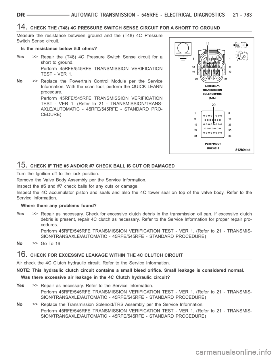
14.CHECK THE (T48) 4C PRESSURE SWITCH SENSE CIRCUIT FOR A SHORT TO GROUND
Measure the resistance between ground and the (T48) 4C Pressure
Switch Sense circuit.
Is the resistance below 5.0 ohms?
Ye s>>
Repair the (T48) 4C Pressure Switch Sense circuit for a
short to ground.
Perform 45RFE/545RFE TRANSMISSION VERIFICATION
TEST - VER 1.
No>>
Replace the Powertrain Control Module per the Service
Information. With the scan tool, perform the QUICK LEARN
procedure.
Perform 45RFE/545RFE TRANSMISSION VERIFICATION
TEST - VER 1. (Refer to 21 - TRANSMISSION/TRANS-
AXLE/AUTOMATIC - 45RFE/545RFE - STANDARD PRO-
CEDURE)
15.CHECK IF THE #5 AND/OR #7 CHECK BALL IS CUT OR DAMAGED
Turn the Ignition off to the lock position.
Remove the Valve Body Assembly per the Service Information.
Inspect the #5 and #7 check balls for any cuts or damage.
Inspect the 4C accumulator piston and seals and also the 4C tower seal on topof the valve body. Refer to the
Service Information.
Where there any problems found?
Ye s>>
Repair as necessary. Check for excessive clutch debris in the transmission oil pan. If excessive clutch
debris is present, repair 4C clutch as necessary. Refer to the Service Information for proper repair pro-
cedures.
Perform 45RFE/545RFE TRANSMISSION VERIFICATION TEST - VER 1. (Refer to 21- TRANSMIS-
SION/TRANSAXLE/AUTOMATIC - 45RFE/545RFE - STANDARD PROCEDURE)
No>>
Go To 16
16.CHECK FOR EXCESSIVE LEAKAGE WITHIN THE 4C CLUTCH CIRCUIT
Air check the 4C Clutch hydraulic circuit. Refer to the Service Information.
NOTE: This hydraulic clutch circuit contains a small bleed orifice. Smallleakage is considered normal.
Was there excessive air leakage in the 4C Clutch hydraulic circuit?
Ye s>>
Repair as necessary. Refer to the Service Information.
Perform 45RFE/545RFE TRANSMISSION VERIFICATION TEST - VER 1. (Refer to 21- TRANSMIS-
SION/TRANSAXLE/AUTOMATIC - 45RFE/545RFE - STANDARD PROCEDURE)
No>>
Replace the Transmission Solenoid/TRS Assembly per the Service Information.
Perform 45RFE/545RFE TRANSMISSION VERIFICATION TEST - VER 1. (Refer to 21- TRANSMIS-
SION/TRANSAXLE/AUTOMATIC - 45RFE/545RFE - STANDARD PROCEDURE)
Page 3320 of 5267
P1715-RESTRICTED MANUAL VALVE IN T3 RANGE
For a complete wiring diagramRefer to Section 8W
When Monitored:
Whenever the PRNDL code indicates Temp 3.
Set Condition:
This DTC sets when conditions for the DTC P1776 are satisfied or 3 unsuccessful attempts to engage 1st gear
while the shifter is in the temp 3 zone. This indicates a restricted port at the manual valve because the shifter
is not fully engaged in the drive position.
Possible Causes
RELATED TRANSMISSION DTC’S PRESENT
CUSTOMER DRIVING HABITS
MISADJUSTED SHIFTER
Always perform the 45RFE/545RFE Pre-Diagnostic Troubleshooting Procedure before proceeding. (Refer to
21 - TRANSMISSION/TRANSAXLE/AUTOMATIC - 45RFE/545RFE - STANDARD PROCEDURE)
Diagnostic Test
1.DETERMINING IF RELATED DTC’S ARE PRESENT
With the scan tool, check for other transmission DTC’s
Are any of the following DTC’s P0731, P0732, P0733, P0734, P1736 or P0715 present?
Ye s>>
Refer to the Transmission category and perform the appropriate symptom.
No>>
Go To 2
2.CHECK SHIFTER ADJUSTMENT
Check Shifter adjustment per the Service Information.
Is the shifter properly adjusted?
Ye s>>
Go To 3
No>>
Adjust the Shifter Assembly per the Service Information.
Perform 45RFE/545RFE TRANSMISSION VERIFICATION TEST - VER 1. (Refer to 21- TRANSMIS-
SION/TRANSAXLE/AUTOMATIC - 45RFE/545RFE - STANDARD PROCEDURE)
3.CHECK CUSTOMER DRIVING HABIT
This DTC can be set if the customer rests their hand on the shift lever while they are driving. The transmission can
be put in the T3 position if just enough forward pressure is exerted on the shift lever.
When this occurs, the feed port to the clutch is restricted, the transmission will declare neutral, and this DTC will be
set. The customer should be informed not to rest their hand on the shifter while driving.
This DTC can also be set by simply bumping the shift lever toward neutral while accelerating.
With the scan tool, check the DTC EVENT DATA to help identify the conditionsin which the DTC was set.
If there are no possible causes remaining, view repair.
Repair
This DTC can be set by putting too much forward pressure on the shift lever while it is in the OD posi-
tion. Make sure the customer is informed.
Perform 45RFE/545RFE TRANSMISSION VERIFICATION TEST - VER 1. (Refer to 21- TRANSMIS-
SION/TRANSAXLE/AUTOMATIC - 45RFE/545RFE - STANDARD PROCEDURE)
Page 3363 of 5267
page page
AUTOMATIC TRANSMISSION - 45RFE/545RFE -
SERVICE INFORMATION
DESCRIPTION ............................... 844
OPERATION ................................. 845
DIAGNOSIS AND TESTING
AUTOMATIC TRANSMISSION ............... 845
PRELIMINARY ............................. 846
ROAD TESTING ........................... 846
HYDRAULIC PRESSURE TEST............. 847
AIR CHECKING TRANSMISSION CLUTCH
OPERATION............................... 850
CONVERTER HOUSING FLUID LEAK ....... 850
STANDARD PROCEDURE - ALUMINUM
THREAD REPAIR .......................... 851
REMOVAL ................................... 851
DISASSEMBLY .............................. 854
CLEANING .................................. 860
INSPECTION ................................ 861
ASSEMBLY .................................. 861
INSTALLATION .............................. 871
SCHEMATICS AND DIAGRAMS
HYDRAULIC SCHEMATICS ................. 874
SPECIFICATIONS
TRANSMISSION ........................... 896
SPECIAL TOOLS
AUTOMATIC TRANSMISSION - RFE ......... 898
RETAINER/BULKHEAD-4C
DISASSEMBLY .............................. 901
ASSEMBLY .................................. 903
SEAL-ADAPTER HOUSING
REMOVAL ................................... 906
INSTALLATION .............................. 906
SYSTEM-BRAKE TRANSMISSION SHIFT
INTERLOCK
DESCRIPTION ............................... 907
OPERATION ................................. 907
DIAGNOSIS AND TESTING - BRAKE
TRANSMISSION SHIFT INTERLOCK ......... 907
ADJUSTMENTS - BRAKE TRANSMISSION
SHIFT INTERLOCK ......................... 907
FLUID AND FILTER
DIAGNOSIS AND TESTING
EFFECTS OF INCORRECT FLUID LEVEL.... 909
CAUSES OF BURNT FLUID ................. 909
FLUID CONTAMINATION ................... 909
STANDARD PROCEDURE
FLUID LEVEL CHECK . ..................... 909
FLUID AND FILTER REPLACEMENT ......... 911
TRANSMISSION FILL ...................... 912CABLE-GEARSHIFT
DIAGNOSIS AND TESTING - GEARSHIFT
CABLE .................................... 913
REMOVAL ................................... 913
INSTALLATION .............................. 914
ADJUSTMENTS - GEARSHIFT CABLE ......... 915
CLUTCHES-HOLDING
DESCRIPTION ............................... 916
OPERATION ................................. 917
ASSEMBLY-INPUT CLUTCH
DESCRIPTION ............................... 918
OPERATION ................................. 920
DISASSEMBLY .............................. 920
ASSEMBLY .................................. 925
SENSOR-INPUT SPEED
DESCRIPTION ............................... 932
OPERATION ................................. 932
REMOVAL ................................... 932
INSTALLATION .............................. 933
SENSOR-LINE PRESSURE
DESCRIPTION ............................... 934
OPERATION ................................. 934
REMOVAL ................................... 934
INSTALLATION .............................. 935
CLUTCH-LOW/REVERSE
DISASSEMBLY .............................. 936
CLEANING .................................. 937
INSPECTION . . .............................. 937
ASSEMBLY .................................. 938
PUMP-OIL
DESCRIPTION ............................... 940
OPERATION ................................. 942
STANDARD PROCEDURE - OIL PUMP
VOLUME CHECK .......................... 942
DISASSEMBLY .............................. 943
CLEANING .................................. 945
INSPECTION . . .............................. 946
ASSEMBLY .................................. 946
SEAL-OIL PUMP FRONT
REMOVAL ................................... 950
INSTALLATION .............................. 950
SENSOR-OUTPUT SPEED
DESCRIPTION ............................... 951
OPERATION ................................. 951
REMOVAL ................................... 951
INSTALLATION .............................. 952
SWITCH-TOW/HAUL OVERDRIVE
DESCRIPTION ............................... 953
OPERATION ................................. 953
REMOVAL ................................... 953
Page 3382 of 5267
NOTE: Do not use shop towels or rags to dry the case (or any other transmission component) unless they
aremadefromlint-freematerials.Lintwillsticktocasesurfacesandtransmission components and circu-
late throughout the transmission after assembly. A sufficient quantity of lint can block fluid passages and
interfere with valve body operation.
INSPECTION
Inspect the case for cracks, porous spots, worn bores, or damaged threads.Damaged threads can be repaired with
Helicoil
thread inserts. However, the case will have to be replaced if it exhibits any type of damage or wear.
ASSEMBLY
NOTE: Clean and inspect all components. Replace any components which showevidence of excessive wear
or scoring.
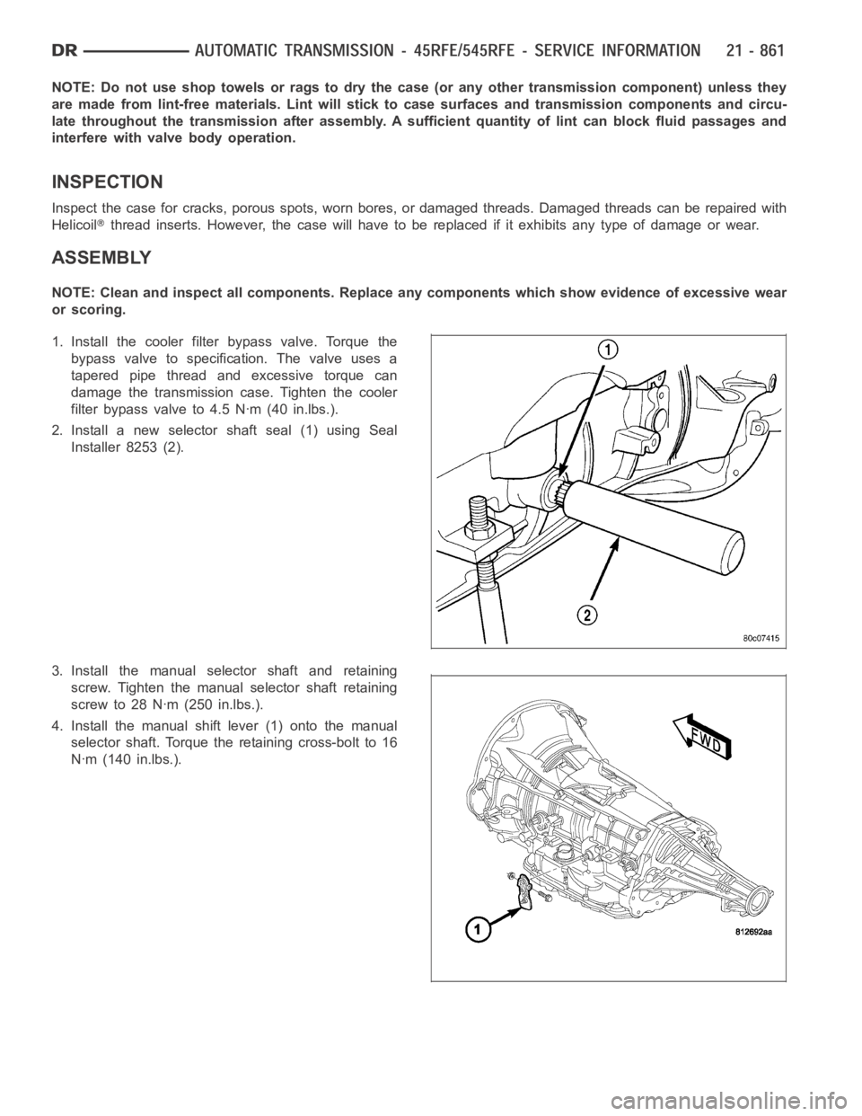
1. Install the cooler filter bypass valve. Torque the
bypass valve to specification. The valve uses a
tapered pipe thread and excessive torque can
damage the transmission case. Tighten the cooler
filter bypass valve to 4.5 Nꞏm (40 in.lbs.).
2. Install a new selector shaft seal (1) using Seal
Installer 8253 (2).
3. Install the manual selector shaft and retaining
screw. Tighten the manual selector shaft retaining
screw to 28 Nꞏm (250 in.lbs.).
4. Install the manual shift lever (1) onto the manual
selector shaft. Torque the retaining cross-bolt to 16
Nꞏm (140 in.lbs.).
Page 3384 of 5267
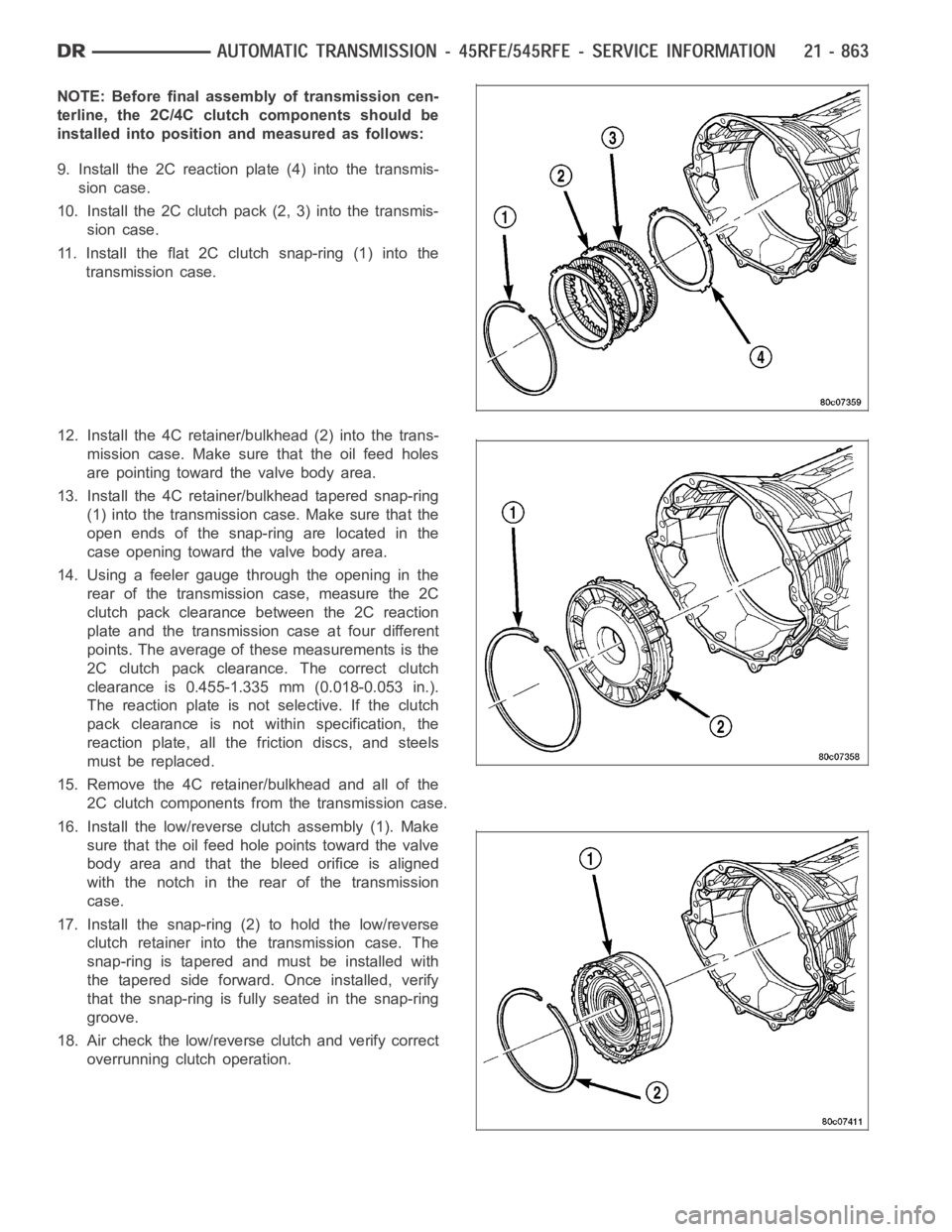
NOTE: Before final assembly of transmission cen-
terline, the 2C/4C clutch components should be
installed into position and measured as follows:
9. Install the 2C reaction plate (4) into the transmis-
sion case.
10. Install the 2C clutch pack (2, 3) into the transmis-
sion case.
11. Install the flat 2C clutchsnap-ring(1)intothe
transmission case.
12. Install the 4C retainer/bulkhead (2) into the trans-
mission case. Make sure that the oil feed holes
are pointing toward the valve body area.
13. Install the 4C retainer/bulkhead tapered snap-ring
(1) into the transmission case. Make sure that the
open ends of the snap-ring are located in the
case opening toward the valve body area.
14. Using a feeler gauge through the opening in the
rear of the transmission case, measure the 2C
clutch pack clearance between the 2C reaction
plate and the transmission case at four different
points. The average of these measurements is the
2C clutch pack clearance. The correct clutch
clearance is 0.455-1.335 mm (0.018-0.053 in.).
The reaction plate is not selective. If the clutch
pack clearance is not within specification, the
reaction plate, all the friction discs, and steels
must be replaced.
15. Remove the 4C retainer/bulkhead and all of the
2C clutch components from the transmission case.
16. Install the low/reverse clutch assembly (1). Make
sure that the oil feed hole points toward the valve
body area and that the bleed orifice is aligned
with the notch in the rear of the transmission
case.
17. Install the snap-ring (2) to hold the low/reverse
clutch retainer into the transmission case. The
snap-ring is tapered and must be installed with
the tapered side forward. Once installed, verify
that the snap-ring is fully seated in the snap-ring
groove.
18. Air check the low/reverse clutch and verify correct
overrunning clutch operation.
Page 3385 of 5267
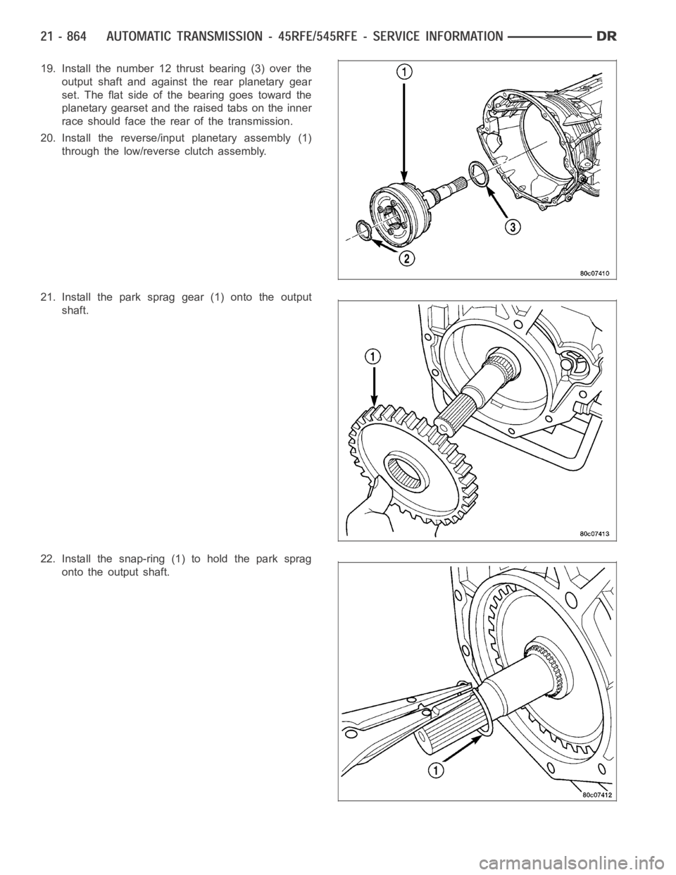
19. Install the number 12 thrust bearing (3) over the
output shaft and against the rear planetary gear
set. The flat side of the bearing goes toward the
planetary gearset and the raised tabs on the inner
race should face the rear of the transmission.
20. Install the reverse/input planetary assembly (1)
through the low/reverse clutch assembly.
21. Install the park sprag gear (1) onto the output
shaft.
22. Install the snap-ring (1) to hold the park sprag
onto the output shaft.
Page 3388 of 5267
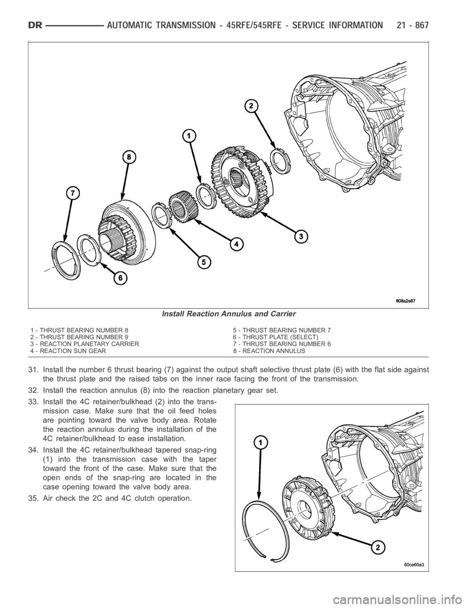
31. Install the number 6 thrust bearing (7) against the output shaft selective thrust plate (6) with the flat side against
the thrust plate and the raised tabs on the inner race facing the front of thetransmission.
32. Install the reaction annulus (8) into the reaction planetary gear set.
33. Install the 4C retainer/bulkhead (2) into the trans-
mission case. Make sure that the oil feed holes
are pointing toward the valve body area. Rotate
the reaction annulus during the installation of the
4C retainer/bulkhead to ease installation.
34. Install the 4C retainer/bulkhead tapered snap-ring
(1) into the transmission case with the taper
toward the front of the case. Make sure that the
open ends of the snap-ring are located in the
case opening toward the valve body area.
35. Air check the 2C and 4C clutch operation.
Install Reaction Annulus and Carrier
1 - THRUST BEARING NUMBER 8 5 - THRUST BEARING NUMBER 7
2 - THRUST BEARING NUMBER 9 6 - THRUST PLATE (SELECT)
3 - REACTION PLANETARY CARRIER 7 - THRUST BEARING NUMBER 6
4 - REACTION SUN GEAR 8 - REACTION ANNULUS
Page 3430 of 5267
FLUID AND FILTER
DIAGNOSIS AND TESTING
EFFECTS OF INCORRECT FLUID LEVEL
Alowfluidlevelallowsthepumptotakeinairalongwiththefluid.Airinthe fluid will cause fluid pressures to be
low and develop slower than normal. If the transmission is overfilled, thegears churn the fluid into foam. This aer-
ates the fluid and causing the same conditions occurring with a low level. In either case, air bubbles cause fluid
overheating, oxidation, and varnish buildup which interferes with valveand clutch operation. Foaming also causes
fluid expansion which can result in fluid overflow from the transmission vent or fill tube. Fluid overflow can easily be
mistaken for a leak if inspection is not careful.
CAUSES OF BURNT FLUID
Burnt, discolored fluid is a result of overheating which has three primarycauses.
1. Internal clutch slippage, usually caused by low line pressure, inadequate clutch apply pressure, or clutch seal
failure.
2. A result of restricted fluid flow through the main and/or auxiliary cooler. This condition is usually the result of a
faulty or improperly installed drainback valve, a damaged oil cooler, or severe restrictions in the coolers and lines
caused by debris or kinked lines.
3. Heavy duty operation with a vehicle not properly equipped for this type of operation. Trailer towing or similar high
load operation will overheat the transmission fluid if the vehicle is improperly equipped. Such vehicles should
have an auxiliary transmission fluid cooler, a heavy duty cooling system,and the engine/axle ratio combination
needed to handle heavy loads.
FLUID CONTAMINATION
Transmission fluid contamination is generally a result of:
adding incorrect fluid
failure to clean dipstick and fill tube when checking level
engine coolant entering the fluid
internal failure that generates debris
overheat that generates sludge (fluid breakdown)
failure to replace contaminated converter after repair
The use of non-recommended fluids can result in transmission failure. Theusual results are erratic shifts, slippage,
abnormal wear and eventual failure due to fluid breakdown and sludge formation. Avoid this condition by using rec-
ommended fluids only.
The dipstick cap and fill tube should be wiped clean before checking fluid level. Dirt, grease and other foreign mate-
rial on the cap and tube could fall into the tube if not removed beforehand. Take the time to wipe the cap and tube
clean before withdrawing the dipstick.
Engine coolant in the transmission fluid is generally caused by a cooler malfunction. The only remedy is to replace
the radiator as the cooler in the radiator is not a serviceable part. If coolant has circulated through the transmission,
an overhaul is necessary.
The torque converter should also be replaced whenever a failure generatessludge and debris. This is necessary
because normal converter flushing procedures will not remove all contaminants.
STANDARD PROCEDURE
FLUID LEVEL CHECK
Low fluid level can cause a variety of conditions because it allows the pumpto take in air along with the fluid. As
in any hydraulic system, air bubbles make the fluid spongy, therefore, pressures will be low and build up slowly.
Improper filling can also raise the fluid level too high. When the transmssion has too much fluid, the geartrain
churns up foam and cause the same conditions which occur with a low fluid level.