Page 2911 of 5267
MECHANISM-SHIFT
DESCRIPTION ............................... 536
OPERATION ................................. 536
SOLENOID
DESCRIPTION ............................... 537
OPERATION ................................. 538
ASSEMBLY-TRANSMISSION SOLENOID/
PRESSURE SWITCH
DESCRIPTION ............................... 539
OPERATION ................................. 539
REMOVAL ................................... 540
INSTALLATION .............................. 541
CONVERTER-TORQUE
DESCRIPTION ............................... 542
OPERATION ................................. 546
REMOVAL ................................... 548
INSTALLATION .............................. 549
SWITCH-TOW/HAUL OVERDRIVE
DESCRIPTION ............................... 550
OPERATION ................................. 550REMOVAL ................................... 550
INSTALLATION .............................. 551
RELAY-TRANSMISSION CONTROL
DESCRIPTION ............................... 552
OPERATION ................................. 552
SENSOR-TRANSMISSION RANGE
DESCRIPTION ............................... 553
OPERATION ................................. 553
REMOVAL ................................... 554
INSTALLATION .............................. 555
SENSOR-TRANSMISSION TEMPERATURE
DESCRIPTION ............................... 556
OPERATION ................................. 556
BODY-VALVE
DESCRIPTION ............................... 557
OPERATION ................................. 558
REMOVAL ................................... 562
DISASSEMBLY .............................. 564
ASSEMBLY .................................. 571
INSTALLATION .............................. 578
Page 2915 of 5267
First 2.84 : 1
Second 1.57 : 1
Third 1.00 : 1
Overdrive 0.69 : 1
Reverse 2.21 : 1
FIRST GEAR POWERFLOW
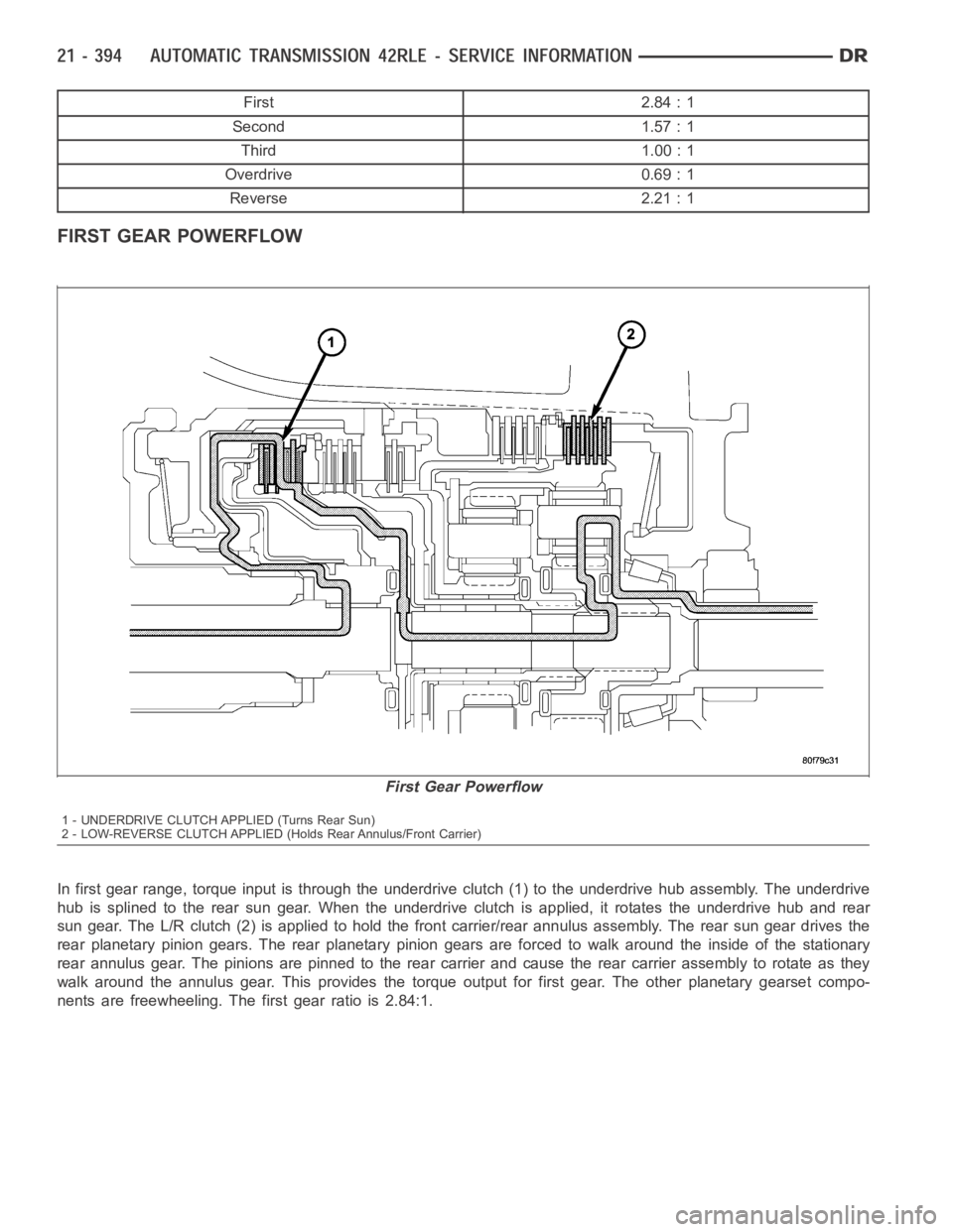
In first gear range, torque input is through the underdrive clutch (1) to the underdrive hub assembly. The underdrive
hub is splined to the rear sun gear. When the underdrive clutch is applied, it rotates the underdrive hub and rear
sun gear. The L/R clutch (2) is applied to hold the front carrier/rear annulus assembly. The rear sun gear drives the
rear planetary pinion gears. The rear planetary pinion gears are forced towalk around the inside of the stationary
rear annulus gear. The pinions are pinned to the rear carrier and cause the rear carrier assembly to rotate as they
walk around the annulus gear. This provides the torque output for first gear. The other planetary gearset compo-
nents are freewheeling. The first gear ratio is 2.84:1.
First Gear Powerflow
1 - UNDERDRIVE CLUTCH APPLIED (Turns Rear Sun)
2 - LOW-REVERSE CLUTCH APPLIED (Holds Rear Annulus/Front Carrier)
Page 3014 of 5267
FLUID AND FILTER
DIAGNOSIS AND TESTING
CAUSES OF BURNT FLUID
Burnt, discolored fluid is a result of overheating which has two primary causes.
1. A result of restricted fluid flow through the main and/or auxiliary cooler. This condition is usually the result of a
faulty or improperly installed drainback valve, a damaged oil cooler, or severe restrictions in the coolers and lines
caused by debris or kinked lines.
2. Heavy duty operation with a vehicle not properly equipped for this type of operation. Trailer towing or similar high
load operation will overheat the transmission fluid if the vehicle is improperly equipped. Such vehicles should
have an auxiliary transmission fluid cooler, a heavy duty cooling system,and the engine/axle ratio combination
needed to handle heavy loads.
EFFECTS OF INCORRECT FLUID LEVEL
Alowfluidlevelallowsthepumptotakeinairalongwiththefluid.Airinthe fluid will cause fluid pressures to be
low and develop slower than normal. If the transmission is overfilled, thegears churn the fluid into foam. This aer-
ates the fluid and causing the same conditions occurring with a low level. In either case, air bubbles cause fluid
overheating, oxidation, and varnish buildup which interferes with valveand clutch operation. Foaming also causes
fluid expansion which can result in fluid overflow from the transmission vent or fill tube. Fluid overflow can easily be
mistaken for a leak if inspection is not careful.
FLUID CONTAMINATION
Transmission fluid contamination is generally a result of:
adding incorrect fluid
failure to clean dipstick and fill tube when checking level
engine coolant entering the fluid
internal failure that generates debris
overheat that generates sludge (fluid breakdown)
failure to replace contaminated converter after repair
The use of non-recommended fluids can result in transmission failure. Theusual results are erratic shifts, slippage,
abnormal wear and eventual failure due to fluid breakdown and sludge formation. Avoid this condition by using rec-
ommended fluids only.
The dipstick cap and fill tube should be wiped clean before checking fluid level. Dirt, grease and other foreign mate-
rial on the cap and tube could fall into the tube if not removed beforehand. Take the time to wipe the cap and tube
clean before withdrawing the dipstick.
Engine coolant in the transmission fluid is generally caused by a cooler malfunction. The only remedy is to replace
the radiator as the cooler in the radiator is not a serviceable part. If coolant has circulated through the transmission,
an overhaul is necessary.
The torque converter should also be replaced whenever a failure generatessludge and debris. This is necessary
because normal converter flushing procedures will not remove all contaminants.
STANDARD PROCEDURE
FLUID LEVEL CHECK
The transmission sump has a dipstick to check oil similar to most automatictransmissions. It is located on the left
side of the engine. Be sure to wipe all dirt from dipstick handle before removing.
The torque converter fills in both the PARK and NEUTRAL positions. Place the selector lever in PARK to be sure
that the fluid level check is accurate.The engine should be running at idle speed for at least one minute, with
the vehicle on level ground.At normal operating temperature (approximately 82° C or 180° F), the fluidlevel is
correct if it is in the HOT region (cross-hatched area) on the oil level indicator. The fluid level should be in COLD
region at 21° C (70° F) fluid temperature. Adjust fluid level as necessary.Use only Mopar
ATF+4, Automatic Trans-
mission Fluid.
Page 3038 of 5267
25. Install OD reaction plate waved snap ring (1).
26. Install the OD/Reverse reaction plate (1) with
largestepdown(towardsODclutchpack).
27. Install OD reaction plate flat snap ring (3).
Page 3039 of 5267
28. Measure OD clutch pack clearance. Set up Dial
Indicator C-3339 (1) on top of the OD/Reverse
reaction plate (2).
29. Zero dial indicator and apply 30 psi (206 kPa) air
pressure to the overdrive clutch hose on Pressure
Fixture 8391. Measure and record OD clutch pack
measurement in four (4) places, 90° apart.
30. Take average of four measurements and compare
with OD clutch pack clearance specification.The
overdrive (OD) clutch pack clearance is
1.07-3.25 mm (0.042-0.128 in.).
If not within specifications,theclutchisnotassembled
properly. There is no adjustment for the OD clutch
clearance.
31. Install reverse clutch pack (two fibers/one steel)
(1, 2).
32. Install reverse clutch reaction plate (1) with the
flat side down towards reverse clutch.
Page 3068 of 5267
TURBINE
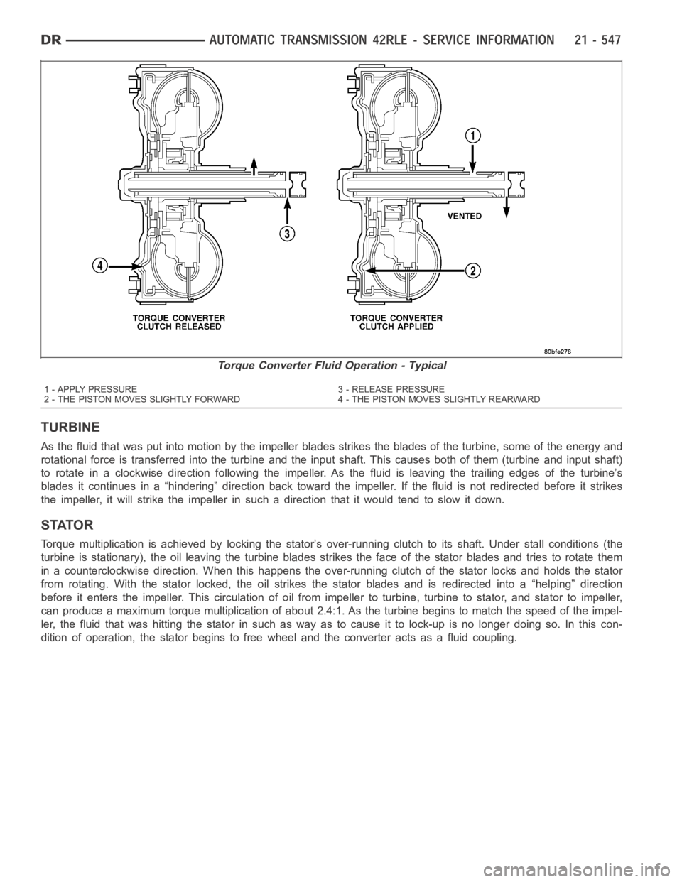
As the fluid that was put into motion bythe impeller blades strikes the blades of the turbine, some of the energy and
rotational force is transferred into the turbine and the input shaft. Thiscauses both of them (turbine and input shaft)
to rotate in a clockwise direction following the impeller. As the fluid is leaving the trailing edges of the turbine’s
blades it continues in a “hindering” direction back toward the impeller. If the fluid is not redirected before it strikes
the impeller, it will strike the impeller in such a direction that it would tend to slow it down.
STATOR
Torque multiplication is achieved by locking the stator’s over-running clutch to its shaft. Under stall conditions (the
turbine is stationary), the oil leaving the turbine blades strikes the face of the stator blades and tries to rotate them
in a counterclockwise direction. When this happens the over-running clutch of the stator locks and holds the stator
from rotating. With the stator locked, the oil strikes the stator blades and is redirected into a “helping” direction
before it enters the impeller. This circulation of oil from impeller to turbine, turbine to stator, and stator to impeller,
can produce a maximum torque multiplicationofabout2.4:1.Astheturbinebegins to match the speed of the impel-
ler, the fluid that was hitting the stator in such as way as to cause it to lock-up is no longer doing so. In this con-
dition of operation, the stator begins to free wheel and the converter actsas a fluid coupling.
Torque Converter Fluid Operation - Typical
1 - APPLY PRESSURE 3 - RELEASE PRESSURE
2 - THE PISTON MOVES SLIGHTLY FORWARD 4 - THE PISTON MOVES SLIGHTLY REARWARD
Page 3071 of 5267
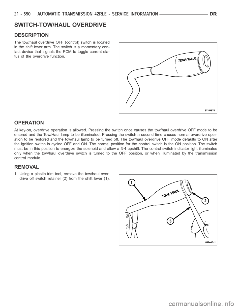
SWITCH-TOW/HAUL OVERDRIVE
DESCRIPTION
The tow/haul overdrive OFF (control) switch is located
in the shift lever arm. The switch is a momentary con-
tact device that signals the PCM to toggle current sta-
tus of the overdrive function.
OPERATION
At key-on, overdrive operation is allowed. Pressing the switch once causes the tow/haul overdrive OFF mode to be
entered and the Tow/Haul lamp to be illuminated. Pressing the switch a second time causes normal overdrive oper-
ationtoberestoredandthetow/haullamptobeturnedoff.Thetow/hauloverdrive OFF mode defaults to ON after
the ignition switch is cycled OFF and ON. The normal position for the control switch is the ON position. The switch
must be in this position to energize the solenoid and allow a 3-4 upshift. The control switch indicator light illuminates
only when the tow/haul overdrive switch is turned to the OFF position, or when illuminated by the transmission
control module.
REMOVAL
1. Using a plastic trim tool, remove the tow/haul over-
drive off switch retainer (2) from the shift lever (1).
Page 3072 of 5267
2. Pull the switch (2) outwards to release it from the
connector in the lever (1)
INSTALLATION
NOTE: There is enough slack in the wire to pull out the connector from the lever.
1. Pull the connector (2) out of the lever (1) just
enough to grasp it.
CAUTION: Be careful not to bend the pins on the
tow/haul overdrive off switch. Use care when
installing the switch, as it is not indexed, and can
be accidentally installed incorrectly.
2. Install the tow/haul overdrive off switch (3) into the
connector (2)
3. Push the tow/haul overdrive off switch (3) and wir-
ing into the shift lever (1).
4. Install the tow/haul overdrive off switch retainer
onto the shift lever.