2006 DODGE RAM SRT-10 tow
[x] Cancel search: towPage 2166 of 5267
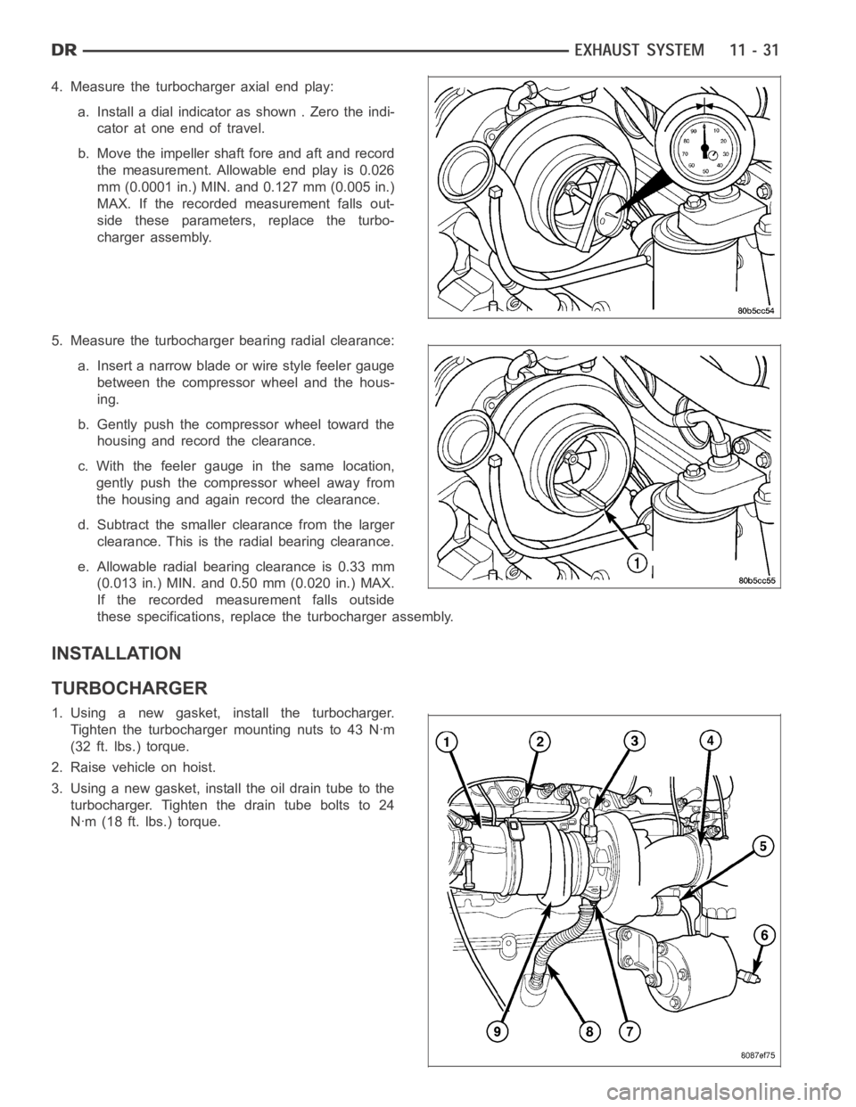
4. Measure the turbocharger axial end play:
a. Install a dial indicator as shown . Zero the indi-
cator at one end of travel.
b. Move the impeller shaft fore and aft and record
the measurement. Allowable end play is 0.026
mm (0.0001 in.) MIN. and 0.127 mm (0.005 in.)
MAX. If the recorded measurement falls out-
side these parameters, replace the turbo-
charger assembly.
5. Measure the turbocharger bearing radial clearance:
a. Insert a narrow blade or wire style feeler gauge
between the compressor wheel and the hous-
ing.
b. Gently push the compressor wheel toward the
housing and record the clearance.
c. With the feeler gauge in the same location,
gently push the compressor wheel away from
the housing and again record the clearance.
d. Subtract the smaller clearance from the larger
clearance. This is the radial bearing clearance.
e. Allowable radial bearing clearance is 0.33 mm
(0.013 in.) MIN. and 0.50 mm (0.020 in.) MAX.
If the recorded measurement falls outside
these specifications, replace the turbocharger assembly.
INSTALLATION
TURBOCHARGER
1. Using a new gasket, install the turbocharger.
Tighten the turbocharger mounting nuts to 43 Nꞏm
(32 ft. lbs.) torque.
2. Raise vehicle on hoist.
3. Using a new gasket, install the oil drain tube to the
turbocharger. Tighten the drain tube bolts to 24
Nꞏm (18 ft. lbs.) torque.
Page 2174 of 5267
FRAME & BUMPERS
TABLE OF CONTENTS
page page
FRAMES & BUMPERS
SPECIFICATIONS
TORQUE .................................... 2
FRONT AIR DAM
REMOVAL ..................................... 3
INSTALLATION ................................ 3
FRONT BUMPER
REMOVAL ..................................... 4
INSTALLATION ................................ 4
FRONT FASCIA
REMOVAL ..................................... 5
INSTALLATION ................................ 6
REAR BUMPER
REMOVAL ..................................... 7
INSTALLATION ................................ 8
FASCIA-FRONT SRT-10
REMOVAL ..................................... 9
INSTALLATION ................................ 11
FASCIA-REAR SRT-10
REMOVAL .................................... 14
INSTALLATION ............................... 15
FRAME
WARNING
WARNINGS ................................ 17
STANDARD PROCEDURE
HYDROFORM FENDER RAIL REPAIR ........ 18REAR FRAME H-SECTION REPLACEMENT . . . 27
SPECIFICATIONS
WELD PROCESS ........................... 33
FRAME DIMENSIONS ....................... 34
TORQUE ................................... 45
FRONT CROSSMEMBER
REMOVAL .................................... 46
INSTALLATION ............................... 48
FRONT SKID PLATE
REMOVAL .................................... 50
INSTALLATION ............................... 51
FRONT TOW HOOK ASSEMBLY
REMOVAL .................................... 52
INSTALLATION ............................... 53
TRANSMISSION CROSSMEMBER
REMOVAL .................................... 54
INSTALLATION ............................... 56
TRAILER HITCH
REMOVAL .................................... 58
INSTALLATION ............................... 60
TRANSFER CASE SKID PLATE
REMOVAL .................................... 62
INSTALLATION ............................... 63
Page 2225 of 5267
FRONT TOW HOOK ASSEMBLY
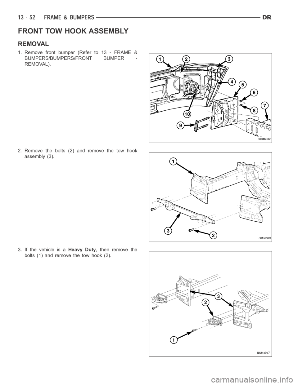
REMOVAL
1. Remove front bumper (Refer to 13 - FRAME &
BUMPERS/BUMPERS/FRONT BUMPER -
REMOVAL).
2. Remove the bolts (2) and remove the tow hook
assembly (3).
3. If the vehicle is aHeavy Duty, then remove the
bolts (1) and remove the tow hook (2).
Page 2226 of 5267
INSTALLATION
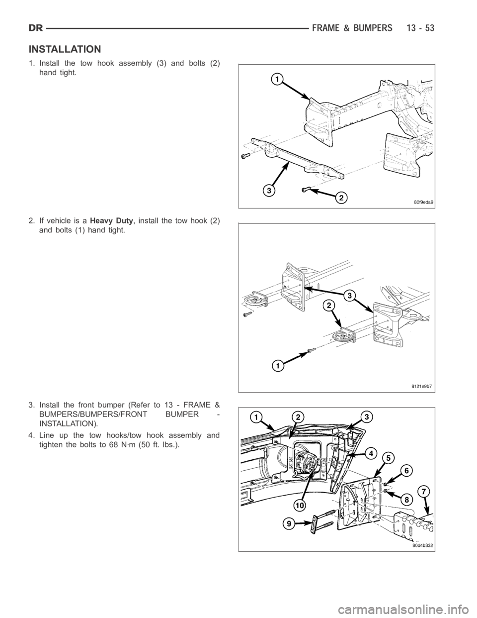
1. Install the tow hook assembly (3) and bolts (2)
hand tight.
2. If vehicle is aHeavy Duty, install the tow hook (2)
and bolts (1) hand tight.
3. Install the front bumper (Refer to 13 - FRAME &
BUMPERS/BUMPERS/FRONT BUMPER -
INSTALLATION).
4. Line up the tow hooks/tow hook assembly and
tighten the bolts to 68 Nꞏm (50 ft. lbs.).
Page 2242 of 5267

8. Connect other end of jumper wire to positive side of battery.
9. Connect one end of a second jumper wire to remaining injector terminal.
CAUTION: Powering an injector for more than a few seconds will permanentlydamage the injector.
10. Momentarily touch other end of jumper wire to negative terminal of battery for no more than a few seconds.
11. Place a rag or towel below fuel line quick-connect fitting at fuel rail.
12. Disconnect quick-connect fitting at fuel rail. Refer to Quick-Connect Fittings.
13. Return fuel pump relay to PDC.
14. One or more Diagnostic Trouble Codes (DTC’s) may have been stored in PCMmemory due to fuel pump relay
removal. The DRB
scantoolmustbeusedtoeraseaDTC.
STANDARD PROCEDURE - DRAINING FUEL TANK - EXCEPT DIESEL
WARNING: The fuel system may be under constant fuel pressure even with the engine off. This pressure
must be released before servicing fuel tank.
Two different procedures may be used to drain fuel tank: through the fuel fill fitting on tank, or using a diagnostic
scan tool to activate the fuel pump relay. Due to a one-way check valve installed into the fuel fill opening fitting at
the tank, the tank cannot be drained conventionally at the fill cap.
The quickest draining procedure involves removing the rubber fuel fill hose at the fuel tank.
As an alternative procedure, the electric fuel pump may be activated allowingtanktobedrainedatfuelrailcon-
nection. Refer to diagnostic scan tool for fuel pump activation procedures. Before disconnecting fuel line at fuel rail,
release fuel pressure. Refer to the Fuel System Pressure Release Procedure for procedures. Attach end of special
test hose tool number 6631 or 6539 at fuel rail disconnection (tool number 6631isusedon5/16”fuellineswhile
tool number 6539 is used on 3/8” fuel lines). Position opposite end of this hose tool to an approved gasoline drain-
ing station. Activate fuel pump and drain tank until empty.
If electric fuel pump is not operating, fuel must be drained through fuel fill fitting at tank. Refer to following proce-
dures.
1. Release fuel system pressure.
2. Raise vehicle.
3. Thoroughly clean area around fuel fill fitting and rubber fuel fill hoseat tank.
4. If vehicle is equipped with 4 doors and a 6 foot (short) box, remove left-rear tire/wheel.
5. Loosen clamp and disconnect rubber fuel fill hose at tank fitting. Usingan approved gas holding tank, drain fuel
tank through this fitting.
SPECIFICATIONS
FUEL SYSTEM PRESSURE
58 psi +/- 2 psi
TORQUE - EXCEPT DIESEL
DESCRIPTION N-m Ft. Lbs. In. Lbs.
Accelerator Pedal Bracket
Mounting12 - 105
Accelerator Pedal Position
Sensor Bracket-to-Battery
Tray Bolts3-30
Crankshaft Position
Sensor - 3.7L28 21 -
Crankshaft Position
Sensor - 4.7L28 21 -
Page 2254 of 5267
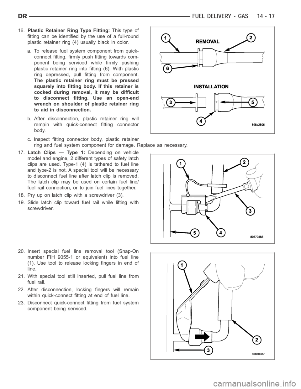
16.Plastic Retainer Ring Type Fitting:This type of
fitting can be identified by the use of a full-round
plastic retainer ring (4) usually black in color.
a. To release fuel systemcomponent from quick-
connect fitting, firmly push fitting towards com-
ponent being serviced while firmly pushing
plastic retainer ring into fitting (6). With plastic
ring depressed, pull fitting from component.
The plastic retainer ring must be pressed
squarely into fitting body. If this retainer is
cocked during removal, it may be difficult
to disconnect fitting. Use an open-end
wrench on shoulder of plastic retainer ring
to aid in disconnection.
b. After disconnection, plastic retainer ring will
remain with quick-connect fitting connector
body.
c. Inspect fitting connector body, plastic retainer
ring and fuel system component for damage. Replace as necessary.
17.Latch Clips — Type 1:Depending on vehicle
model and engine, 2 different types of safety latch
clips are used. Type-1 (4) is tethered to fuel line
and type-2 is not. A special tool will be necessary
to disconnect fuel line after latch clip is removed.
The latch clip may be used on certain fuel line/
fuel rail connection, or to join fuel lines together.
18. Pry up on latch clip with a screwdriver (3).
19. Slide latch clip toward fuel rail while lifting with
screwdriver.
20. Insert special fuel line removal tool (Snap-On
number FIH 9055-1 or equivalent) into fuel line
(1). Use tool to release locking fingers in end of
line.
21. With special tool still inserted, pull fuel line from
fuel rail.
22. After disconnection, locking fingers will remain
within quick-connect fitting at end of fuel line.
23. Disconnect quick-connect fitting from fuel system
component being serviced.
Page 2255 of 5267
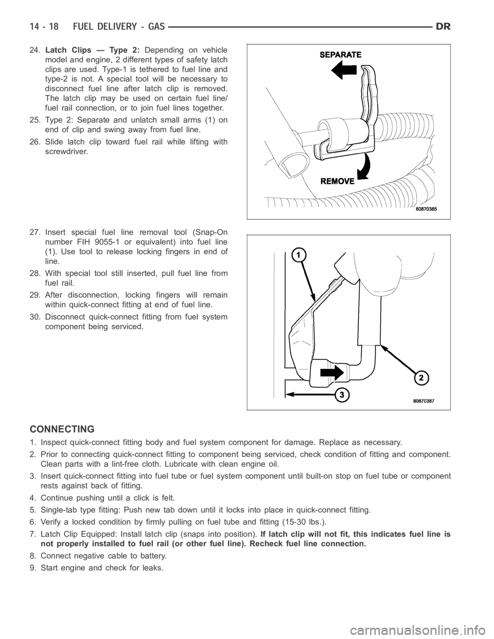
24.Latch Clips — Type 2:Depending on vehicle
model and engine, 2 different types of safety latch
clips are used. Type-1 is tethered to fuel line and
type-2 is not. A special tool will be necessary to
disconnect fuel line after latch clip is removed.
The latch clip may be used on certain fuel line/
fuel rail connection, or to join fuel lines together.
25. Type 2: Separate and unlatch small arms (1) on
end of clip and swing away from fuel line.
26. Slide latch clip toward fuel rail while lifting with
screwdriver.
27. Insert special fuel line removal tool (Snap-On
number FIH 9055-1 or equivalent) into fuel line
(1). Use tool to release locking fingers in end of
line.
28. With special tool still inserted, pull fuel line from
fuel rail.
29. After disconnection, locking fingers will remain
within quick-connect fitting at end of fuel line.
30. Disconnect quick-connect fitting from fuel system
component being serviced.
CONNECTING
1. Inspect quick-connect fitting body and fuel system component for damage. Replace as necessary.
2. Prior to connecting quick-connect fitting to component being serviced, check condition of fitting and component.
Clean parts with a lint-free cloth. Lubricate with clean engine oil.
3. Insert quick-connect fitting intofuel tube or fuel system component until built-on stop on fuel tube or component
rests against back of fitting.
4. Continue pushing until a click is felt.
5. Single-tab type fitting: Push new tab down until it locks into place in quick-connect fitting.
6. Verify a locked condition by firmly pulling on fuel tube and fitting (15-30 lbs.).
7. Latch Clip Equipped: Install latch clip (snaps into position).If latch clip will not fit, this indicates fuel line is
not properly installed to fuel rail (or other fuel line). Recheck fuel lineconnection.
8. Connect negative cable to battery.
9. Start engine and check for leaks.
Page 2332 of 5267
CABLE - THROTTLE CONTROL
REMOVAL
3.7L V-6
CAUTION: Be careful not to damage or kink cable core wire (within cable sheathing) while servicing accel-
erator pedal or throttle cable.
1. From inside vehicle, hold up accelerator pedal.
Remove plastic cable retainer (clip) and throttle
cable core wire from upper end of pedal arm. Plas-
tic cable retainer snaps into top of pedal arm.
2. Remove cable core wire at pedal arm.
3. From inside vehicle, remove metal clip holding
cable to dashpanel.
4. Remove air resonator box at throttle body.
5. Unsnap cable from dashpanel routing clip.
6. Remove cable housing from dash panel and pull
into engine compartment.
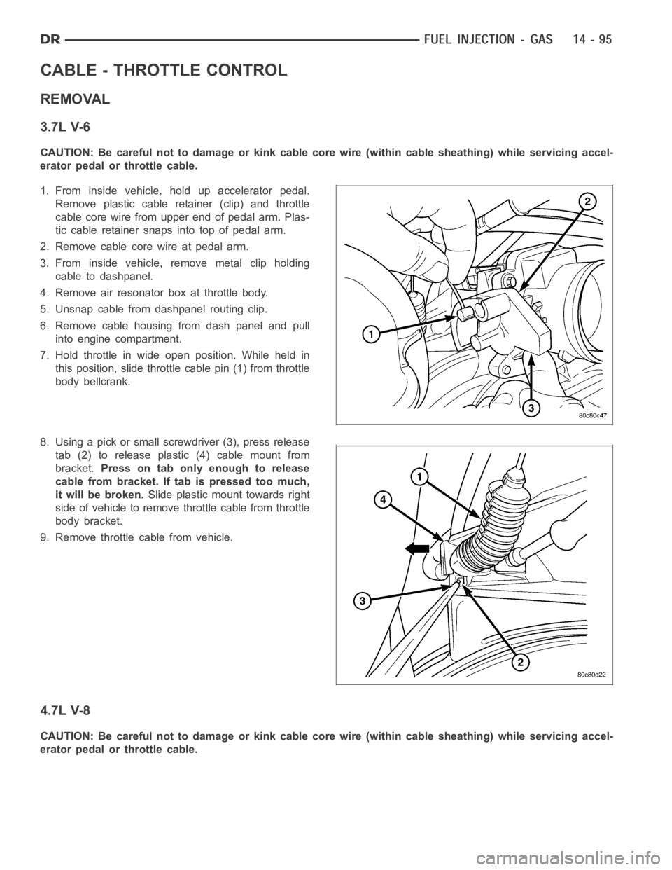
7. Hold throttle in wide open position. While held in
this position, slide throttle cable pin (1) from throttle
body bellcrank.
8. Using a pick or small screwdriver (3), press release
tab (2) to release plastic (4) cable mount from
bracket.Press on tab only enough to release
cable from bracket. If tab is pressed too much,
it will be broken.Slide plastic mount towards right
side of vehicle to remove throttle cable from throttle
body bracket.
9. Remove throttle cable from vehicle.
4.7L V-8
CAUTION: Be careful not to damage or kink cable core wire (within cable sheathing) while servicing accel-
erator pedal or throttle cable.