2006 DODGE RAM SRT-10 tow
[x] Cancel search: towPage 1914 of 5267
3. Place a shop towel around the fuel injectors to catch any fluid that may possibly be under pressure in the cyl-
inder head. Remove the fuel injectors (Refer to 14 - FUEL SYSTEM/FUEL INJECTION/FUEL INJECTOR -
REMOVAL).
4. With all injectors removed, rotatethe crankshaft using the crankshaftbarring tool (PN 7471–B).
5. Identify the fluid in the cylinders (coolant, fuel, oil, etc.).
6. Be sure all fluid has been removed from the cylinders.
7. Repair engine or components as necessary to prevent this problem from occurring again.
8. Squirt a small amount of engine oil into the cylinders to lubricate the walls. This will prevent damage on restart.
9. Install fuel injectors (Refer to 14 - FUEL SYSTEM/FUEL INJECTION/FUEL INJECTOR - INSTALLATION).
10. Drain engine oil. Remove and discard the oil filter (Refer to 9 - ENGINE/LUBRICATION/OIL FILTER -
REMOVAL).
11. Installthedrainplug.Tightentheplugto50Nꞏm(37ft.lbs.)torque.
12. Install a new oil filter (Refer to 9 - ENGINE/LUBRICATION/OIL FILTER - INSTALLATION).
13. Fill engine crankcase with the specified amount and grade of oil (Referto LUBRICATION & MAINTENANCE/
FLUID TYPES - SPECIFICATIONS).
14. Connect the negative cable(s) to the battery.
15. Start the engine and check for any leaks.
REMOVAL - ENGINE
1. Disconnect both battery negative cables.
2. Disconnect engine grid heater harness at grid
heater relays.
3. Disconnect electrical connections from rear of alter-
nator.
4. Recover A/C refrigerant. (Refer to 24 - HEATING &
AIR CONDITIONING/PLUMBING - STANDARD
PROCEDURE).
5. Raise vehicle on a hoist.
6. Drain engine coolant (Refer to 7 - COOLING -
STANDARD PROCEDURE).
7. Remove engine oil drain plug and drain engine oil.
8. Reinstall drain plug. Tighten to 50 Nꞏm (37 ft. lbs.)
torque.
9. Lower the vehicle.
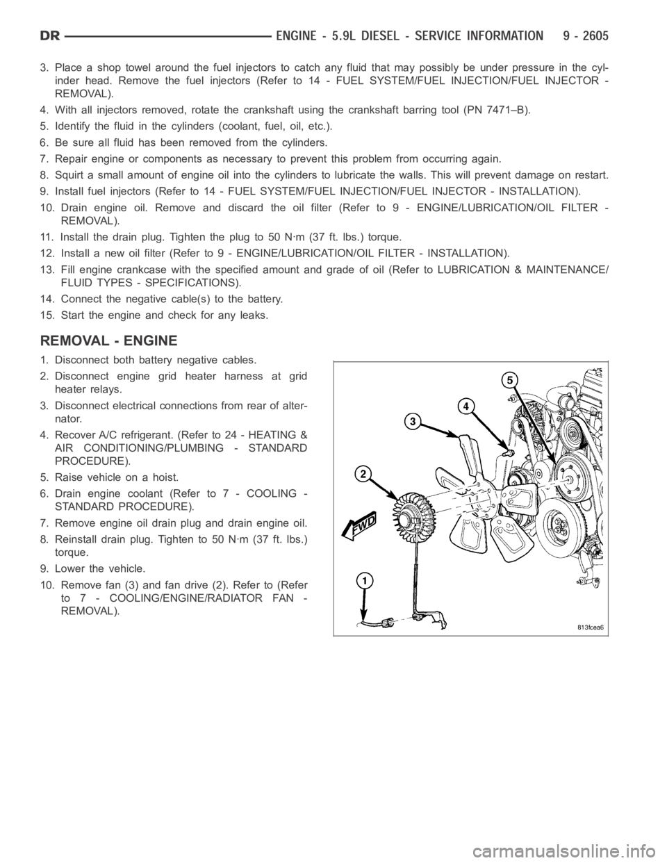
10. Remove fan (3) and fan drive (2). Refer to (Refer
to 7 - COOLING/ENGINE/RADIATOR FAN -
REMOVAL).
Page 1961 of 5267
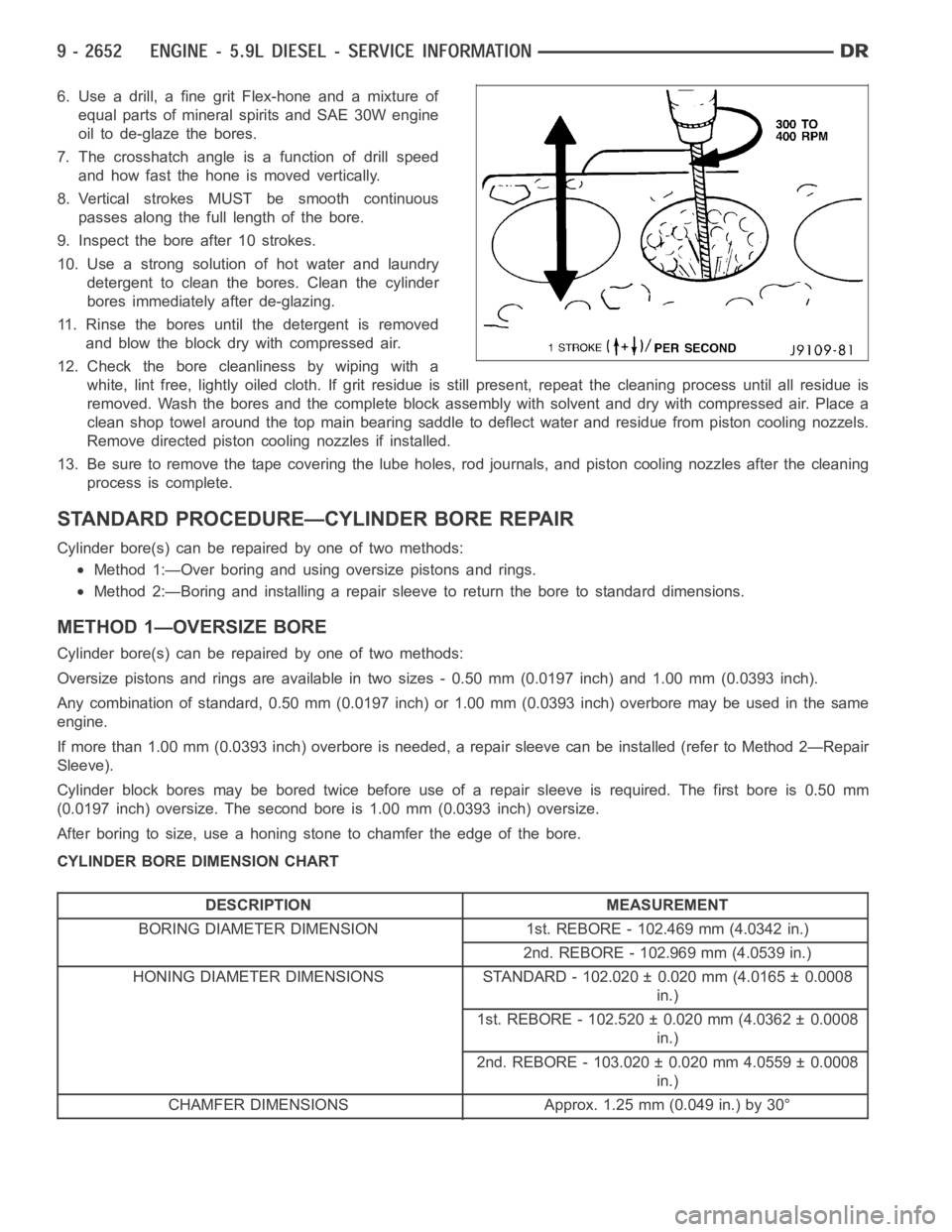
6. Use a drill, a fine grit Flex-hone and a mixture of
equal parts of mineral spirits and SAE 30W engine
oil to de-glaze the bores.
7. The crosshatch angle is a function of drill speed
and how fast the hone is moved vertically.
8. Vertical strokes MUST be smooth continuous
passes along the full length of the bore.
9. Inspect the bore after 10 strokes.
10. Use a strong solution of hot water and laundry
detergent to clean the bores. Clean the cylinder
bores immediately after de-glazing.
11. Rinse the bores until the detergent is removed
and blow the block dry with compressed air.
12. Check the bore cleanliness by wiping with a
white, lint free, lightly oiled cloth. If grit residue is still present, repeat the cleaning process until all residue is
removed. Wash the bores and the complete block assembly with solvent and dry with compressed air. Place a
clean shop towel around the top main bearing saddle to deflect water and residue from piston cooling nozzels.
Remove directed piston cooling nozzles if installed.
13. Be sure to remove the tape covering the lube holes, rod journals, and piston cooling nozzles after the cleaning
process is complete.
STANDARD PROCEDURE—CYLINDER BORE REPAIR
Cylinder bore(s) can be repaired by one of two methods:
Method 1:—Over boring and using oversize pistons and rings.
Method 2:—Boring and installing a repair sleeve to return the bore to standard dimensions.
METHOD 1—OVERSIZE BORE
Cylinder bore(s) can be repaired by one of two methods:
Oversize pistons and rings are available in two sizes - 0.50 mm (0.0197 inch) and 1.00 mm (0.0393 inch).
Any combination of standard, 0.50 mm (0.0197 inch) or 1.00 mm (0.0393 inch)overbore may be used in the same
engine.
If more than 1.00 mm (0.0393 inch) overbore is needed, a repair sleeve can beinstalled (refer to Method 2—Repair
Sleeve).
Cylinder block bores may be bored twice before use of a repair sleeve is required. The first bore is 0.50 mm
(0.0197 inch) oversize. The second bore is 1.00 mm (0.0393 inch) oversize.
After boring to size, use a honing stone to chamfer the edge of the bore.
CYLINDER BORE DIMENSION CHART
DESCRIPTION MEASUREMENT
BORING DIAMETER DIMENSION 1st. REBORE - 102.469 mm (4.0342 in.)
2nd. REBORE - 102.969 mm (4.0539 in.)
HONING DIAMETER DIMENSIONS STANDARD - 102.020 ± 0.020 mm (4.0165 ± 0.0008
in.)
1st. REBORE - 102.520 ± 0.020 mm (4.0362 ± 0.0008
in.)
2nd. REBORE - 103.020 ± 0.020 mm 4.0559 ± 0.0008
in.)
CHAMFER DIMENSIONS Approx. 1.25 mm (0.049 in.) by 30°
Page 1979 of 5267
SEAL - CRANKSHAFT OIL - REAR
REMOVAL
1. Disconnect the battery negative cables.
2. Remove the transmission and transfer case (if
equipped).
3. Remove the clutch cover and disc (if manual trans-
mission equipped) (Refer to 6 - CLUTCH/CLUTCH
DISC - REMOVAL).
4. Remove the flywheel or converter drive plate.
5. Remove the flywheel adapter plate.
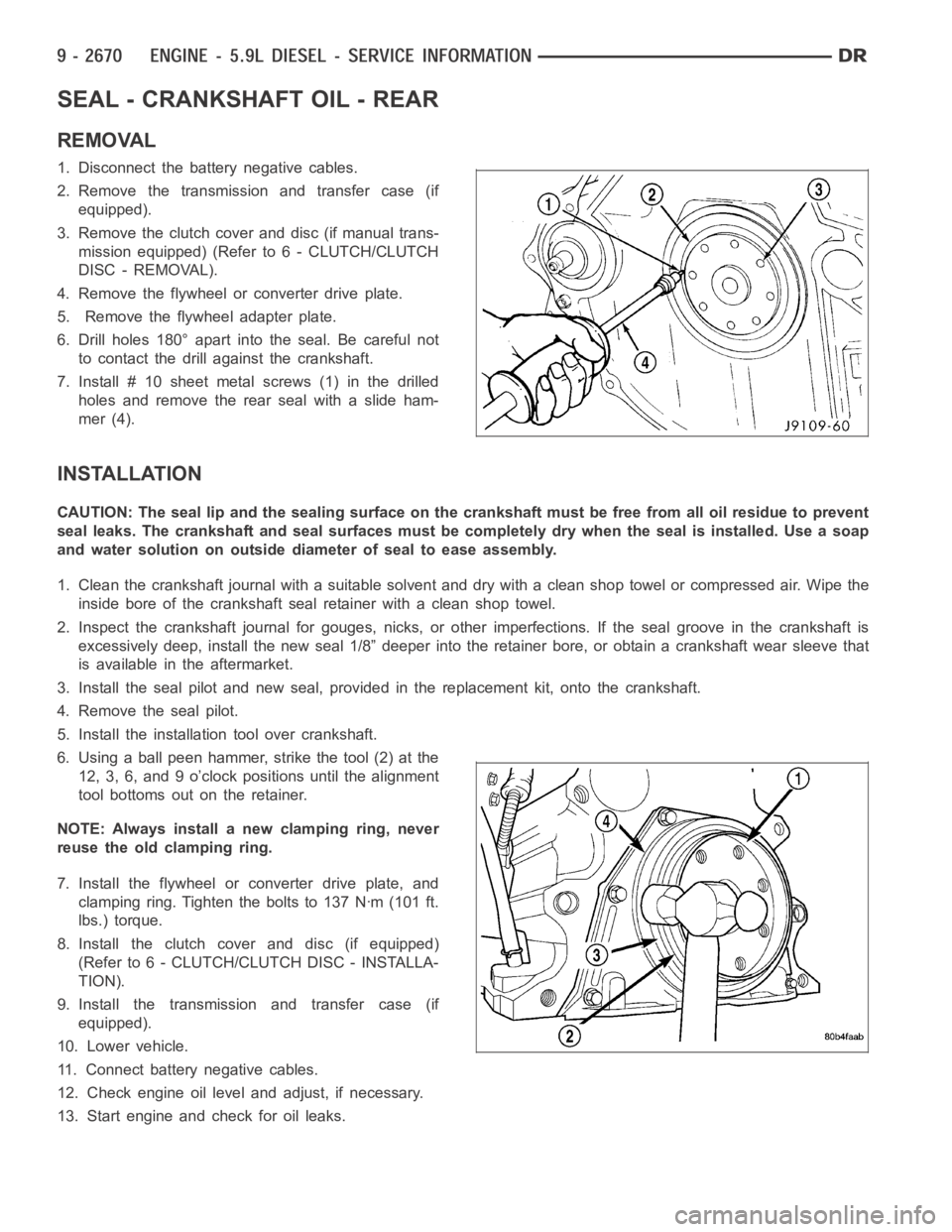
6. Drill holes 180° apart into the seal. Be careful not
to contact the drill against the crankshaft.
7. Install # 10 sheet metalscrews (1) in the drilled
holes and remove the rear seal with a slide ham-
mer (4).
INSTALLATION
CAUTION: The seal lip and the sealing surface on the crankshaft must be freefrom all oil residue to prevent
seal leaks. The crankshaft and seal surfaces must be completely dry when the seal is installed. Use a soap
and water solution on outside diameter of seal to ease assembly.
1. Clean the crankshaft journal with a suitable solvent and dry with a cleanshop towel or compressed air. Wipe the
inside bore of the crankshaft seal retainer with a clean shop towel.
2. Inspect the crankshaft journal forgouges, nicks, or other imperfections. If the seal groove in the crankshaft is
excessively deep, install the new seal 1/8” deeper into the retainer bore,or obtain a crankshaft wear sleeve that
is available in the aftermarket.
3. Install the seal pilot and new seal, provided in the replacement kit, onto the crankshaft.
4. Remove the seal pilot.
5. Install the installation tool over crankshaft.
6. Using a ball peen hammer, strike the tool (2) at the
12, 3, 6, and 9 o’clock positions until the alignment
tool bottoms out on the retainer.
NOTE: Always install a new clamping ring, never
reuse the old clamping ring.
7. Install the flywheel or converter drive plate, and
clamping ring. Tighten the bolts to 137 Nꞏm (101 ft.
lbs.) torque.
8. Install the clutch cover and disc (if equipped)
(Refer to 6 - CLUTCH/CLUTCH DISC - INSTALLA-
TION).
9. Install the transmission and transfer case (if
equipped).
10. Lower vehicle.
11. Connect battery negative cables.
12. Check engine oil level and adjust, if necessary.
13. Start engine and check for oil leaks.
Page 1982 of 5267
TAPPETS - VALVE
REMOVAL
NOTE: This procedure requires use of Miller Tool
8502 Tappet Replacement Kit.
1. Remove camshaft (Refer to 9 - ENGINE/ENGINE
BLOCK/CAMSHAFT & BEARINGS (IN BLOCK) -
REMOVAL).
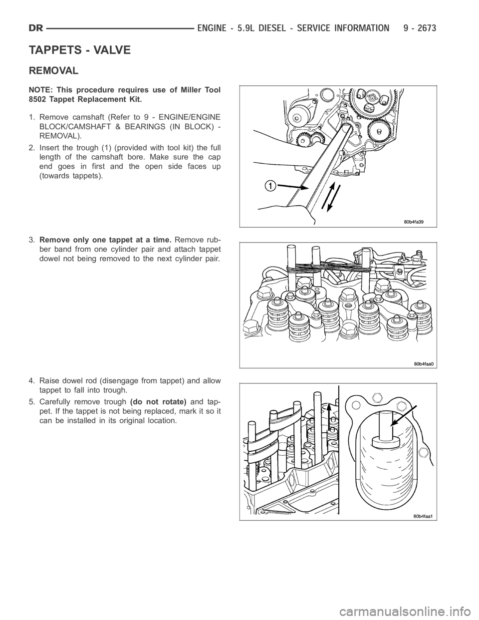
2. Insert the trough (1) (provided with tool kit) the full
length of the camshaft bore. Make sure the cap
end goes in first and the open side faces up
(towards tappets).
3.Remove only one tappet at a time.Remove rub-
ber band from one cylinder pair and attach tappet
dowel not being removed to the next cylinder pair.
4. Raise dowel rod (disengage from tappet) and allow
tappet to fall into trough.
5. Carefully remove trough(do not rotate)and tap-
pet. If the tappet is not being replaced, mark it so it
can be installed in its original location.
Page 1983 of 5267
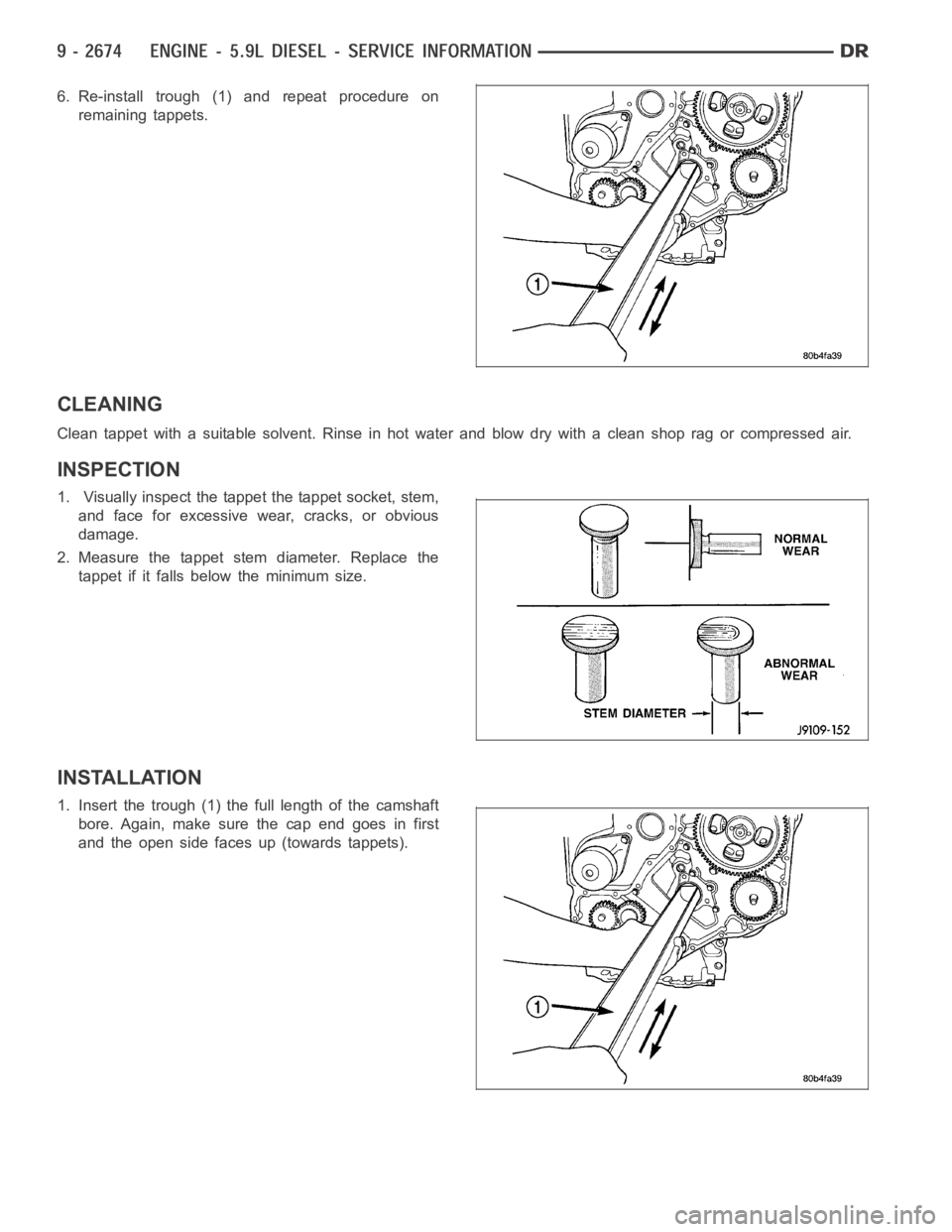
6. Re-install trough (1) and repeat procedure on
remaining tappets.
CLEANING
Clean tappet with a suitable solvent. Rinse in hot water and blow dry with a clean shop rag or compressed air.
INSPECTION
1. Visually inspect the tappet the tappet socket, stem,
and face for excessive wear, cracks, or obvious
damage.
2. Measure the tappet stem diameter. Replace the
tappet if it falls below the minimum size.
INSTALLATION
1. Insert the trough (1) the full length of the camshaft
bore. Again, make sure the cap end goes in first
and the open side faces up (towards tappets).
Page 1985 of 5267
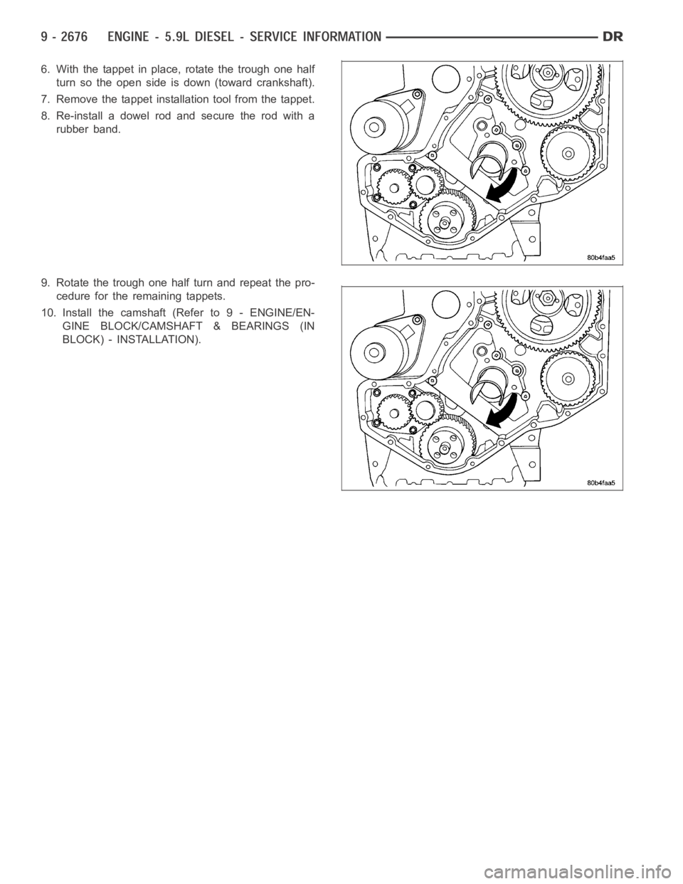
6. With the tappet in place, rotate the trough one half
turn so the open side is down (toward crankshaft).
7. Remove the tappet installation tool from the tappet.
8. Re-install a dowel rod and secure the rod with a
rubber band.
9. Rotate the trough one half turn and repeat the pro-
cedure for the remaining tappets.
10. Install the camshaft (Refer to 9 - ENGINE/EN-
GINE BLOCK/CAMSHAFT & BEARINGS (IN
BLOCK) - INSTALLATION).
Page 1989 of 5267
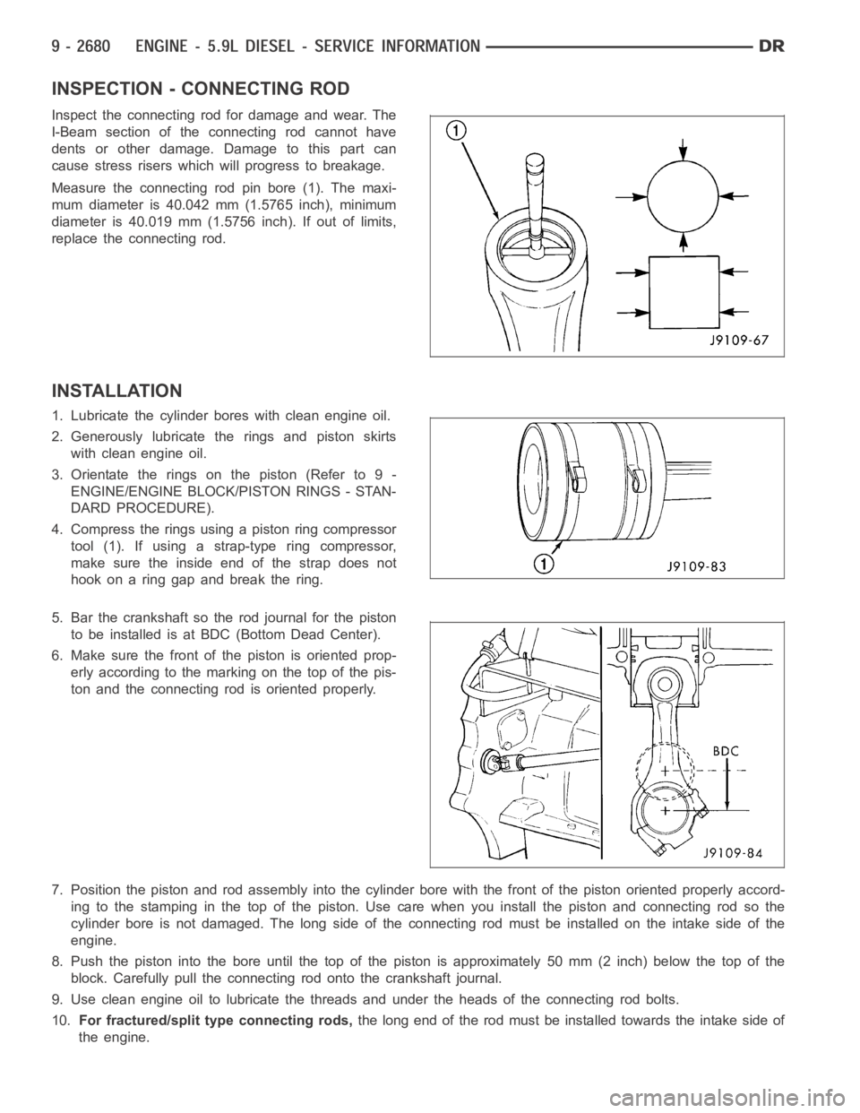
INSPECTION - CONNECTING ROD
Inspect the connecting rod for damage and wear. The
I-Beam section of the connecting rod cannot have
dents or other damage. Damage to this part can
cause stress risers which will progress to breakage.
Measure the connecting rod pin bore (1). The maxi-
mum diameter is 40.042 mm (1.5765 inch), minimum
diameter is 40.019 mm (1.5756 inch). If out of limits,
replace the connecting rod.
INSTALLATION
1. Lubricate the cylinder bores with clean engine oil.
2. Generously lubricate the rings and piston skirts
with clean engine oil.
3. Orientate the rings on the piston (Refer to 9 -
ENGINE/ENGINE BLOCK/PISTON RINGS - STAN-
DARD PROCEDURE).
4. Compress the rings using a piston ring compressor
tool(1).Ifusingastrap-typeringcompressor,
make sure the inside end of the strap does not
hook on a ring gap and break the ring.
5. Bar the crankshaft so the rod journal for the piston
to be installed is at BDC(Bottom Dead Center).
6. Make sure the front of the piston is oriented prop-
erly according to the marking on the top of the pis-
ton and the connecting rod is oriented properly.
7. Position the piston and rod assemblyinto the cylinder bore with the front of the piston oriented properly accord-
ing to the stamping in the top of the piston. Use care when you install the piston and connecting rod so the
cylinder bore is not damaged. The long side of the connecting rod must be installed on the intake side of the
engine.
8. Push the piston into the bore until the top of the piston is approximately50 mm (2 inch) below the top of the
block. Carefully pull the connecting rod onto the crankshaft journal.
9. Use clean engine oil to lubricate the threads and under the heads of the connecting rod bolts.
10.For fractured/split type connecting rods,thelongendoftherodmustbeinstalledtowardstheintakesideof
the engine.
Page 1990 of 5267
a. The connecting rod split/face mustface toward the same side as the piston notch feature on the skirt. The
split face will face toward the exhaust side of the engine if properly installed.
11. Install the rod cap and bolts to the connecting rod. Tighten the connecting rod bolts evenly in 3 steps.
Tighten the bolts to 30 Nꞏm (22 ft. lbs.) torque.
Tighten the bolts to 60 Nꞏm (44 ft. lbs.) torque.
Rotate 60° clockwise.
12. The crankshaft must rotate freely. Check for freedom of rotation as thecaps are installed. If the crankshaft does
not rotate freely, check the installation of the rod bearing and the bearingsize.
13. Measure the side clearance between the connecting rod and the crankshaft. DO NOT measure the clearance
between the cap and crankshaft.
14. Install J-jet piston cooling nozzles.
15. Install block stiffener. Torque to 43 Nꞏm (32 ft. lbs.).
16. Install the suction tube and oil pan (Refer to 9 - ENGINE/LUBRICATION/OIL PAN - INSTALLATION).
17. Install the cylinder head onto the engine (Refer to 9 - ENGINE/CYLINDERHEAD - INSTALLATION).
18. Install a new filter and fill the crankcase with new engine oil.Prefill the filter with clean oil.
19. Connect the battery negative cables and start engine.