Page 3474 of 5267
SWITCH-TOW/HAUL OVERDRIVE
DESCRIPTION
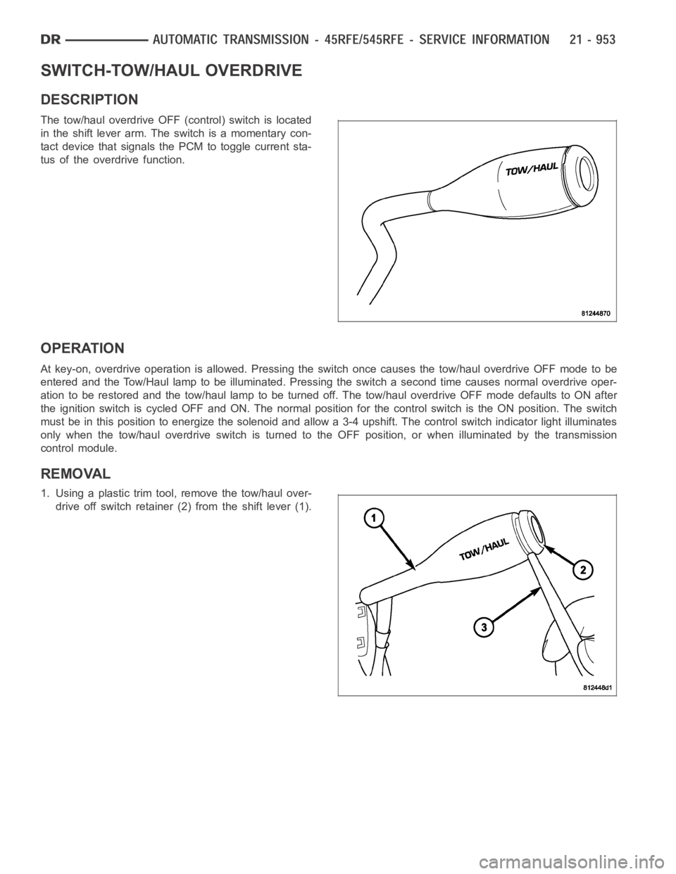
The tow/haul overdrive OFF (control) switch is located
in the shift lever arm. The switch is a momentary con-
tact device that signals the PCM to toggle current sta-
tus of the overdrive function.
OPERATION
At key-on, overdrive operation is allowed. Pressing the switch once causes the tow/haul overdrive OFF mode to be
entered and the Tow/Haul lamp to be illuminated. Pressing the switch a second time causes normal overdrive oper-
ationtoberestoredandthetow/haullamptobeturnedoff.Thetow/hauloverdrive OFF mode defaults to ON after
the ignition switch is cycled OFF and ON. The normal position for the control switch is the ON position. The switch
must be in this position to energize the solenoid and allow a 3-4 upshift. The control switch indicator light illuminates
only when the tow/haul overdrive switch is turned to the OFF position, or when illuminated by the transmission
control module.
REMOVAL
1. Using a plastic trim tool, remove the tow/haul over-
drive off switch retainer (2) from the shift lever (1).
Page 3475 of 5267
2. Pull the switch (2) outwards to release it from the
connector in the lever (1)
INSTALLATION
NOTE: There is enough slack in the wire to pull out the connector from the lever.
1. Pull the connector (2) out of the lever (1) just
enough to grasp it.
CAUTION: Be careful not to bend the pins on the
tow/haul overdrive off switch. Use care when
installing the switch, as it is not indexed, and can
be accidentally installed incorrectly.
2. Install the tow/haul overdrive off switch (3) into the
connector (2)
3. Push the tow/haul overdrive off switch (3) and wir-
ing into the shift lever (1).
4. Install the tow/haul overdrive off switch retainer
onto the shift lever.
Page 3476 of 5267
GEARTRAIN-PLANETARY
DESCRIPTION
The planetary geartrain is located behind the 4C retainer/bulkhead, toward the rear of the transmission. The plan-
etary geartrain consists of three primary assemblies:
Reaction (3, 4, 8).
Reaction Planetary Geartrain
1 - THRUST BEARING NUMBER 8 5 - THRUST BEARING NUMBER 7
2 - THRUST BEARING NUMBER 9 6 - THRUST PLATE (SELECT)
3 - REACTION PLANETARY CARRIER 7 - THRUST BEARING NUMBER 6
4 - REACTION SUN GEAR 8 - REACTION ANNULUS
Page 3479 of 5267
ASSEMBLY
NOTE: Clean and inspect all components. Replace any components which showevidence of excessive wear
or scoring.
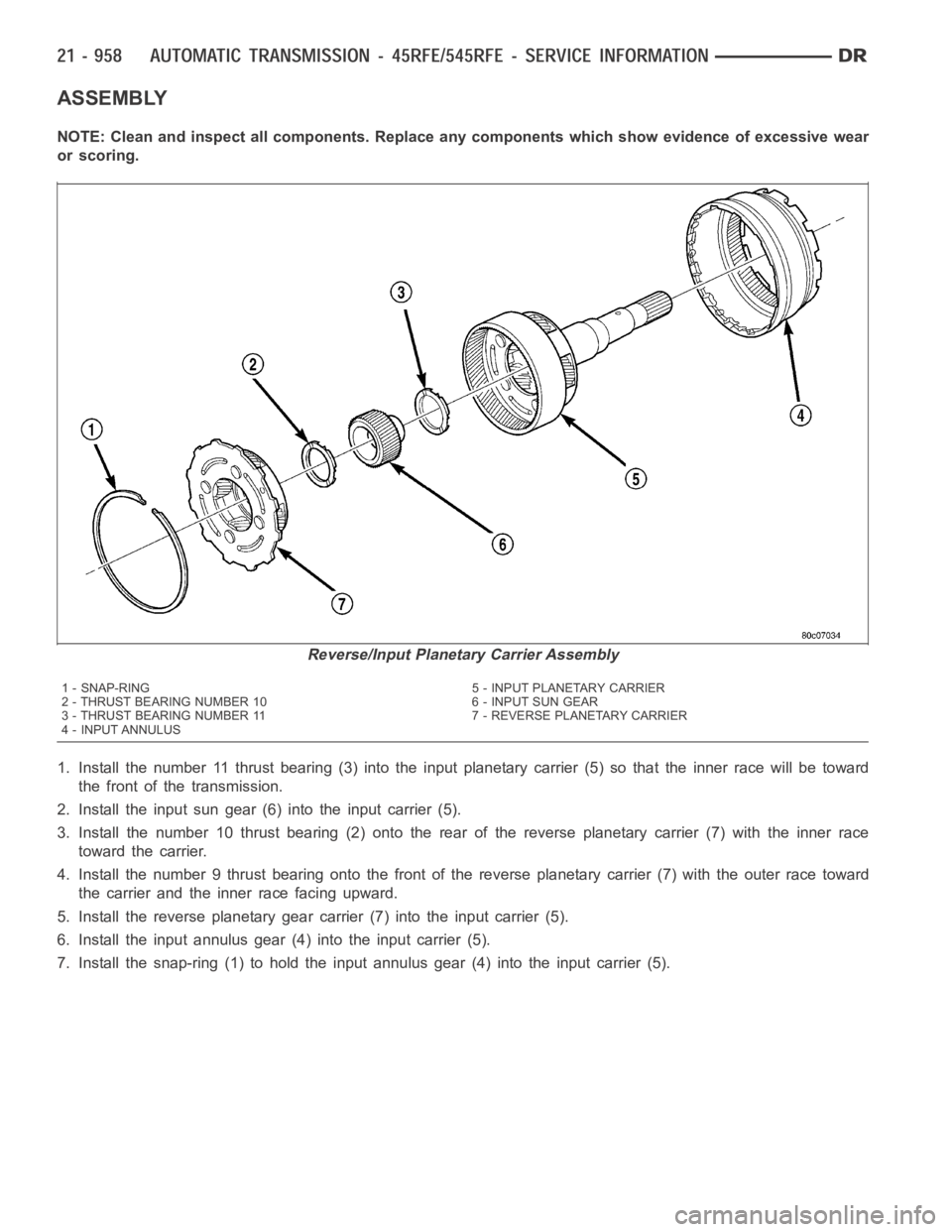
1. Install the number 11 thrust bearing (3) into the input planetary carrier (5) so that the inner race will be toward
the front of the transmission.
2. Install the input sun gear (6) into the input carrier (5).
3. Install the number 10 thrust bearing (2) onto the rear of the reverse planetary carrier (7) with the inner race
toward the carrier.
4. Install the number 9 thrust bearing onto the front of the reverse planetary carrier (7) with the outer race toward
the carrier and the inner race facing upward.
5. Install the reverse planetary gear carrier (7) into the input carrier (5).
6. Install the input annulus gear (4) into the input carrier (5).
7. Install the snap-ring (1) to hold the input annulus gear (4) into the input carrier (5).
Reverse/Input Planetary Carrier Assembly
1 - SNAP-RING 5 - INPUT PLANETARY CARRIER
2 - THRUST BEARING NUMBER 10 6 - INPUT SUN GEAR
3 - THRUST BEARING NUMBER 11 7 - REVERSE PLANETARY CARRIER
4 - INPUT ANNULUS
Page 3486 of 5267
TURBINE
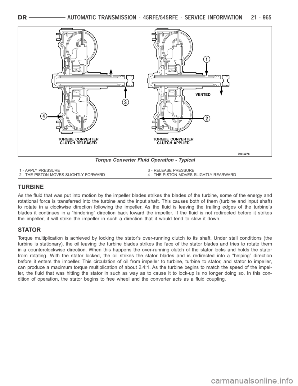
As the fluid that was put into motion bythe impeller blades strikes the blades of the turbine, some of the energy and
rotational force is transferred into the turbine and the input shaft. Thiscauses both of them (turbine and input shaft)
to rotate in a clockwise direction following the impeller. As the fluid is leaving the trailing edges of the turbine’s
blades it continues in a “hindering” direction back toward the impeller. If the fluid is not redirected before it strikes
the impeller, it will strike the impeller in such a direction that it would tend to slow it down.
STATOR
Torque multiplication is achieved by locking the stator’s over-running clutch to its shaft. Under stall conditions (the
turbine is stationary), the oil leaving the turbine blades strikes the face of the stator blades and tries to rotate them
in a counterclockwise direction. When this happens the over-running clutch of the stator locks and holds the stator
from rotating. With the stator locked, the oil strikes the stator blades and is redirected into a “helping” direction
before it enters the impeller. This circulation of oil from impeller to turbine, turbine to stator, and stator to impeller,
can produce a maximum torque multiplicationofabout2.4:1.Astheturbinebegins to match the speed of the impel-
ler, the fluid that was hitting the stator in such as way as to cause it to lock-up is no longer doing so. In this con-
dition of operation, the stator begins to free wheel and the converter actsas a fluid coupling.
Torque Converter Fluid Operation - Typical
1 - APPLY PRESSURE 3 - RELEASE PRESSURE
2 - THE PISTON MOVES SLIGHTLY FORWARD 4 - THE PISTON MOVES SLIGHTLY REARWARD
Page 3501 of 5267
CLEANING
Clean the valve housings, valves, plugs, springs, and separator plates with a standard parts cleaning solution only.
Do not use gasoline, kerosene, or any type of caustic solution.
Do not immerse any of the electrical components in cleaning solution. Clean the electrical components by wiping
them off with dry shop towels only.
Dry all except the electrical parts with compressed air. Make sure all passages are clean and free from obstructions.
Do not use rags or shop towels to dry or wipe off valve body components. Lint from these materials can
stick to valve body parts, interfere with valve operation, and clog filters and fluid passages.
Valve Body Components
1 - LOW/REVERSE ACCUMULATOR 6 - OVERDRIVE ACCUMULATOR
2 - LOW/REVERSE SWITCH VALVE 7 - UNDERDRIVE ACCUMULATOR
3 - UPPER VALVE BODY 8 - 4C ACCUMULATOR
4 - MANUAL VALVE 9 - 2C ACCUMULATOR
5 - SOLENOID SWITCH VALVE
Page 3553 of 5267
Theory of Operation
The Tow/haul Overdrive OFF (control) Switch is located in the shift lever arm. The switch is a momentary contact
device that signals the PCM to toggle current status of the overdrive function. At ignition on, overdrive operation is
allowed. Pressing the Tow/Haul Overdrive Off switch once causes the Tow/haul Overdrive OFF mode to be entered
and the Tow/Haul lamp to be illuminated. Pressing the switch a second time causes normal overdrive operation to
be restored and the Tow/haul lamp to be turned off. The Tow/haul Overdrive OFF mode defaults to ON after the
ignition switch is cycled OFF and ON. Thenormal position for the control switch is the ON position. The switch must
be in this position to energize the solenoid and allow a 3-4 upshift. The control switch indicator light illuminates only
when the Tow/haul Overdrive Off switch is turned to the OFF position, or when illuminated by the transmission con-
trol module.
When Monitored:
The engine must have been running for at minimum of 10 seconds. The circuit is tested every 440ms.
Set Condition:
This DTC will set if the Tow/Haul Overdrive Off Switch Sense circuit is heldlow for 5 minutes or more from the
time of switch closure or ignition on with the engine running.
Possible Causes
TOW/HAUL OVERDRIVE OFF SWITCH SENSE CIRCUIT SHORT TO GROUND
TOW/HAUL OVERDRIVE OFF SWITCH
ENGINE CONTROL MODULE
Always perform the Pre-Diagnostic Troubleshooting procedure before proceeding. (Refer to 21 - TRANSMIS-
SION/TRANSAXLE/AUTOMATIC - 48RE - STANDARD PROCEDURE)
Diagnostic Test
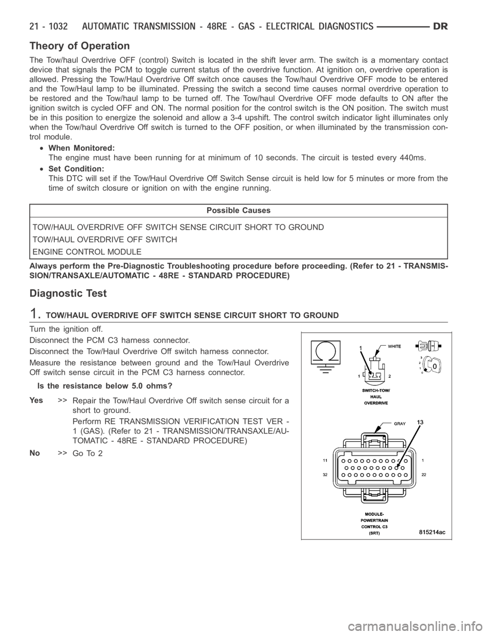
1.TOW/HAUL OVERDRIVE OFF SWITCH SENSE CIRCUIT SHORT TO GROUND
Turn the ignition off.
Disconnect the PCM C3 harness connector.
Disconnect the Tow/Haul OverdriveOff switch harness connector.
Measure the resistance between ground and the Tow/Haul Overdrive
Off switch sense circuit in the PCM C3 harness connector.
Is the resistance below 5.0 ohms?
Ye s>>
Repair the Tow/Haul Overdrive Off switch sense circuit for a
short to ground.
Perform RE TRANSMISSION VERIFICATION TEST VER -
1 (GAS). (Refer to 21 - TRANSMISSION/TRANSAXLE/AU-
TOMATIC - 48RE - STANDARD PROCEDURE)
No>>
Go To 2
Page 3554 of 5267
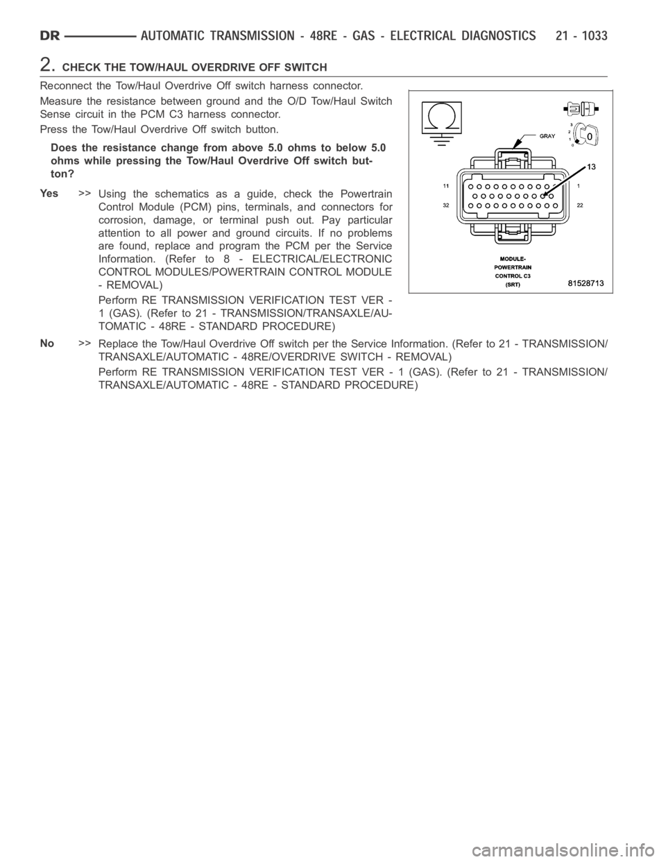
2.CHECK THE TOW/HAUL OVERDRIVE OFF SWITCH
Reconnect the Tow/Haul Overdrive Off switch harness connector.
Measure the resistance between ground and the O/D Tow/Haul Switch
Sense circuit in the PCM C3 harness connector.
Press the Tow/Haul Overdrive Off switch button.
Does the resistance change from above 5.0 ohms to below 5.0
ohms while pressing the Tow/Haul Overdrive Off switch but-
ton?
Ye s>>
Using the schematics as a guide, check the Powertrain
Control Module (PCM) pins, terminals, and connectors for
corrosion, damage, or terminal push out. Pay particular
attention to all power and ground circuits. If no problems
are found, replace and program the PCM per the Service
Information. (Refer to 8 - ELECTRICAL/ELECTRONIC
CONTROL MODULES/POWERTRAIN CONTROL MODULE
- REMOVAL)
Perform RE TRANSMISSION VERIFICATION TEST VER -
1 (GAS). (Refer to 21 - TRANSMISSION/TRANSAXLE/AU-
TOMATIC - 48RE - STANDARD PROCEDURE)
No>>
Replace the Tow/Haul Overdrive Off switch per the Service Information. (Refer to 21 - TRANSMISSION/
TRANSAXLE/AUTOMATIC - 48RE/OVERDRIVE SWITCH - REMOVAL)
Perform RE TRANSMISSION VERIFICATION TEST VER - 1 (GAS). (Refer to 21 - TRANSMISSION/
TRANSAXLE/AUTOMATIC - 48RE - STANDARD PROCEDURE)