2006 DODGE RAM SRT-10 tow
[x] Cancel search: towPage 3940 of 5267
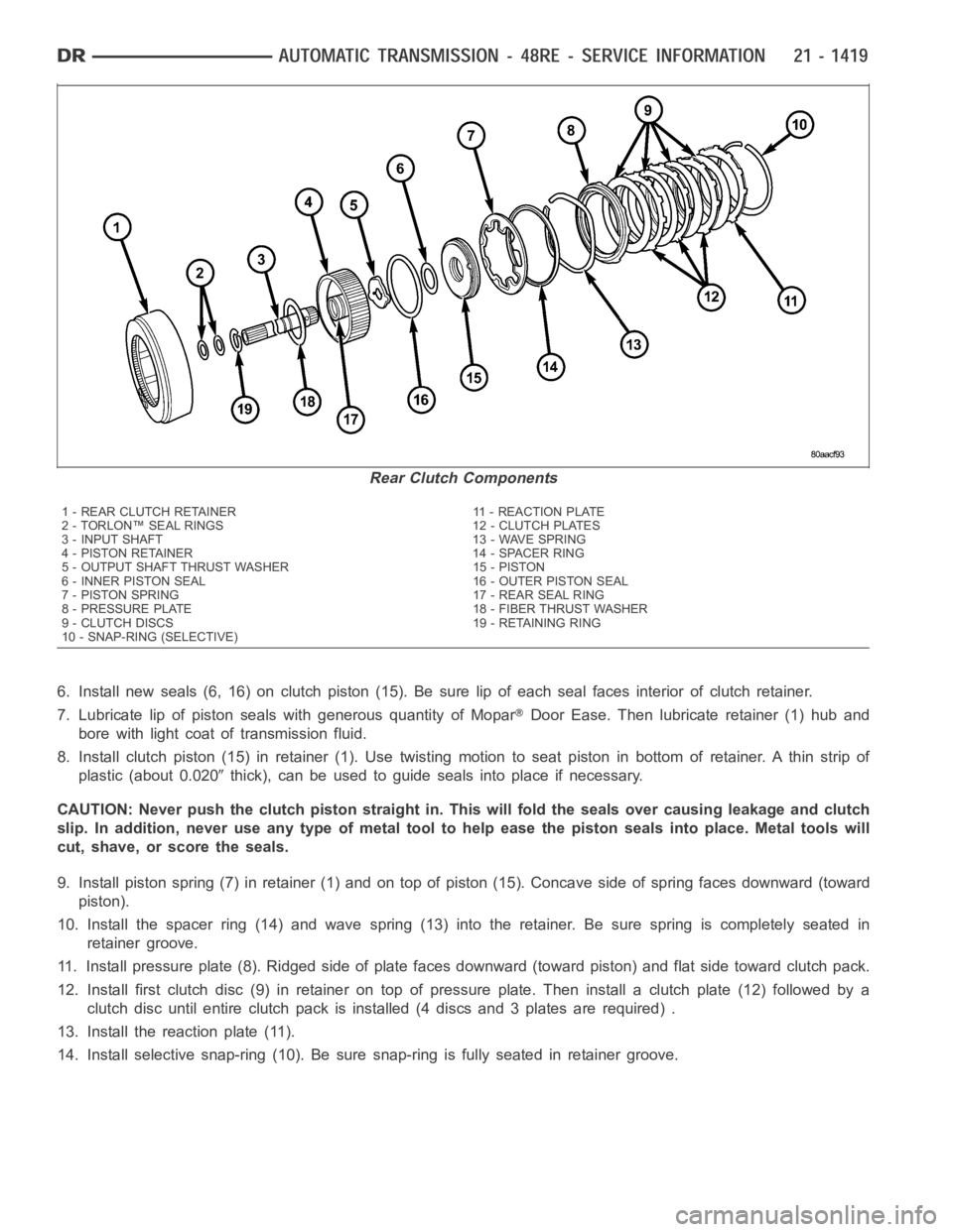
6. Install new seals (6, 16) on clutch piston (15). Be sure lip of each seal faces interior of clutch retainer.
7. Lubricate lip of piston seals with generous quantity of Mopar
Door Ease. Then lubricate retainer (1) hub and
bore with light coat of transmission fluid.
8. Install clutch piston (15) in retainer (1). Use twisting motion to seat piston in bottom of retainer. A thin strip of
plastic (about 0.020
thick), can be used to guide seals into place if necessary.
CAUTION: Never push the clutch piston straight in. This will fold the sealsover causing leakage and clutch
slip. In addition, never use any type of metal tool to help ease the piston seals into place. Metal tools will
cut, shave, or score the seals.
9. Install piston spring (7) in retainer (1) and on top of piston (15). Concave side of spring faces downward (toward
piston).
10. Install the spacer ring (14) and wave spring (13) into the retainer. Be sure spring is completely seated in
retainer groove.
11. Install pressure plate (8). Ridged side of plate faces downward (toward piston) and flat side toward clutch pack.
12. Install first clutch disc (9) in retainer on top of pressure plate. Theninstall a clutch plate (12) followed by a
clutch disc until entire clutch pack is installed (4 discs and 3 plates are required) .
13. Install the reaction plate (11).
14. Install selective snap-ring (10). Be sure snap-ring is fully seated inretainer groove.
Rear Clutch Components
1 - REAR CLUTCH RETAINER 11 - REACTION PLATE
2 - TORLON™ SEAL RINGS 12 - CLUTCH PLATES
3 - INPUT SHAFT 13 - WAVE SPRING
4 - PISTON RETAINER 14 - SPACER RING
5 - OUTPUT SHAFT THRUST WASHER 15 - PISTON
6 - INNER PISTON SEAL 16 - OUTER PISTON SEAL
7 - PISTON SPRING 17 - REAR SEAL RING
8 - PRESSURE PLATE 18 - FIBER THRUST WASHER
9 - CLUTCH DISCS 19 - RETAINING RING
10 - SNAP-RING (SELECTIVE)
Page 3956 of 5267
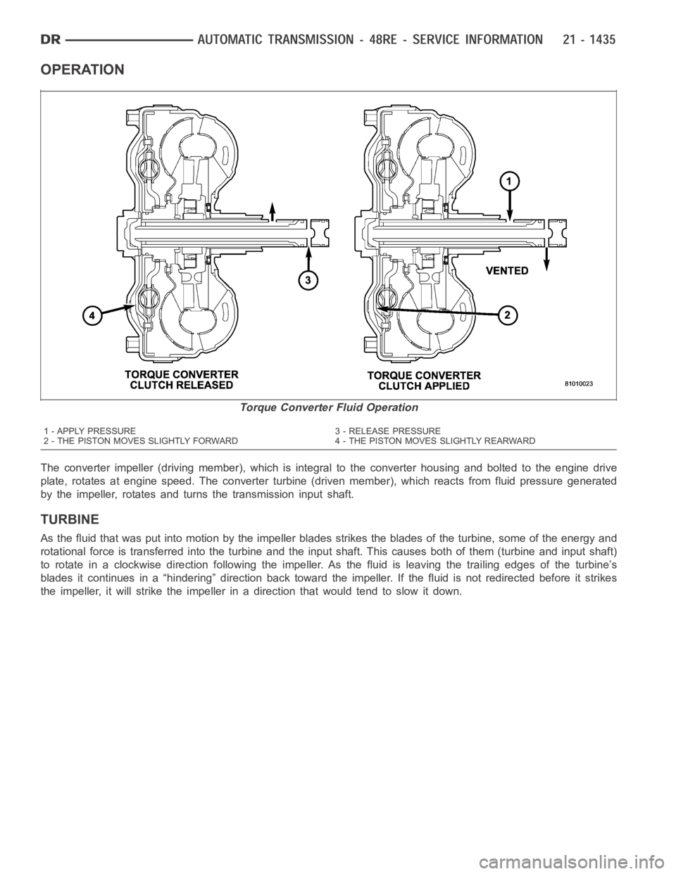
OPERATION
The converter impeller (driving member), which is integral to the converter housing and bolted to the engine drive
plate, rotates at engine speed. The converter turbine (driven member), which reacts from fluid pressure generated
by the impeller, rotates and turns the transmission input shaft.
TURBINE
As the fluid that was put into motion bythe impeller blades strikes the blades of the turbine, some of the energy and
rotational force is transferred into the turbine and the input shaft. Thiscauses both of them (turbine and input shaft)
to rotate in a clockwise direction following the impeller. As the fluid is leaving the trailing edges of the turbine’s
blades it continues in a “hindering” direction back toward the impeller. If the fluid is not redirected before it strikes
the impeller, it will strike the impeller in a direction that would tend to slow it down.
Torque Converter Fluid Operation
1 - APPLY PRESSURE 3 - RELEASE PRESSURE
2 - THE PISTON MOVES SLIGHTLY FORWARD 4 - THE PISTON MOVES SLIGHTLY REARWARD
Page 3961 of 5267
SWITCH-TOW/HAUL OVERDRIVE
DESCRIPTION
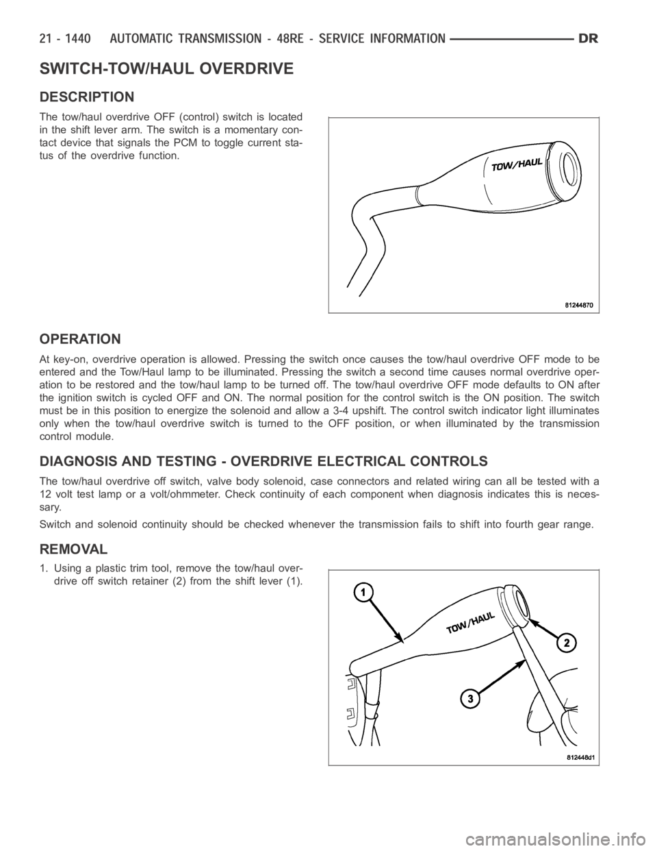
The tow/haul overdrive OFF (control) switch is located
in the shift lever arm. The switch is a momentary con-
tact device that signals the PCM to toggle current sta-
tus of the overdrive function.
OPERATION
At key-on, overdrive operation is allowed. Pressing the switch once causes the tow/haul overdrive OFF mode to be
entered and the Tow/Haul lamp to be illuminated. Pressing the switch a second time causes normal overdrive oper-
ationtoberestoredandthetow/haullamptobeturnedoff.Thetow/hauloverdrive OFF mode defaults to ON after
the ignition switch is cycled OFF and ON. The normal position for the control switch is the ON position. The switch
must be in this position to energize the solenoid and allow a 3-4 upshift. The control switch indicator light illuminates
only when the tow/haul overdrive switch is turned to the OFF position, or when illuminated by the transmission
control module.
DIAGNOSIS AND TESTING - OVERDRIVE ELECTRICAL CONTROLS
The tow/haul overdrive off switch, valve body solenoid, case connectors and related wiring can all be tested with a
12 volt test lamp or a volt/ohmmeter. Check continuity of each component when diagnosis indicates this is neces-
sary.
Switch and solenoid continuity shouldbe checked whenever the transmission fails to shift into fourth gear range.
REMOVAL
1. Using a plastic trim tool, remove the tow/haul over-
drive off switch retainer (2) from the shift lever (1).
Page 3962 of 5267
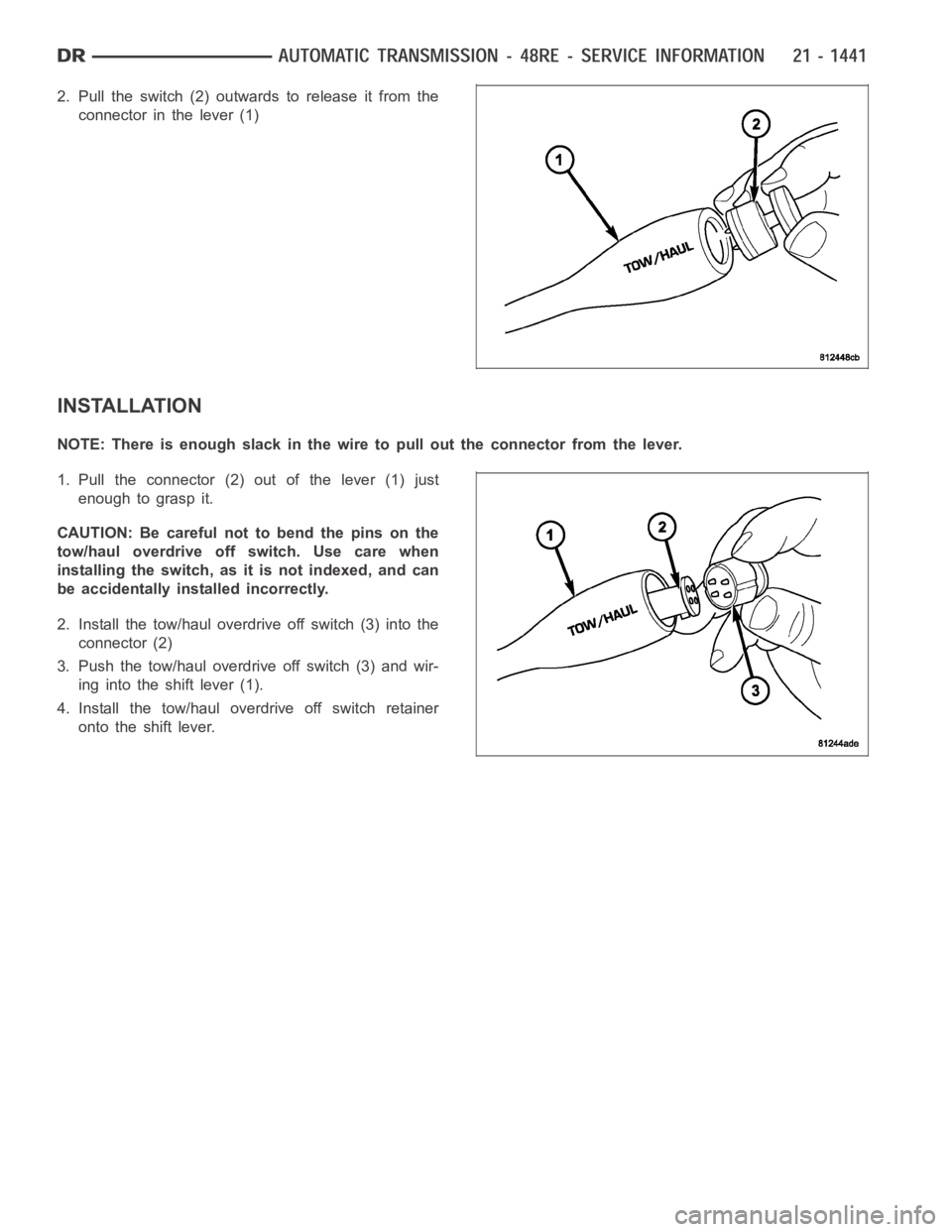
2. Pull the switch (2) outwards to release it from the
connector in the lever (1)
INSTALLATION
NOTE: There is enough slack in the wire to pull out the connector from the lever.
1. Pull the connector (2) out of the lever (1) just
enough to grasp it.
CAUTION: Be careful not to bend the pins on the
tow/haul overdrive off switch. Use care when
installing the switch, as it is not indexed, and can
be accidentally installed incorrectly.
2. Install the tow/haul overdrive off switch (3) into the
connector (2)
3. Push the tow/haul overdrive off switch (3) and wir-
ing into the shift lever (1).
4. Install the tow/haul overdrive off switch retainer
onto the shift lever.
Page 3968 of 5267
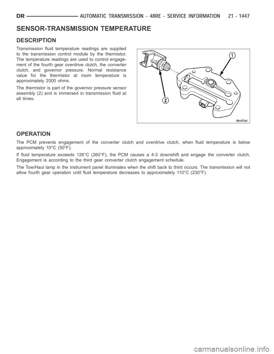
SENSOR-TRANSMISSION TEMPERATURE
DESCRIPTION
Transmission fluid temperature readings are supplied
to the transmission control module by the thermistor.
The temperature readings are used to control engage-
ment of the fourth gear overdrive clutch, the converter
clutch, and governor pressure. Normal resistance
value for the thermistor at room temperature is
approximately 2000 ohms.
The thermistor is part of the governor pressure sensor
assembly (2) and is immersed in transmission fluid at
all times.
OPERATION
The PCM prevents engagement of the converter clutch and overdrive clutch,when fluid temperature is below
approximately 10°C (50°F).
If fluid temperature exceeds 126°C (260°F), the PCM causes a 4-3 downshiftand engage the converter clutch.
Engagement is according to the third gear converter clutch engagement schedule.
The Tow/Haul lamp in the instrument panel illuminates when the shift back to third occurs. The transmission will not
allow fourth gear operation until fluid temperature decreases to approximately 110°C (230°F).
Page 3978 of 5267
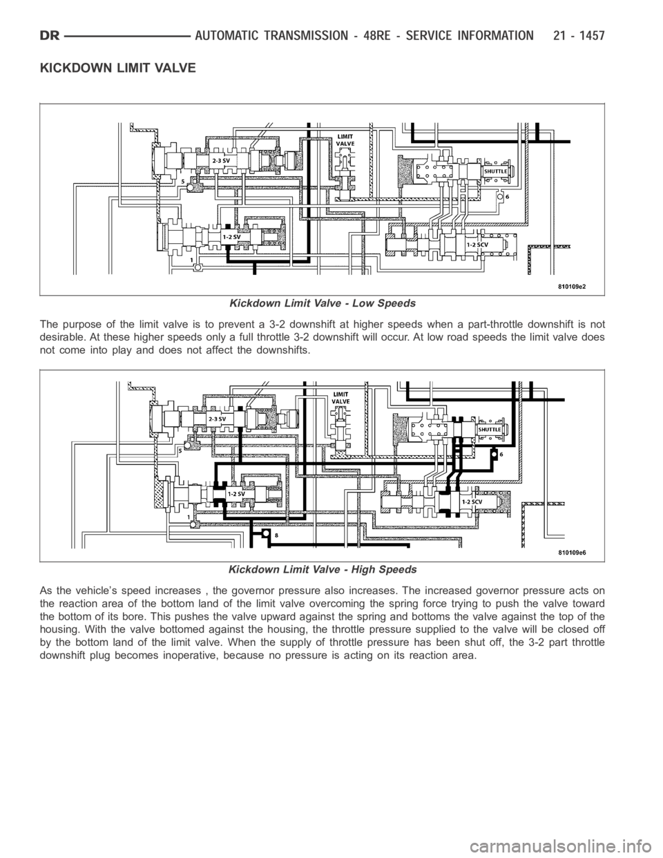
KICKDOWN LIMIT VALVE
The purpose of the limit valve is to prevent a 3-2 downshift at higher speedswhen a part-throttle downshift is not
desirable. At these higher speeds only a full throttle 3-2 downshift will occur. At low road speeds the limit valve does
not come into play and does not affect the downshifts.
As the vehicle’s speed increases , the governor pressure also increases. The increased governor pressure acts on
the reaction area of the bottom land of the limit valve overcoming the spring force trying to push the valve toward
the bottom of its bore. This pushes the valve upward against the spring and bottoms the valve against the top of the
housing. With the valve bottomed against the housing, the throttle pressure supplied to the valve will be closed off
by the bottom land of the limit valve. When the supply of throttle pressure has been shut off, the 3-2 part throttle
downshift plug becomes inoperative, because no pressure is acting on its reaction area.
Kickdown Limit Valve - Low Speeds
Kickdown Limit Valve - High Speeds
Page 3988 of 5267
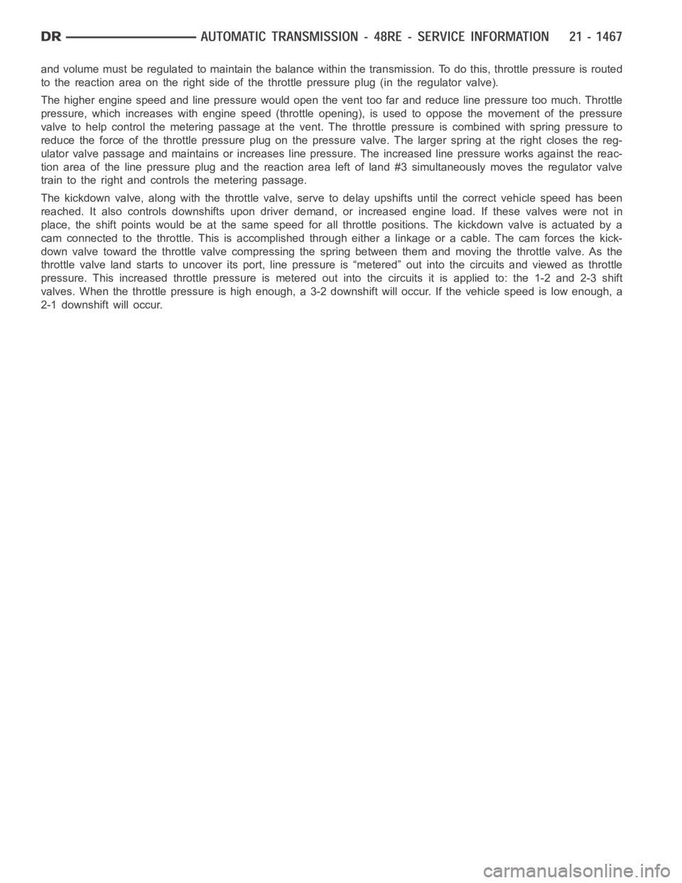
and volume must be regulated to maintain the balance within the transmission. To do this, throttle pressure is routed
tothereactionareaontherightsideofthethrottlepressureplug(intheregulator valve).
The higher engine speed and line pressure would open the vent too far and reduce line pressure too much. Throttle
pressure, which increases with engine speed (throttle opening), is used to oppose the movement of the pressure
valve to help control the metering passage at the vent. The throttle pressure is combined with spring pressure to
reduce the force of the throttle pressure plug on the pressure valve. The larger spring at the right closes the reg-
ulator valve passage and maintains or increases line pressure. The increased line pressure works against the reac-
tion area of the line pressure plug and the reaction area left of land #3 simultaneously moves the regulator valve
train to the right and controls the metering passage.
The kickdown valve, along with the throttle valve, serve to delay upshiftsuntil the correct vehicle speed has been
reached. It also controls downshifts upon driver demand, or increased engine load. If these valves were not in
place, the shift points would be at the same speed for all throttle positions. The kickdown valve is actuated by a
cam connected to the throttle. This is accomplished through either a linkage or a cable. The cam forces the kick-
down valve toward the throttle valve compressing the spring between them and moving the throttle valve. As the
throttle valve land starts to uncover its port, line pressure is “metered”out into the circuits and viewed as throttle
pressure. This increased throttle pressure is metered out into the circuits it is applied to: the 1-2 and 2-3 shift
valves. When the throttle pressure is high enough, a 3-2 downshift will occur. If the vehicle speed is low enough, a
2-1 downshift will occur.
Page 4006 of 5267

4. Remove timing valve cover.
5. Remove 3-4 timing valve and spring.
6. Remove 3-4 quick fill valve, spring and plug.
7. Remove 3-4 shift valve and spring.
8. Remove converter clutch valve, spring and plug.
9. Remove converter clutch timing valve, retainer and
valve spring.
CLEANING
Clean the valve housings, valves, plugs, springs, and separator plates with a standard parts cleaning solution only.
Do not use gasoline, kerosene, or any type of caustic solution.
Do not immerse any of the electrical components in cleaning solution. Clean the governor solenoid and sensor and
the dual solenoid and harness assembly by wiping them off with dry shop towels only.
Dry all except the electrical parts with compressed air. Make sure all passages are clean and free from obstructions.
Do not use rags or shop towels to dry or wipe off valve body components. Lint from these materials can
stick to valve body parts, interfere with valve operation, and clog filters and fluid passages.
Wipe the governor pressure sensor and solenoid valve with dry, lint free shop towels only. The O-rings on the sen-
sor and solenoid valve are the only serviceable components. Be sure the vent ports in the solenoid valve are open
and not blocked by dirt or debris. Replace the valve and/or sensor only whenDRB scan tool diagnosis indicates this
is necessary. Or, if either part has sustained physical damage (dented, deformed, broken, etc.).
CAUTION: Do not turn the small screw at the end of the solenoid valve for any reason. Turning the screw
in either direction will ruin solenoid calibration and result in solenoidfailure. In addition, the filter on the
solenoid valve is NOT serviceable. Do not try to remove the filter as this will damage the valve housing.
INSPECTION
Inspect the throttle and manual valve levers and shafts. Do not attempt to straighten a bent shaft or correct a loose
lever. Replace these components if worn, bent, loose or damaged in any way.
Inspect all of the valve body mating surfaces for scratches, nicks, burrs,or distortion. Use a straightedge to check
surface flatness. Minor scratches may be removed with crocus cloth using only very light pressure.
Minor distortion of a valve body mating surface may be corrected by smoothing the surface with a sheet of crocus
cloth. Position the crocus cloth on a surface plate, sheet of plate glass orequally flat surface. If distortion is severe
or any surfaces are heavily scored, the valve body will have to be replaced.
CAUTION: Many of the valves and plugs, such as the throttle valve, shuttle valve plug, 1-2 shift valve and
1-2 governor plug, are made of coated aluminum. Aluminum components are identified by the dark color of
thespecialcoatingappliedtothesurface(orbytestingwithamagnet).Donot sand aluminum valves or
plugs under any circumstances. This practice could damage the special coating causing the valves/plugs to
stick and bind.
Inspect the valves and plugs for scratches, burrs, nicks, or scores. Minorsurface scratches on steel valves and
plugs can be removed with crocus cloth butdo not round off the edges of the valve or plug lands.Maintaining