2006 DODGE RAM SRT-10 air condition
[x] Cancel search: air conditionPage 4086 of 5267
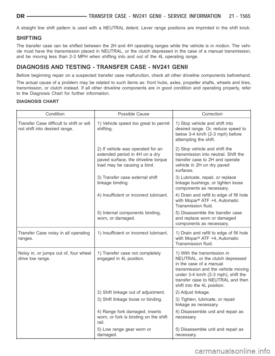
A straight line shift pattern is used with a NEUTRAL detent. Lever range positions are imprinted in the shift knob.
SHIFTING
The transfer case can be shifted between the 2H and 4H operating ranges while the vehicle is in motion. The vehi-
cle must have the transmission placed in NEUTRAL, or the clutch depressed in the case of a manual transmission,
and be moving less than 2-3 MPH when shifting into and out of the 4L operatingrange.
DIAGNOSIS AND TESTING - TRANSFER CASE - NV241 GENII
Before beginning repair on a suspected transfer case malfunction, check all other driveline components beforehand.
The actual cause of a problem may be related to such items as: front hubs, axles, propeller shafts, wheels and tires,
transmission, or clutch instead. If all other driveline components are ingood condition and operating properly, refer
to the Diagnosis Chart for further information.
DIAGNOSIS CHART
Condition Possible Cause Correction
Transfer Case difficult to shift or will
not shift into desired range.1) Vehicle speed too great to permit
shifting.1) Stop vehicle and shift into
desired range. Or, reduce speed to
below 3-4 km/h (2-3 mph) before
attempting the shift.
2) If vehicle was operated for an
extended period in 4H on a dry
paved surface, the driveline torque
load may be causing a bind.2) Stop vehicle and shift the
transmission into neutral. Shift the
transfer case to 2H and operate
vehicle in 2H on dry paved
surfaces.
3) Transfer case external shift
linkage binding.3) Lubricate, repair, or replace
linkage bushings, or tighten loose
components as necessary.
4) Insufficient or incorrect lubricant. 4) Drain and refill to edge of fillhole
with Mopar
ATF +4, Automatic
Transmission fluid.
5) Internal components binding,
worn, or damaged.5) Disassemble the transfer case
and replace worn or damaged
components as necessary.
Transfer Case noisy in all operating
ranges.1) Insufficient or incorrect lubricant. 1) Drain and refill to edge of fillhole
with Mopar
ATF +4, Automatic
Transmission fluid.
Noisy in, or jumps out of, four wheel
drive low range.1) Transfer case not completely
engaged in 4L position.1) With the transmission in
NEUTRAL, or the clutch depressed
in the case of a manual
transmission and the vehicle moving
under 3-4 km/h (2-3 mph), shift the
transfer case to NEUTRAL and then
shift into the 4L position.
2) Shift linkage out of adjustment. 2) Adjust linkage.
3) Shift linkage loose or binding. 3) Tighten, lubricate, or repair
linkage as necessary.
4) Range fork damaged, inserts
worn, or fork is binding on the shift
rail.4) Disassemble unit and repair as
necessary.
5) Low range gear worn or
damaged.5) Disassemble unit and repair as
necessary.
Page 4102 of 5267
LOW RANGE ANNULUS GEAR
Inspect annulus gear (2) condition carefully. The gear
is only serviced as part of the front case. If the gear is
damaged, it will be necessary to replace the gear and
front case as an assembly. Do not attempt to remove
the gear.
FRONT CASE AND REAR CASE
Inspect the cases for wear and damage.
Check case condition. If leaks were a problem, look for gouges and severe scoring of case sealing surfaces. Also
make sure the front case mounting studs are in good condition.
Check the front case mounting studs and vent tube. The tube can be secured with Loctite™ 271 or 680 if loose.
Thestudthreadscanbecleanedupwithadieifnecessary.Alsocheckcondition of the fill/drain plug threads in the
rear case. The threads can be repaired with a thread chaser or tap if necessary. Or the threads can be repaired with
Helicoil™ stainless steel inserts if required.
OIL PUMP/OIL PICKUP
Examine the oil pump pickup parts. Replace the pump if any part appears to beworn or damaged. Do not disas-
semble the pump as individual parts are not available. The pump is only available as a complete assembly. The
pickup screen, hose, and tube are the only serviceable parts and are available separately.
ASSEMBLY
BEARINGS AND SEALS
1. Remove the input shaft bearing (1) from the front
case (2) with suitable snap-ring pliers.
2. Transfer the retaining ring to the new bearing if
necessary and install the bearing into the front
case.
Page 4128 of 5267
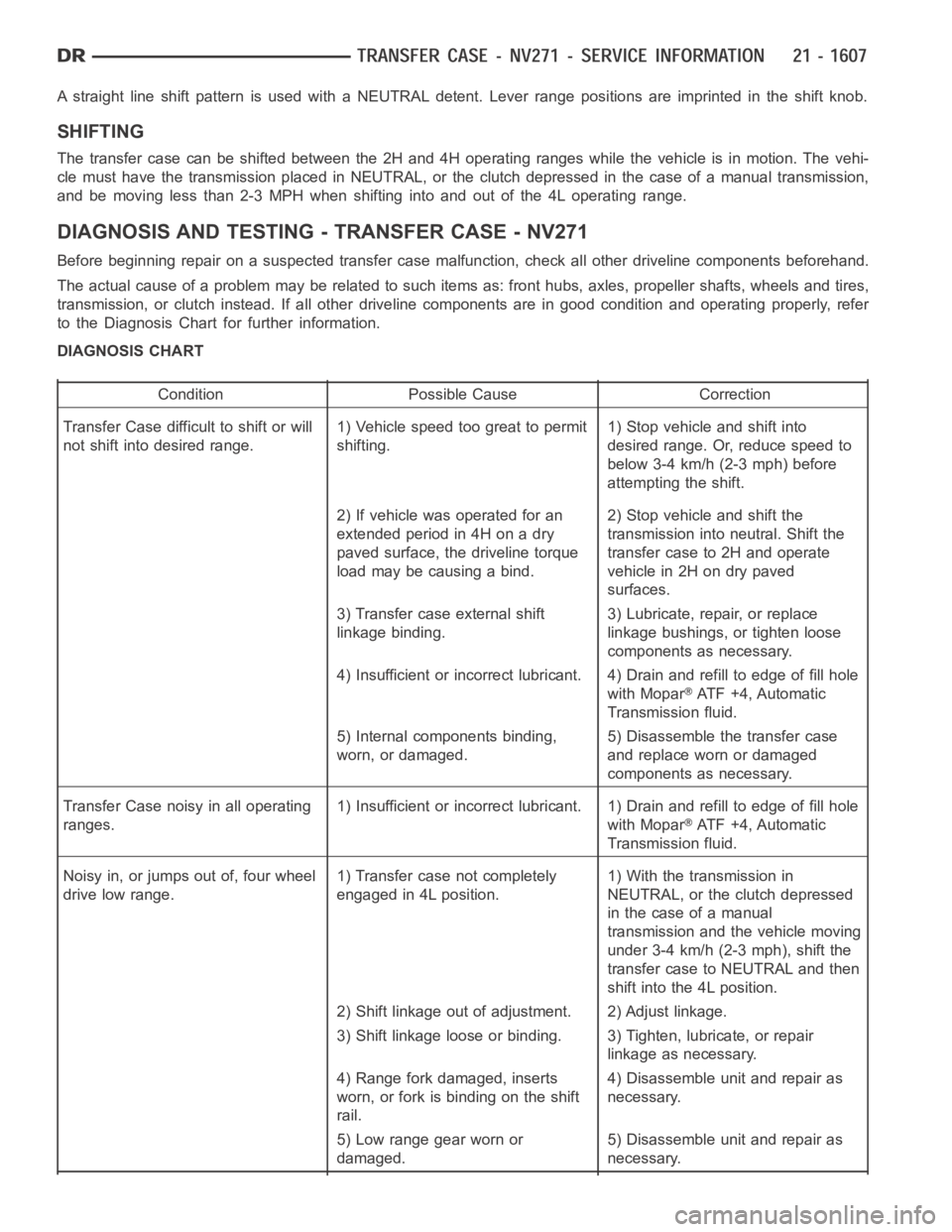
A straight line shift pattern is used with a NEUTRAL detent. Lever range positions are imprinted in the shift knob.
SHIFTING
The transfer case can be shifted between the 2H and 4H operating ranges while the vehicle is in motion. The vehi-
cle must have the transmission placed in NEUTRAL, or the clutch depressed in the case of a manual transmission,
and be moving less than 2-3 MPH when shifting into and out of the 4L operatingrange.
DIAGNOSIS AND TESTING - TRANSFER CASE - NV271
Before beginning repair on a suspected transfer case malfunction, check all other driveline components beforehand.
The actual cause of a problem may be related to such items as: front hubs, axles, propeller shafts, wheels and tires,
transmission, or clutch instead. If all other driveline components are ingood condition and operating properly, refer
to the Diagnosis Chart for further information.
DIAGNOSIS CHART
Condition Possible Cause Correction
Transfer Case difficult to shift or will
not shift into desired range.1) Vehicle speed too great to permit
shifting.1) Stop vehicle and shift into
desired range. Or, reduce speed to
below 3-4 km/h (2-3 mph) before
attempting the shift.
2) If vehicle was operated for an
extended period in 4H on a dry
paved surface, the driveline torque
load may be causing a bind.2) Stop vehicle and shift the
transmission into neutral. Shift the
transfer case to 2H and operate
vehicle in 2H on dry paved
surfaces.
3) Transfer case external shift
linkage binding.3) Lubricate, repair, or replace
linkage bushings, or tighten loose
components as necessary.
4) Insufficient or incorrect lubricant. 4) Drain and refill to edge of fillhole
with Mopar
ATF +4, Automatic
Transmission fluid.
5) Internal components binding,
worn, or damaged.5) Disassemble the transfer case
and replace worn or damaged
components as necessary.
Transfer Case noisy in all operating
ranges.1) Insufficient or incorrect lubricant. 1) Drain and refill to edge of fillhole
with Mopar
ATF +4, Automatic
Transmission fluid.
Noisy in, or jumps out of, four wheel
drive low range.1) Transfer case not completely
engaged in 4L position.1) With the transmission in
NEUTRAL, or the clutch depressed
in the case of a manual
transmission and the vehicle moving
under 3-4 km/h (2-3 mph), shift the
transfer case to NEUTRAL and then
shift into the 4L position.
2) Shift linkage out of adjustment. 2) Adjust linkage.
3) Shift linkage loose or binding. 3) Tighten, lubricate, or repair
linkage as necessary.
4) Range fork damaged, inserts
worn, or fork is binding on the shift
rail.4) Disassemble unit and repair as
necessary.
5) Low range gear worn or
damaged.5) Disassemble unit and repair as
necessary.
Page 4147 of 5267
FRONT CASE AND REAR CASE
Inspect the cases for wear and damage.
Check case condition. If leaks were a problem, look for gouges and severe scoring of case sealing surfaces. Also
make sure the front case mounting studs are in good condition.
Check the front case mounting studs and vent tube. The tube can be secured with Loctite™ 271 or 680 if loose.
Thestudthreadscanbecleanedupwithadieifnecessary.Alsocheckcondition of the fill/drain plug threads in the
rear case. The threads can be repaired with a thread chaser or tap if necessary. Or the threads can be repaired with
Helicoil™ stainless steel inserts if required.
OIL PUMP/OIL PICKUP
Examine the oil pump pickup parts. Replace the pump if any part appears to beworn or damaged. Do not disas-
semble the pump as individual parts are not available. The pump is only available as a complete assembly. The
pickup screen, hose, and tube are the only serviceable parts and are available separately.
ASSEMBLY
BEARINGS AND SEALS
1. Remove the input shaft bearing snap-ring from the
front case half with suitable snap-ring pliers.
2. Remove the input shaft bearing from the front case
half with Bearing Installer 6953 (3) and Universal
Handle C-4171 (2).
3. Install the input shaft bearing into the front case
half with Bearing Cup Installer 8151 (3) inverted on
Universal Handle C-4171 (2).
4. Install the input shaft bearing snap-ring into the
front case half with suitable snap-ring pliers.
Page 4179 of 5267
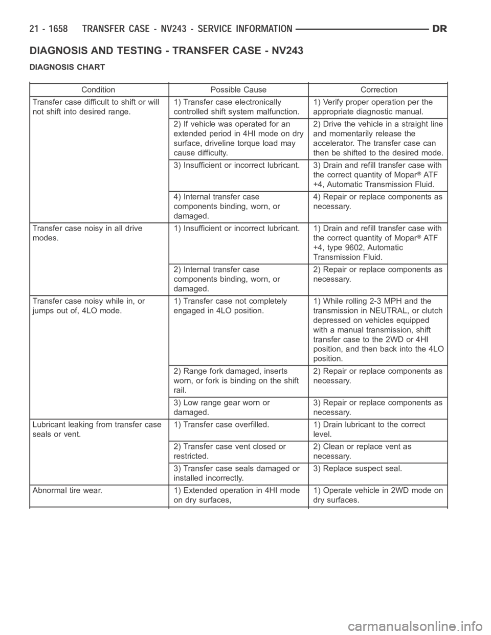
DIAGNOSIS AND TESTING - TRANSFER CASE - NV243
DIAGNOSIS CHART
Condition Possible Cause Correction
Transfer case difficult to shift or will
not shift into desired range.1) Transfer case electronically
controlled shift system malfunction.1) Verify proper operation per the
appropriate diagnostic manual.
2) If vehicle was operated for an
extended period in 4HI mode on dry
surface, driveline torque load may
cause difficulty.2) Drive the vehicle in a straight line
and momentarily release the
accelerator. The transfer case can
then be shifted to the desired mode.
3) Insufficient or incorrect lubricant. 3) Drain and refill transfer casewith
the correct quantity of Mopar
AT F
+4, Automatic Transmission Fluid.
4) Internal transfer case
components binding, worn, or
damaged.4) Repair or replace components as
necessary.
Transfer case noisy in all drive
modes.1) Insufficient or incorrect lubricant. 1) Drain and refill transfer casewith
the correct quantity of Mopar
AT F
+4, type 9602, Automatic
Transmission Fluid.
2) Internal transfer case
components binding, worn, or
damaged.2) Repair or replace components as
necessary.
Transfer case noisy while in, or
jumps out of, 4LO mode.1) Transfer case not completely
engaged in 4LO position.1) While rolling 2-3 MPH and the
transmission in NEUTRAL, or clutch
depressed on vehicles equipped
with a manual transmission, shift
transfer case to the 2WD or 4HI
position, and then back into the 4LO
position.
2) Range fork damaged, inserts
worn, or fork is binding on the shift
rail.2) Repair or replace components as
necessary.
3) Low range gear worn or
damaged.3) Repair or replace components as
necessary.
Lubricant leaking from transfer case
seals or vent.1) Transfer case overfilled. 1) Drain lubricant to the correct
level.
2) Transfer case vent closed or
restricted.2) Clean or replace vent as
necessary.
3) Transfer case seals damaged or
installed incorrectly.3) Replace suspect seal.
Abnormal tire wear. 1) Extended operation in 4HI mode
on dry surfaces,1) Operate vehicle in 2WD mode on
dry surfaces.
Page 4194 of 5267
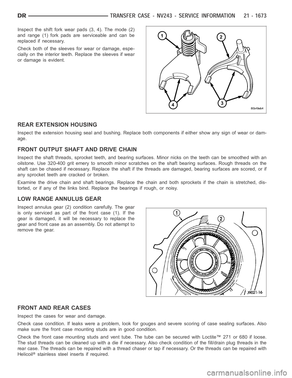
Inspect the shift fork wear pads (3, 4). The mode (2)
and range (1) fork pads are serviceable and can be
replaced if necessary.
Check both of the sleeves for wear or damage, espe-
cially on the interior teeth. Replace the sleeves if wear
or damage is evident.
REAR EXTENSION HOUSING
Inspect the extension housing seal and bushing. Replace both components if either show any sign of wear or dam-
age.
FRONT OUTPUT SHAFT AND DRIVE CHAIN
Inspect the shaft threads, sprocket teeth, and bearing surfaces. Minor nicksontheteethcanbesmoothedwithan
oilstone. Use 320-400 grit emery to smooth minor scratches on the shaft bearing surfaces. Rough threads on the
shaft can be chased if necessary. Replace the shaft if the threads are damaged, bearing surfaces are scored, or if
any sprocket teeth are cracked or broken.
Examine the drive chain and shaft bearings. Replace the chain and both sprockets if the chain is stretched, dis-
torted, or if any of the links bind. Replace the bearings if rough, or noisy.
LOW RANGE ANNULUS GEAR
Inspect annulus gear (2) condition carefully. The gear
is only serviced as part of the front case (1). If the
gear is damaged, it will be necessary to replace the
gear and front case as an assembly. Do not attempt to
remove the gear.
FRONT AND REAR CASES
Inspect the cases for wear and damage.
Check case condition. If leaks were a problem, look for gouges and severe scoring of case sealing surfaces. Also
make sure the front case mounting studs are in good condition.
Check the front case mounting studs and vent tube. The tube can be secured with Loctite™ 271 or 680 if loose.
Thestudthreadscanbecleanedupwithadieifnecessary.Alsocheckcondition of the fill/drain plug threads in the
rear case. The threads can be repaired with a thread chaser or tap if necessary. Or the threads can be repaired with
Helicoil
stainless steel inserts if required.
Page 4223 of 5267
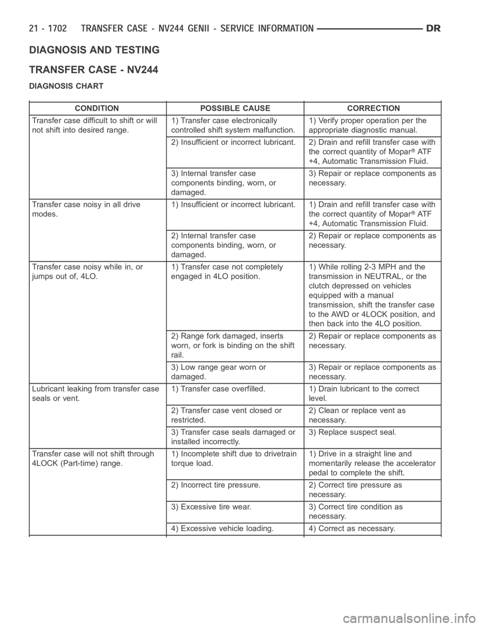
DIAGNOSIS AND TESTING
TRANSFER CASE - NV244
DIAGNOSIS CHART
CONDITION POSSIBLE CAUSE CORRECTION
Transfer case difficult to shift or will
not shift into desired range.1) Transfer case electronically
controlled shift system malfunction.1) Verify proper operation per the
appropriate diagnostic manual.
2) Insufficient or incorrect lubricant. 2) Drain and refill transfer casewith
the correct quantity of Mopar
AT F
+4, Automatic Transmission Fluid.
3) Internal transfer case
components binding, worn, or
damaged.3) Repair or replace components as
necessary.
Transfer case noisy in all drive
modes.1) Insufficient or incorrect lubricant. 1) Drain and refill transfer casewith
the correct quantity of Mopar
AT F
+4, Automatic Transmission Fluid.
2) Internal transfer case
components binding, worn, or
damaged.2) Repair or replace components as
necessary.
Transfer case noisy while in, or
jumps out of, 4LO.1) Transfer case not completely
engaged in 4LO position.1) While rolling 2-3 MPH and the
transmission in NEUTRAL, or the
clutch depressed on vehicles
equipped with a manual
transmission, shift the transfer case
to the AWD or 4LOCK position, and
then back into the 4LO position.
2) Range fork damaged, inserts
worn, or fork is binding on the shift
rail.2) Repair or replace components as
necessary.
3) Low range gear worn or
damaged.3) Repair or replace components as
necessary.
Lubricant leaking from transfer case
seals or vent.1) Transfer case overfilled. 1) Drain lubricant to the correct
level.
2) Transfer case vent closed or
restricted.2) Clean or replace vent as
necessary.
3) Transfer case seals damaged or
installed incorrectly.3) Replace suspect seal.
Transfer case will not shift through
4LOCK (Part-time) range.1) Incomplete shift due to drivetrain
torque load.1)Driveinastraightlineand
momentarily release the accelerator
pedal to complete the shift.
2) Incorrect tire pressure. 2) Correct tire pressure as
necessary.
3) Excessive tire wear. 3) Correct tire condition as
necessary.
4) Excessive vehicle loading. 4) Correct as necessary.
Page 4238 of 5267
REAR EXTENSION HOUSING
Inspect the extension housing seal and bushing. Replace both components if either show any sign of wear or dam-
age.
FRONT OUTPUT SHAFT AND DRIVE CHAIN
Inspect the shaft splines and bearing surfaces. Minor nicks on the splinescanbesmoothedwithanoilstone.Use
320-400 grit emery to smooth minor scratches on the shaft bearing surfaces. Replace the shaft if the bearing sur-
faces are scored or if any of the splines are cracked or broken.
Examine the drive chain and shaft bearings. Replace the chain and both sprockets if the chain is stretched, dis-
torted, or if any of the links bind. Replace the bearings if rough, or noisy.
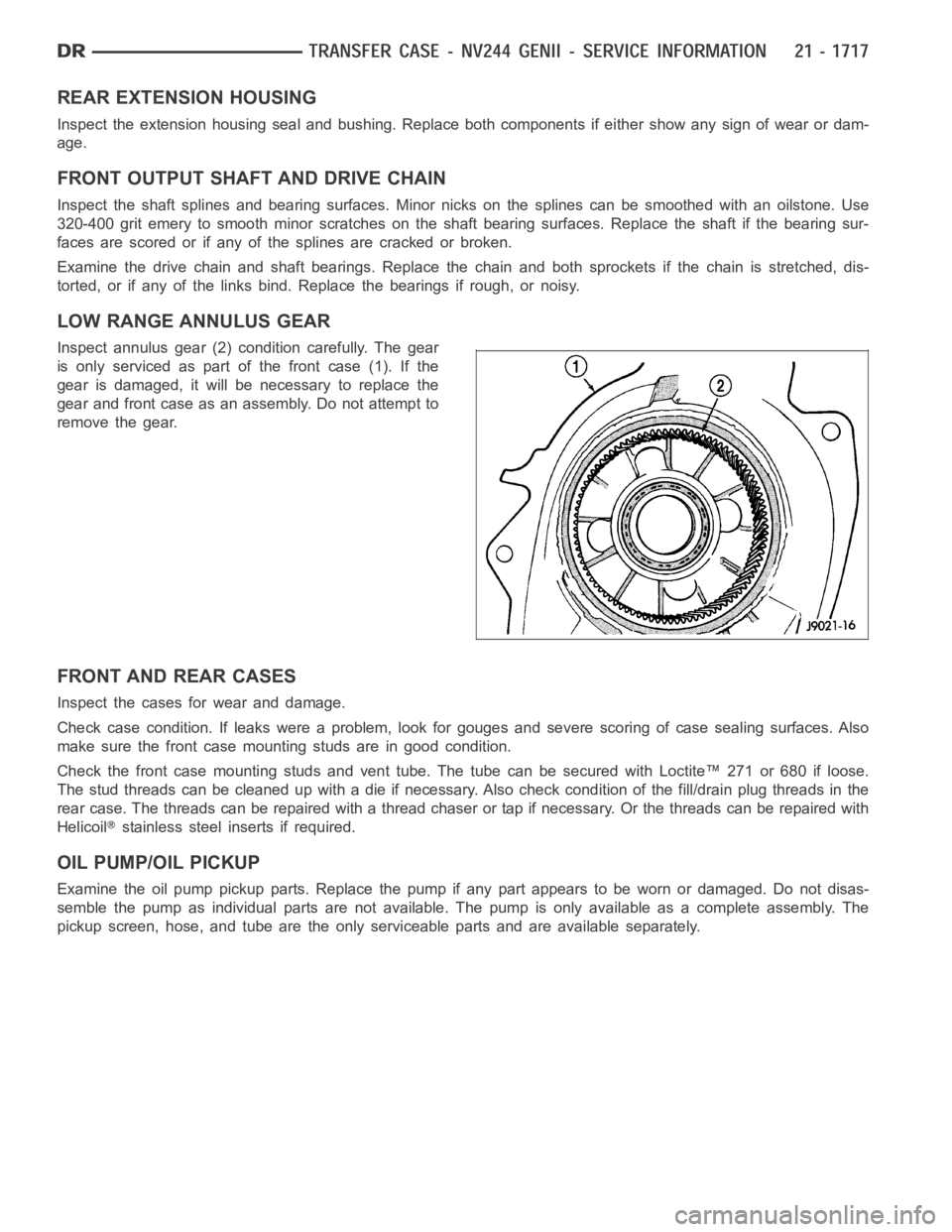
LOW RANGE ANNULUS GEAR
Inspect annulus gear (2) condition carefully. The gear
is only serviced as part of the front case (1). If the
gear is damaged, it will be necessary to replace the
gear and front case as an assembly. Do not attempt to
remove the gear.
FRONT AND REAR CASES
Inspect the cases for wear and damage.
Check case condition. If leaks were a problem, look for gouges and severe scoring of case sealing surfaces. Also
make sure the front case mounting studs are in good condition.
Check the front case mounting studs and vent tube. The tube can be secured with Loctite™ 271 or 680 if loose.
Thestudthreadscanbecleanedupwithadieifnecessary.Alsocheckcondition of the fill/drain plug threads in the
rear case. The threads can be repaired with a thread chaser or tap if necessary. Or the threads can be repaired with
Helicoil
stainless steel inserts if required.
OIL PUMP/OIL PICKUP
Examine the oil pump pickup parts. Replace the pump if any part appears to beworn or damaged. Do not disas-
semble the pump as individual parts are not available. The pump is only available as a complete assembly. The
pickup screen, hose, and tube are the only serviceable parts and are available separately.