2006 DODGE RAM SRT-10 air condition
[x] Cancel search: air conditionPage 4266 of 5267
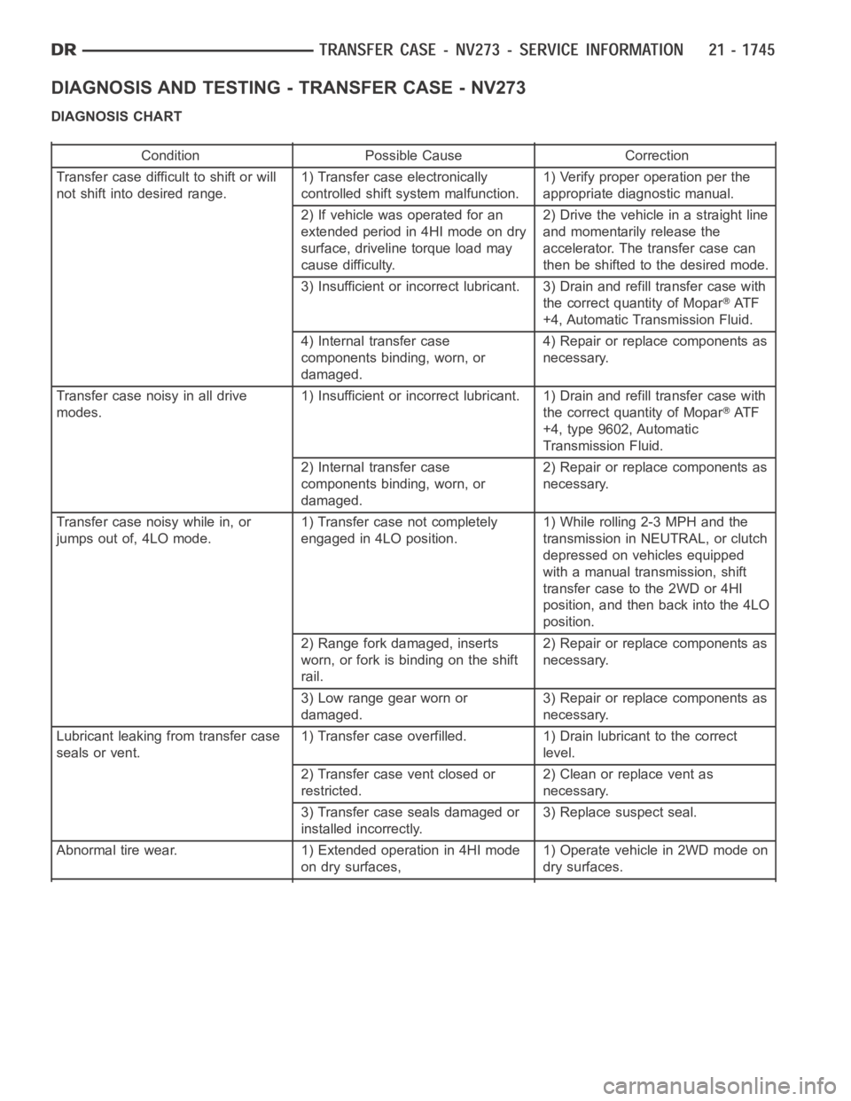
DIAGNOSIS AND TESTING - TRANSFER CASE - NV273
DIAGNOSIS CHART
Condition Possible Cause Correction
Transfer case difficult to shift or will
not shift into desired range.1) Transfer case electronically
controlled shift system malfunction.1) Verify proper operation per the
appropriate diagnostic manual.
2) If vehicle was operated for an
extended period in 4HI mode on dry
surface, driveline torque load may
cause difficulty.2) Drive the vehicle in a straight line
and momentarily release the
accelerator. The transfer case can
then be shifted to the desired mode.
3) Insufficient or incorrect lubricant. 3) Drain and refill transfer casewith
the correct quantity of Mopar
AT F
+4, Automatic Transmission Fluid.
4) Internal transfer case
components binding, worn, or
damaged.4) Repair or replace components as
necessary.
Transfer case noisy in all drive
modes.1) Insufficient or incorrect lubricant. 1) Drain and refill transfer casewith
the correct quantity of Mopar
AT F
+4, type 9602, Automatic
Transmission Fluid.
2) Internal transfer case
components binding, worn, or
damaged.2) Repair or replace components as
necessary.
Transfer case noisy while in, or
jumps out of, 4LO mode.1) Transfer case not completely
engaged in 4LO position.1) While rolling 2-3 MPH and the
transmission in NEUTRAL, or clutch
depressed on vehicles equipped
with a manual transmission, shift
transfer case to the 2WD or 4HI
position, and then back into the 4LO
position.
2) Range fork damaged, inserts
worn, or fork is binding on the shift
rail.2) Repair or replace components as
necessary.
3) Low range gear worn or
damaged.3) Repair or replace components as
necessary.
Lubricant leaking from transfer case
seals or vent.1) Transfer case overfilled. 1) Drain lubricant to the correct
level.
2) Transfer case vent closed or
restricted.2) Clean or replace vent as
necessary.
3) Transfer case seals damaged or
installed incorrectly.3) Replace suspect seal.
Abnormal tire wear. 1) Extended operation in 4HI mode
on dry surfaces,1) Operate vehicle in 2WD mode on
dry surfaces.
Page 4284 of 5267
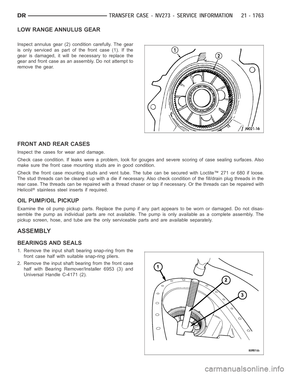
LOW RANGE ANNULUS GEAR
Inspect annulus gear (2) condition carefully. The gear
is only serviced as part of the front case (1). If the
gear is damaged, it will be necessary to replace the
gear and front case as an assembly. Do not attempt to
remove the gear.
FRONT AND REAR CASES
Inspect the cases for wear and damage.
Check case condition. If leaks were a problem, look for gouges and severe scoring of case sealing surfaces. Also
make sure the front case mounting studs are in good condition.
Check the front case mounting studs and vent tube. The tube can be secured with Loctite™ 271 or 680 if loose.
Thestudthreadscanbecleanedupwithadieifnecessary.Alsocheckcondition of the fill/drain plug threads in the
rear case. The threads can be repaired with a thread chaser or tap if necessary. Or the threads can be repaired with
Helicoil
stainless steel inserts if required.
OIL PUMP/OIL PICKUP
Examine the oil pump pickup parts. Replace the pump if any part appears to beworn or damaged. Do not disas-
semble the pump as individual parts are not available. The pump is only available as a complete assembly. The
pickup screen, hose, and tube are the only serviceable parts and are available separately.
ASSEMBLY
BEARINGS AND SEALS
1. Remove the input shaft bearing snap-ring from the
front case half with suitable snap-ring pliers.
2. Remove the input shaft bearing from the front case
half with Bearing Remover/Installer 6953 (3) and
Universal Handle C-4171 (2).
Page 4339 of 5267
BODY
WARNING
SAFETY PRECAUTIONS AND WARNINGS
WARNING: Use an OSHA approved breathing filter when spraying paint or solvents in a confined area. Per-
sonal injury can result.
Avoidprolongedskincontactwithpetroleumoralcohol–basedcleaningsolvents. Personal injury can
result.
Do not stand under a hoisted vehicle that is not properly supported on safety stands. Personal injury can
result.
CAUTION: When holes must be drilled or punched in an inner body panel, verify depth of space to the outer
body panel, electrical wiring, or other components. Damage to vehicle canresult.
Do not weld exterior panels unless combustible material on the interior ofvehicle is removed from the
repair area. Fire or hazardous conditions, can result.
Always have a fire extinguisher ready for use when welding.
Disconnect the negative (-) cable clamp from the battery when servicing electrical components that are
live when the ignition is OFF. Damage to electrical system can result.
Do not use abrasive chemicals or compounds on painted surfaces. Damage to finish can result.
Do not use harsh alkaline based cleaning solvents on painted or upholstered surfaces. Damage to finish
or color can result.
Do not hammer or pound on plastic trim panel when servicing interior trim. Plastic panels can break.
DIAGNOSIS AND TESTING
WAT E R L E A K S
Water leaks can be caused by poor sealing, improper body component alignment, body seam porosity, missing
plugs, or blocked drain holes. Centrifugal and gravitational force can cause water to drip from a location away from
the actual leak point, making leak detection difficult. All body sealing points should be water tight in normal wet-
driving conditions. Water flowing downward from the front of the vehicle should not enter the passenger or luggage
compartment. Moving sealing surfaces will not always seal water tight under all conditions. At times, side glass or
door seals will allow water to enter the passenger compartment during highpressure washing or hard driving rain
(severe) conditions. Overcompensating on door or glass adjustments to stop a water leak that occurs under severe
conditions can cause premature sealwear and excessive closing or latching effort. After completing a repair, water
test vehicle to verify leak has stopped before returning vehicle to use.
VISUAL INSPECTION BEFORE WATER LEAK TESTS
Verify that floor and body plugs are in place, body drains are clear, and body components are properly aligned and
sealed. If component alignment or sealing is necessary, refer to the appropriate section of this group for proper
procedures.
WATER LEAK TESTS
WARNING: Do not use electric shop lights or tools in water test area. Personal injury can result.
When the conditions causing a water leak have been determined, simulate the conditions as closely as possible.
Ifaleakoccurswiththevehicleparkedinasteadylightrain,floodtheleak area with an open-ended garden
hose.
If a leak occurs while driving at highway speeds in a steady rain, test the leak area with a reasonable velocity
stream or fan spray of water. Direct the spray in a direction comparable to actual conditions.
If a leak occurs when the vehicle is parked on an incline, hoist the end or sideofthevehicletosimulatethis
condition. This method can be used when the leak occurs when the vehicle accelerates, stops or turns. If the
leak occurs on acceleration, hoist the front of the vehicle. If the leak occurs when braking, hoist the back of the
Page 4340 of 5267
vehicle. If the leak occurs on left turns, hoist the left side of the vehicle. If the leak occurs on right turns, hoist
the right side of the vehicle. For hoisting recommendations (Refer to LUBRICATION & MAINTENANCE/HOIST-
ING - STANDARD PROCEDURE).
WATER LEAK DETECTION
To detect a water leak point-of-entry, do a water test and watch for water tracks or droplets forming on the inside of
the vehicle. If necessary, remove interior trim covers or panels to gain visual access to the leak area. If the hose
cannot be positioned without being held, have someone help do the water test.
Some water leaks must be tested for a considerable length of time to become apparent. When a leak appears, find
the highest point of the water track or drop. The highest point usually willshow the point of entry. After leak point
has been found, repair the leak and water test to verify that the leak has stopped.
Locating the entry point of water that is leaking into a cavity between panels can be difficult. The trapped water may
splash or run from the cavity, often at adistance from the entry point. Mostwater leaks of this type become appar-
ent after accelerating, stopping, turning, or when on an incline.
MIRROR INSPECTION METHOD
When a leak point area is visually obstructed, use a suitable mirror to gainvisual access. A mirror can also be used
to deflect light to a limited-access area to assist in locating a leak point.
BRIGHT LIGHT LEAK TEST METHOD
Some water leaks in the luggage compartment can be detected without water testing. Position the vehicle in a
brightly lit area. From inside the darkened luggage compartment inspect around seals and body seams. If neces-
sary, have a helper direct a drop light over the suspected leak areas aroundthe luggage compartment. If light is
visible through a normally sealed location, water could enter through theopening.
PRESSURIZED LEAK TEST METHOD
When a water leak into the passenger compartment cannot be detected by water testing, pressurize the passenger
compartment and soap test exterior ofthe vehicle. To pressurize the passenger compartment, close all doors and
windows, start engine, and set heater control to high blower in HEAT position. If engine can not be started, connect
a charger to the battery to ensure adequate voltage to the blower. With interior pressurized, apply dish detergent
solution to suspected leak area on the exterior of the vehicle. Apply detergent solution with spray device or soft
bristle brush. If soap bubbles occur at a body seam, joint, seal or gasket, the leak entry point could be at that
location.
WIND NOISE
Wind noise is the result of most air leaks. Air leaks can be caused by poor sealing, improper body component
alignment, body seam porosity, or missing plugs in the engine compartmentor door hinge pillar areas. All body
sealing points should be airtight in normal driving conditions. Moving sealing surfaces will not always seal airtight
under all conditions. At times, side glass or door seals will allow wind noise to be noticed in the passenger com-
partment during high cross winds. Over compensating on door or glass adjustments to stop wind noise that occurs
under severe conditions can cause premature seal wear and excessive closing or latching effort. After a repair pro-
cedure has been performed, test vehicle to verify noise has stopped beforereturning vehicle to use.
VISUAL INSPECTION BEFORE TESTS
Verify that floor and body plugs are in place and body components are aligned and sealed. If component alignment
or sealing is necessary, refer to the appropriate section of this group forproper procedures.
ROAD TESTING WIND NOISE
1. Drive the vehicle to verify the general location of the wind noise.
2. Apply 50 mm (2 in.) masking tape in 150 mm (6 in.) lengths along weatherstrips, weld seams or moldings. After
each length is applied, drive the vehicle. If noise goes away after a piece of tape is applied, remove tape, locate,
and repair defect.
Page 4342 of 5267
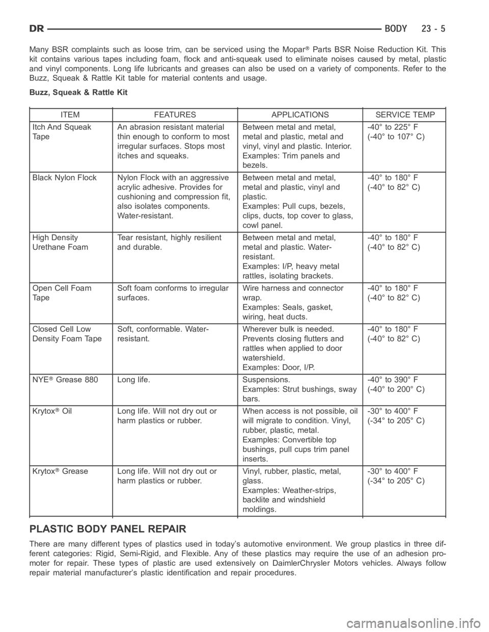
Many BSR complaints such as loose trim, can be serviced using the MoparParts BSR Noise Reduction Kit. This
kit contains various tapes including foam, flock and anti-squeak used to eliminate noises caused by metal, plastic
and vinyl components. Long life lubricants and greases can also be used on avariety of components. Refer to the
Buzz, Squeak & Rattle Kit table for material contents and usage.
Buzz, Squeak & Rattle Kit
ITEM FEATURES APPLICATIONS SERVICE TEMP
Itch And Squeak
TapeAn abrasion resistant material
thin enough to conform to most
irregular surfaces. Stops most
itches and squeaks.Between metal and metal,
metal and plastic, metal and
vinyl, vinyl and plastic. Interior.
Examples: Trim panels and
bezels.-40° to 225° F
(-40° to 107° C)
Black Nylon Flock Nylon Flock with an aggressive
acrylic adhesive. Provides for
cushioning and compression fit,
also isolates components.
Water-resistant.Between metal and metal,
metal and plastic, vinyl and
plastic.
Examples: Pull cups, bezels,
clips, ducts, top cover to glass,
cowl panel.-40° to 180° F
(-40° to 82° C)
High Density
Urethane FoamTear resistant, highly resilient
and durable.Between metal and metal,
metal and plastic. Water-
resistant.
Examples: I/P, heavy metal
rattles, isolating brackets.-40° to 180° F
(-40° to 82° C)
Open Cell Foam
TapeSoft foam conforms to irregular
surfaces.Wire harness and connector
wrap.
Examples: Seals, gasket,
wiring, heat ducts.-40° to 180° F
(-40° to 82° C)
Closed Cell Low
Density Foam TapeSoft, conformable. Water-
resistant.Wherever bulk is needed.
Prevents closing flutters and
rattles when applied to door
watershield.
Examples: Door, I/P.-40° to 180° F
(-40° to 82° C)
NYE
Grease 880 Long life. Suspensions.
Examples: Strut bushings, sway
bars.-40° to 390° F
(-40° to 200° C)
Krytox
Oil Long life. Will not dry out or
harm plastics or rubber.When access is not possible, oil
will migrate to condition. Vinyl,
rubber, plastic, metal.
Examples: Convertible top
bushings, pull cups trim panel
inserts.-30° to 400° F
(-34° to 205° C)
Krytox
Grease Long life. Will not dry out or
harm plastics or rubber.Vinyl, rubber, plastic, metal,
glass.
Examples: Weather-strips,
backlite and windshield
moldings.-30° to 400° F
(-34° to 205° C)
PLASTIC BODY PANEL REPAIR
There are many different types of plastics used in today’s automotive environment. We group plastics in three dif-
ferent categories: Rigid, Semi-Rigid, and Flexible. Any of these plastics may require the use of an adhesion pro-
moter for repair. These types of plastic are used extensively on DaimlerChrysler Motors vehicles. Always follow
repair material manufacturer’s plastic identification and repair procedures.
Page 4610 of 5267
The motor/module is programmed to learn the speed required to drive the panel based on position and recalibrates
itself as needed. If the sunroof becomes uncalibrated, it will only respond to the vent switch. If the vent switch is
pressed, the glass will move toward vent; if the switch is released, all motion stops. In the event that the sunroof
system becomes uncalibrated performthe sunroof position calibration procedure, (Refer to 8 - ELECTRICAL/
POWER TOP/MOTOR - STANDARD PROCEDURE -SUNROOF POSITION CALIBRATION).
DIAGNOSIS AND TESTING
POWER TOP - SUNROOF
Any diagnosis of the power sunroof system should begin with the use of a scantool and the proper Diagnostic
Procedures Information. The scan tool can provide confirmation that the Controller Area Network (CAN) Data Bus is
functional, that all of the electronic modules are sending and receiving the proper messages on the CAN Data Bus,
and that the power sunroof motor is being sent the proper hard wired output by the sunroof switch.
For complete circuit diagrams, refer to the appropriate wiring information. The wiring information includes wiring dia-
grams, proper wire and connector repair procedures, details of wire harness routing and retention, connector pin-out
information and location views for the various wire harness connectors, splices and grounds.
Refer to the appropriate diagnostic information.
SUNROOF
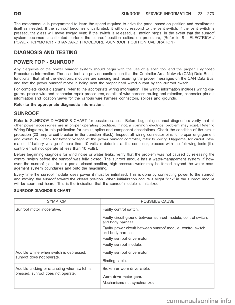
Refer to SUNROOF DIAGNOSIS CHART for possible causes. Before beginning sunroof diagnostics verify that all
other power accessories are in proper operating condition. If not, a common electrical problem may exist. Refer to
Wiring Diagrams, in this publication for circuit, splice and component descriptions. Check the condition of the circuit
protection (20 amp circuit breaker in the Junction Block). Inspect all wiring connector pins for proper engagement
and continuity. Check for battery voltage at the power sunroof controller, refer to Wiring Diagrams, for circuit infor-
mation. If battery voltage of more than 10 volts is detected at the controller, proceed with the following tests (the
controller will not operate at less than 10 volts).
Before beginning diagnosis for wind noise or water leaks, verify that the problem was not caused by releasing the
control switch before the sunroof was fully closed. The sunroof module hasa water-management system. If how-
ever, the sunroof glass is in a partial closed position, high pressure water may be forced beyond the water man-
agement system boundariesand onto the headlining.
Every time the sunroof module loses power it must be initialized. This is done by connecting power to the sunroof
and moving the sunroof toward the closed position. When initialization occurs a slight “kick” in the sunroof module
will be seen and heard. This is the indication that the sunroof module is initialized
SUNROOF DIAGNOSIS CHART
SYMPTOM POSSIBLE CAUSE
Sunroof motor inoperative. Faulty control switch.
Faulty circuit ground between sunroof module, control switch,
and body harness.
Faulty power circuit between sunroof module, control switch,
and body harness.
Faulty sunroof drive motor.
Faulty sunroof module.
Audible whine when switch is depressed,
sunroof does not operate.Faulty sunroof drive motor.
Binding cable.
Audible clicking or ratcheting when switch is
pressed, sunroof does not operate.Broken or worn drive cable.
Worn drive motor gear.
Mechanisms not synchronized.
Page 4660 of 5267
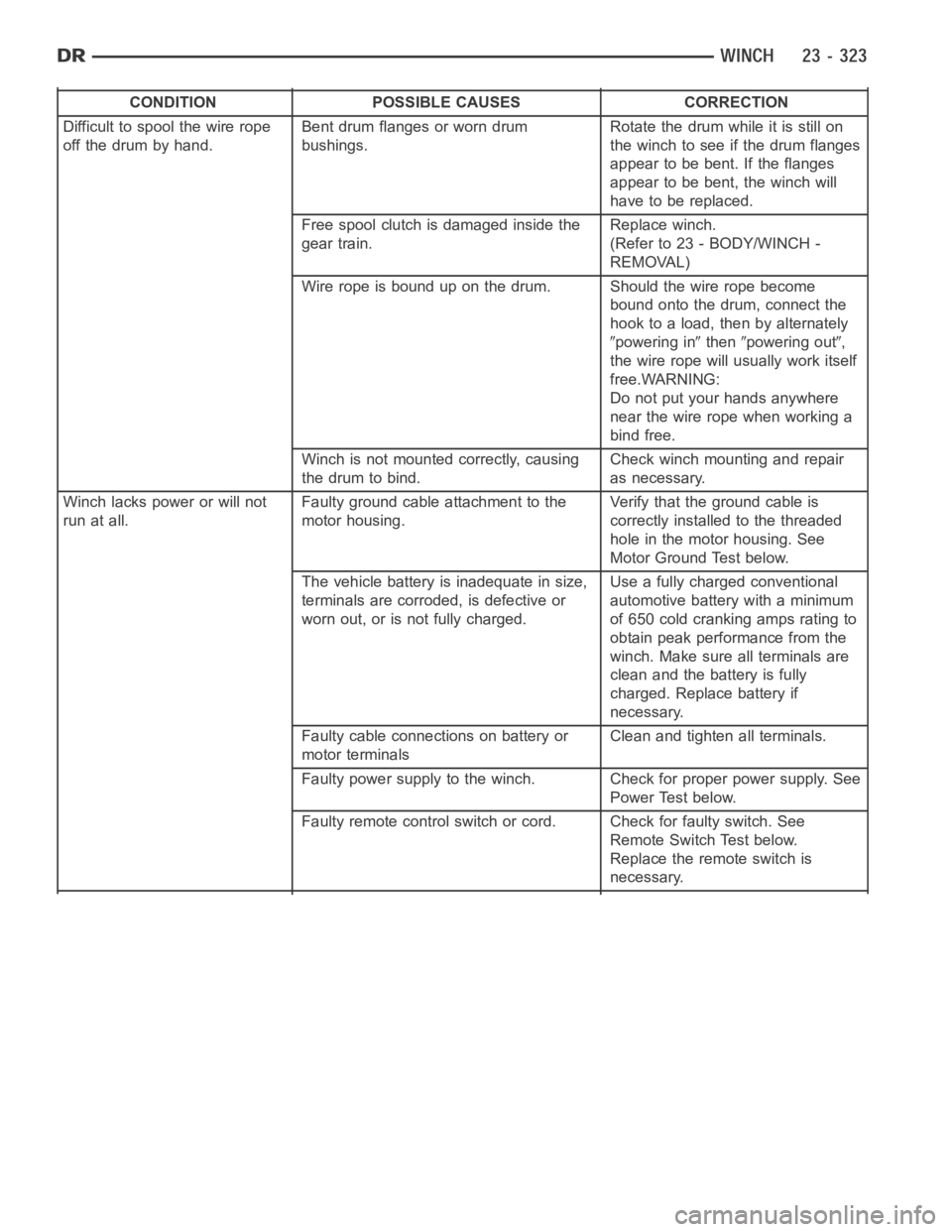
CONDITION POSSIBLE CAUSES CORRECTION
Difficult to spool the wire rope
off the drum by hand.Bent drum flanges or worn drum
bushings.Rotate the drum while it is still on
the winch to see if the drum flanges
appear to be bent. If the flanges
appear to be bent, the winch will
have to be replaced.
Free spool clutch is damaged inside the
gear train.Replace winch.
(Refer to 23 - BODY/WINCH -
REMOVAL)
Wire rope is bound up on the drum. Should the wire rope become
bound onto the drum, connect the
hook to a load, then by alternately
powering inthenpowering out,
the wire rope will usually work itself
free.WARNING:
Do not put your hands anywhere
near the wire rope when working a
bind free.
Winch is not mounted correctly, causing
the drum to bind.Check winch mounting and repair
as necessary.
Winch lacks power or will not
run at all.Faulty ground cable attachment to the
motor housing.Verify that the ground cable is
correctly installed to the threaded
hole in the motor housing. See
Motor Ground Test below.
The vehicle battery is inadequate in size,
terminals are corroded, is defective or
worn out, or is not fully charged.Use a fully charged conventional
automotive battery with a minimum
of650coldcrankingampsratingto
obtain peak performance from the
winch. Make sure all terminals are
clean and the battery is fully
charged. Replace battery if
necessary.
Faulty cable connections on battery or
motor terminalsClean and tighten all terminals.
Faulty power supply to the winch. Check for proper power supply. See
Power Test below.
Faulty remote control switch or cord. Check for faulty switch. See
Remote Switch Test below.
Replace the remote switch is
necessary.
Page 4842 of 5267
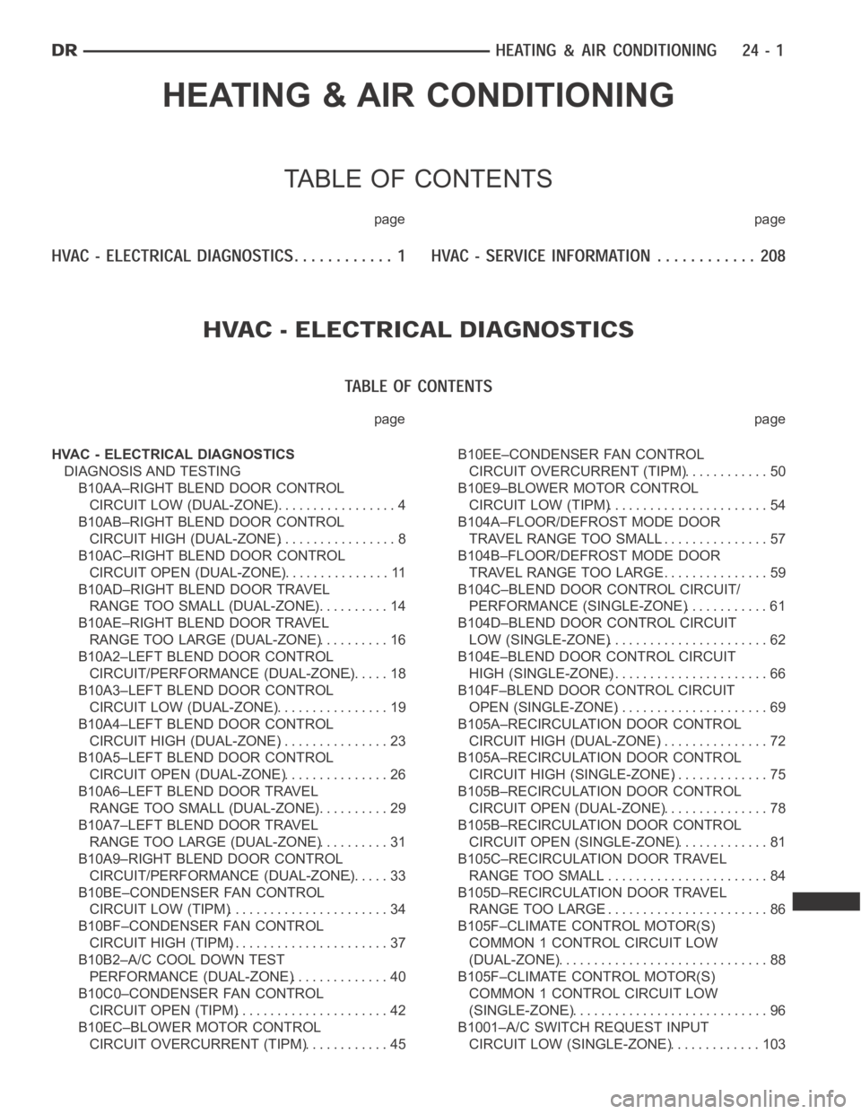
HEATING & AIR CONDITIONING
TABLE OF CONTENTS
page page
page page
HVAC - ELECTRICAL DIAGNOSTICS
DIAGNOSIS AND TESTING
B10AA–RIGHT BLEND DOOR CONTROL
CIRCUIT LOW (DUAL-ZONE).................. 4
B10AB–RIGHT BLEND DOOR CONTROL
CIRCUIT HIGH (DUAL-ZONE)................. 8
B10AC–RIGHT BLEND DOOR CONTROL
CIRCUIT OPEN (DUAL-ZONE)................ 11
B10AD–RIGHT BLEND DOOR TRAVEL
RANGE TOO SMALL (DUAL-ZONE)........... 14
B10AE–RIGHT BLEND DOOR TRAVEL
RANGE TOO LARGE (DUAL-ZONE).......... 16
B10A2–LEFT BLEND DOOR CONTROL
CIRCUIT/PERFORMANCE (DUAL-ZONE)...... 18
B10A3–LEFT BLEND DOOR CONTROL
CIRCUIT LOW (DUAL-ZONE)................. 19
B10A4–LEFT BLEND DOOR CONTROL
CIRCUIT HIGH (DUAL-ZONE)................ 23
B10A5–LEFT BLEND DOOR CONTROL
CIRCUIT OPEN (DUAL-ZONE)................ 26
B10A6–LEFT BLEND DOOR TRAVEL
RANGE TOO SMALL (DUAL-ZONE)........... 29
B10A7–LEFT BLEND DOOR TRAVEL
RANGE TOO LARGE (DUAL-ZONE).......... 31
B10A9–RIGHT BLEND DOOR CONTROL
CIRCUIT/PERFORMANCE (DUAL-ZONE)...... 33
B10BE–CONDENSER FAN CONTROL
CIRCUIT LOW (TIPM)....................... 34
B10BF–CONDENSER FAN CONTROL
CIRCUIT HIGH (TIPM)....................... 37
B10B2–A/C COOL DOWN TEST
PERFORMANCE (DUAL-ZONE).............. 40
B10C0–CONDENSER FAN CONTROL
CIRCUIT OPEN (TIPM)...................... 42
B10EC–BLOWER MOTOR CONTROL
CIRCUIT OVERCURRENT (TIPM)............. 45B10EE–CONDENSER FAN CONTROL
CIRCUIT OVERCURRENT (TIPM)............. 50
B10E9–BLOWER MOTOR CONTROL
CIRCUIT LOW (TIPM)....................... 54
B104A–FLOOR/DEFROST MODE DOOR
TRAVEL RANGE TOO SMALL................ 57
B104B–FLOOR/DEFROST MODE DOOR
TRAVEL RANGE TOO LARGE................ 59
B104C–BLEND DOOR CONTROL CIRCUIT/
PERFORMANCE (SINGLE-ZONE)............ 61
B104D–BLEND DOOR CONTROL CIRCUIT
LOW (SINGLE-ZONE)....................... 62
B104E–BLEND DOOR CONTROL CIRCUIT
HIGH (SINGLE-ZONE)....................... 66
B104F–BLEND DOOR CONTROL CIRCUIT
OPEN (SINGLE-ZONE)...................... 69
B105A–RECIRCULATION DOOR CONTROL
CIRCUIT HIGH (DUAL-ZONE)................ 72
B105A–RECIRCULATION DOOR CONTROL
CIRCUIT HIGH (SINGLE-ZONE).............. 75
B105B–RECIRCULATION DOOR CONTROL
CIRCUIT OPEN (DUAL-ZONE)................ 78
B105B–RECIRCULATION DOOR CONTROL
CIRCUIT OPEN (SINGLE-ZONE).............. 81
B105C–RECIRCULATION DOOR TRAVEL
RANGE TOO SMALL........................ 84
B105D–RECIRCULATION DOOR TRAVEL
RANGE TOO LARGE........................ 86
B105F–CLIMATE CONTROL MOTOR(S)
COMMON 1 CONTROL CIRCUIT LOW
(DUAL-ZONE)............................... 88
B105F–CLIMATE CONTROL MOTOR(S)
COMMON 1 CONTROL CIRCUIT LOW
(SINGLE-ZONE)............................. 96
B1001–A/C SWITCH REQUEST INPUT
CIRCUIT LOW (SINGLE-ZONE).............. 103