Page 3924 of 5267
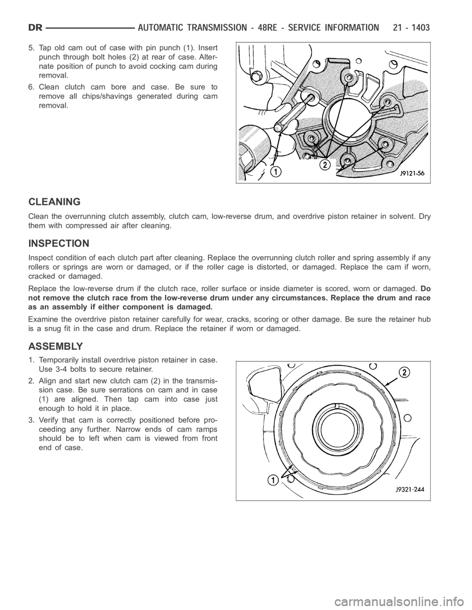
5. Tap old cam out of case with pin punch (1). Insert
punch through bolt holes (2) at rear of case. Alter-
nate position of punch to avoid cocking cam during
removal.
6. Clean clutch cam bore and case. Be sure to
remove all chips/shavings generated during cam
removal.
CLEANING
Clean the overrunning clutch assembly, clutch cam, low-reverse drum, andoverdrive piston retainer in solvent. Dry
them with compressed air after cleaning.
INSPECTION
Inspect condition of each clutch part after cleaning. Replace the overrunning clutch roller and spring assembly if any
rollers or springs are worn or damaged, or if the roller cage is distorted, or damaged. Replace the cam if worn,
cracked or damaged.
Replace the low-reverse drum if the clutch race, roller surface or inside diameter is scored, worn or damaged.Do
not remove the clutch race from the low-reverse drum under any circumstances. Replace the drum and race
as an assembly if either component is damaged.
Examine the overdrive piston retainer carefully for wear, cracks, scoring or other damage. Be sure the retainer hub
is a snug fit in the case and drum. Replace the retainer if worn or damaged.
ASSEMBLY
1. Temporarily install overdrive piston retainer in case.
Use 3-4 bolts to secure retainer.
2. Align and start new clutch cam (2) in the transmis-
sion case. Be sure serrations on cam and in case
(1) are aligned. Then tap cam into case just
enough to hold it in place.
3. Verify that cam is correctly positioned before pro-
ceeding any further. Narrow ends of cam ramps
should be to left when cam is viewed from front
end of case.
Page 3959 of 5267
VALVE-TORQUE CONVERTER DRAINBACK
DESCRIPTION
GAS ENGINES
The drainback valve is located in the transmission cooler outlet (pressure) line.
DIESEL ENGINE
The converter drainback check valve is located in the in the TOC pressure - supply line, between the engine
mounted TOC and the air to oil TOC.
OPERATION
GAS ENGINES
The valve prevents fluid from draining from the converter into the cooler and lines when the vehicle is shut down for
lengthy periods. Production valves have a hose nipple at one end, while theopposite end is threaded for a flare
fitting. All valves have an arrow (or similar mark) to indicate direction of flow through the valve.
DIESEL ENGINE
The valve prevents fluid from draining from the converter into the cooler and lines when the vehicle is shut down for
lengthy periods. Production valves have pipe thread on one end, while the opposite end is threaded for a flare
fitting, and are threaded into the oil cooler mounted on the side of the engine. All valves have an arrow (or similar
mark) to indicate direction of flow through the valve.
STANDARD PROCEDURE
GAS ENGINES
The converter drainback check valve is located in the cooler outlet (pressure) line near the radiator tank. The valve
prevents fluid drainback when the vehicle is parked for lengthy periods. The valve check ball is spring loaded and
has an opening pressure of approximately 2 psi.
The valve is serviced as an assembly; it is not repairable. Do not clean the valve if restricted, or contaminated by
sludge, or debris. If the valve fails, or if a transmission malfunction occurs that generates significant amounts of
sludge and/or clutch particles and metal shavings, the valve must be replaced.
If the valve is restricted, installed backwards, or in the wrong line, it will cause an transmission overheating condition
and possible transmission failure.
CAUTION: The drainback valve is a one-way flow device. It must be properly orientedintermsofflowdirec-
tion for the cooler to function properly. The valve must be installed in thepressure line. Otherwise flow will
be blocked and would cause an transmission overheating condition and eventual transmission failure.
DIESEL ENGINE
The converter drainback check valve is located in the in the TOC pressure - supply line, between the engine
mounted transmission oil cooler and the air to oil transmission oil cooler. The valve prevents fluid drainback when
the vehicle is parked for lengthy periods. The valve check ball is spring loaded and has an opening pressure of
approximately 2 psi.
The valve is serviced as an assembly; it is not repairable. Do not clean the valve if restricted, or contaminated by
sludge, or debris. If the valve fails, or if a transmission malfunction occurs that generates significant amounts of
sludge and/or clutch particles and metal shavings, the valve must be replaced.
If the valve is restricted, installed backwards, or in the wrong line, it will cause an transmission overheating condition
and possible transmission failure.
Page 4026 of 5267
7.(K977) MODE SELECT CIRCUIT OPEN
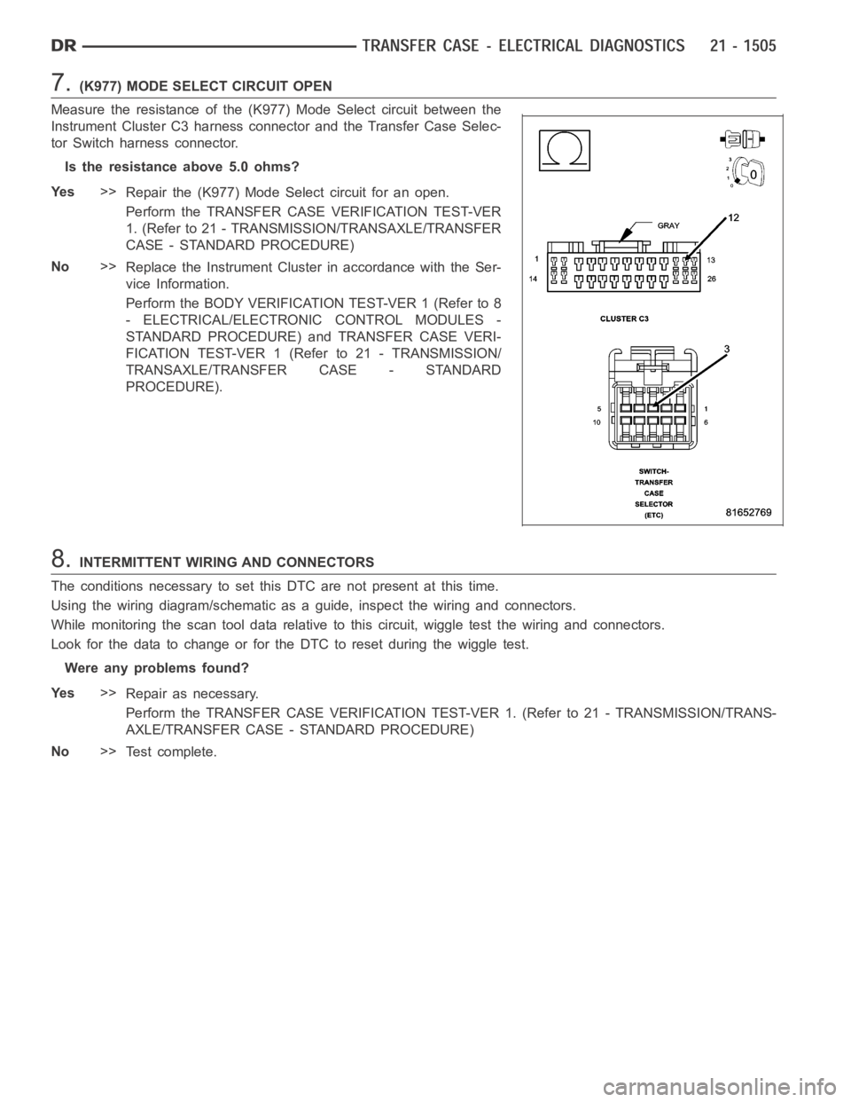
Measure the resistance of the (K977) Mode Select circuit between the
Instrument Cluster C3 harness connector and the Transfer Case Selec-
tor Switch harness connector.
Is the resistance above 5.0 ohms?
Ye s>>
Repair the (K977) Mode Select circuit for an open.
Perform the TRANSFER CASE VERIFICATION TEST-VER
1. (Refer to 21 - TRANSMISSION/TRANSAXLE/TRANSFER
CASE - STANDARD PROCEDURE)
No>>
Replace the Instrument Cluster in accordance with the Ser-
vice Information.
Perform the BODY VERIFICATION TEST-VER 1 (Refer to 8
- ELECTRICAL/ELECTRONIC CONTROL MODULES -
STANDARD PROCEDURE) and TRANSFER CASE VERI-
FICATION TEST-VER 1 (Refer to 21 - TRANSMISSION/
TRANSAXLE/TRANSFER CASE - STANDARD
PROCEDURE).
8.INTERMITTENT WIRING AND CONNECTORS
The conditions necessary to set this DTC are not present at this time.
Using the wiring diagram/schematic as a guide, inspect the wiring and connectors.
While monitoring the scan tool data relative to this circuit, wiggle test the wiring and connectors.
Look for the data to change or for the DTC to reset during the wiggle test.
Were any problems found?
Ye s>>
Repair as necessary.
Perform the TRANSFER CASE VERIFICATION TEST-VER 1. (Refer to 21 - TRANSMISSION/TRANS-
AXLE/TRANSFER CASE - STANDARD PROCEDURE)
No>>
Te s t c o m p l e t e .
Page 4028 of 5267
When Monitored:
With the ignition on.
Set Condition:
Transfer Case Range Select Switch voltage greater than 4.86 volts for 5 seconds
Possible Causes
(K77) 5 VOLT SELECTOR SWITCH SUPPLY CIRCUIT SHORTED TO VOLTAGE
(K977) MODE SELECT CIRCUIT SHORTED TO VOLTAGE
(K977) MODE SELECT CIRCUIT OPEN
(Z905) TRANSFER CASE SELECTOR SWITCH GROUND CIRCUIT OPEN
TRANSFER CASE SELECTOR SWITCH
INSTRUMENT CLUSTER
Diagnostic Test
1.TCASE SWITCH VOLTAGE ABOVE 4.8 VOLTS
Ignition on, engine not running.
With the scan tool under Instrument Cluster, read the Transfer Case Switchvoltage.
Is the volage above 4.8 volts?
Ye s>>
Go To 2
No>>
Go to 8
2.(K77) 5 VOLT SELECTOR SWITCH SUPPLY CIRCUIT SHORTED TO VOLTAGE
Turn the ignition off to the lock position.
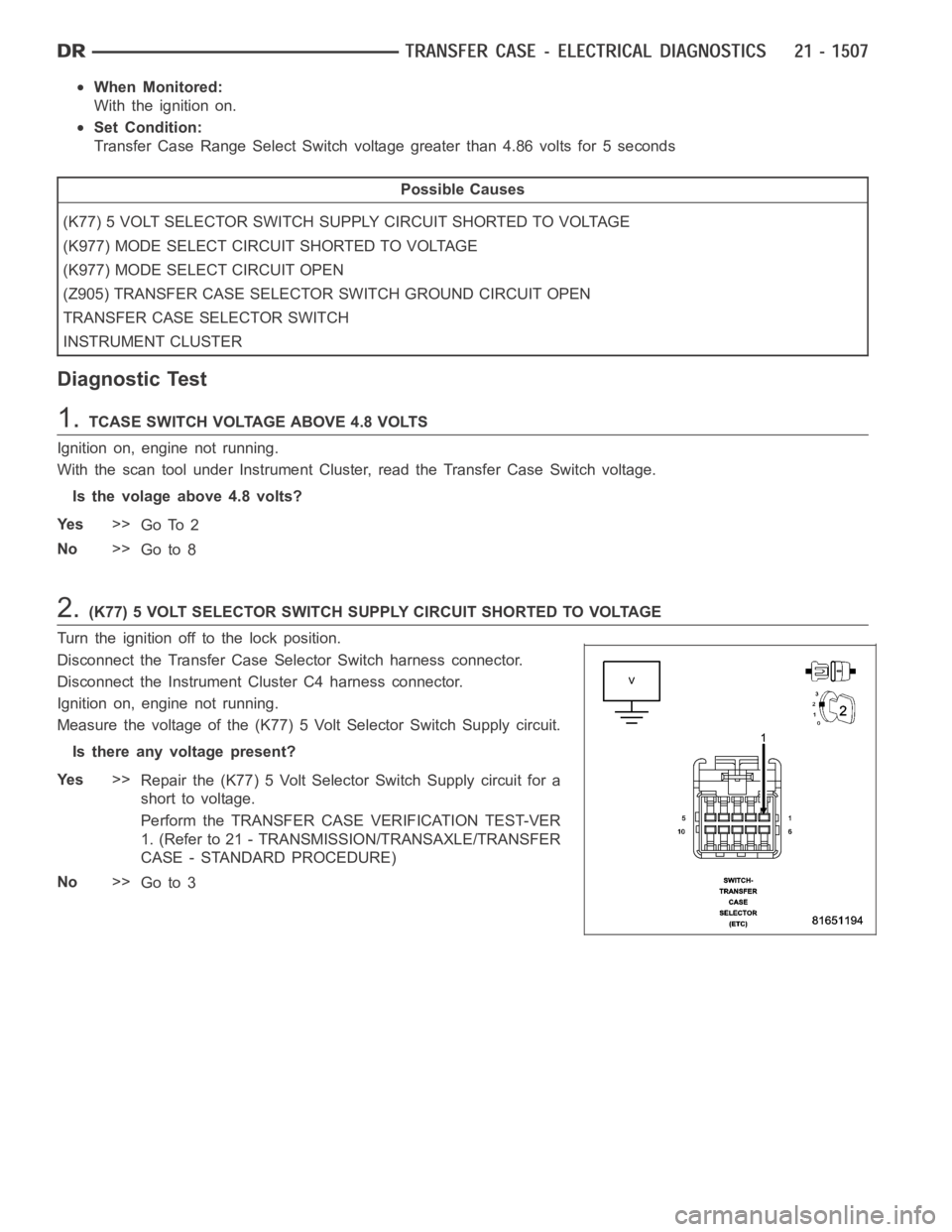
Disconnect the Transfer Case Selector Switch harness connector.
Disconnect the Instrument Cluster C4 harness connector.
Ignition on, engine not running.
Measure the voltage of the (K77) 5 Volt Selector Switch Supply circuit.
Is there any voltage present?
Ye s>>
Repair the (K77) 5 Volt Selector Switch Supply circuit for a
short to voltage.
Perform the TRANSFER CASE VERIFICATION TEST-VER
1. (Refer to 21 - TRANSMISSION/TRANSAXLE/TRANSFER
CASE - STANDARD PROCEDURE)
No>>
Go to 3
Page 4031 of 5267
7.INSTRUMENT CLUSTER
Repair
Replace the Instrument Cluster in accordance with the Service Information.
Perform the BODY VERIFICATION TEST-VER 1 (Refer to 8 - ELECTRICAL/ELECTRONIC CONTROL
MODULES - STANDARD PROCEDURE) and TRANSFER CASE VERIFICATION TEST-VER 1 (Refer to
21 - TRANSMISSION/TRANSAXLE/TRANSFER CASE - STANDARD PROCEDURE).
8.INTERMITTENT WIRING AND CONNECTORS
The conditions necessary to set this DTC are not present at this time.
Using the wiring diagram/schematic as a guide, inspect the wiring and connectors.
While monitoring the scan tool data relative to this circuit, wiggle test the wiring and connectors.
Look for the data to change or for the DTC to reset during the wiggle test.
Were any problems found?
Ye s>>
Repair as necessary.
Perform the TRANSFER CASE VERIFICATION TEST-VER 1. (Refer to 21 - TRANSMISSION/TRANS-
AXLE/TRANSFER CASE - STANDARD PROCEDURE)
No>>
Te s t c o m p l e t e .
Page 4035 of 5267
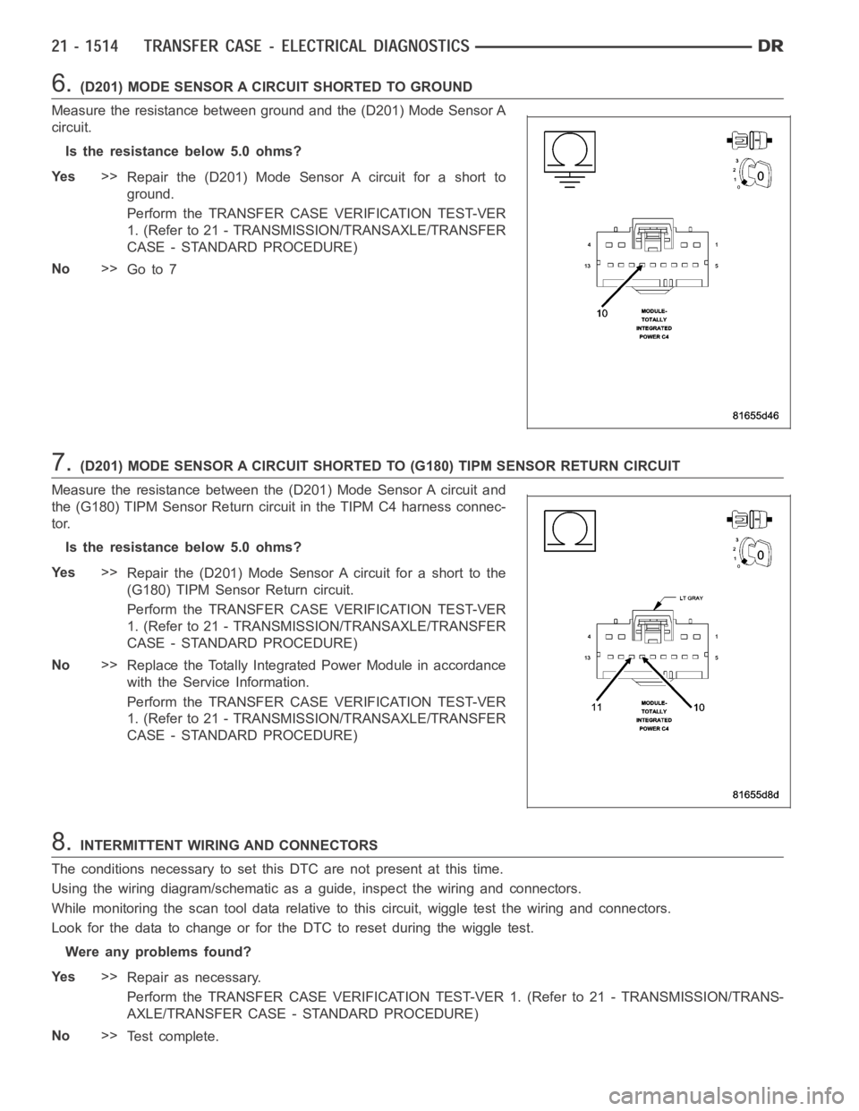
6.(D201) MODE SENSOR A CIRCUIT SHORTED TO GROUND
Measure the resistance between ground and the (D201) Mode Sensor A
circuit.
Is the resistance below 5.0 ohms?
Ye s>>
Repair the (D201) Mode Sensor A circuit for a short to
ground.
Perform the TRANSFER CASE VERIFICATION TEST-VER
1. (Refer to 21 - TRANSMISSION/TRANSAXLE/TRANSFER
CASE - STANDARD PROCEDURE)
No>>
Go to 7
7.(D201) MODE SENSOR A CIRCUIT SHORTED TO (G180) TIPM SENSOR RETURN CIRCUIT
Measure the resistance between the (D201) Mode Sensor A circuit and
the (G180) TIPM Sensor Return circuit in the TIPM C4 harness connec-
tor.
Is the resistance below 5.0 ohms?
Ye s>>
Repair the (D201) Mode Sensor A circuit for a short to the
(G180) TIPM Sensor Return circuit.
Perform the TRANSFER CASE VERIFICATION TEST-VER
1. (Refer to 21 - TRANSMISSION/TRANSAXLE/TRANSFER
CASE - STANDARD PROCEDURE)
No>>
Replace the Totally Integrated Power Module in accordance
with the Service Information.
Perform the TRANSFER CASE VERIFICATION TEST-VER
1. (Refer to 21 - TRANSMISSION/TRANSAXLE/TRANSFER
CASE - STANDARD PROCEDURE)
8.INTERMITTENT WIRING AND CONNECTORS
The conditions necessary to set this DTC are not present at this time.
Using the wiring diagram/schematic as a guide, inspect the wiring and connectors.
While monitoring the scan tool data relative to this circuit, wiggle test the wiring and connectors.
Look for the data to change or for the DTC to reset during the wiggle test.
Were any problems found?
Ye s>>
Repair as necessary.
Perform the TRANSFER CASE VERIFICATION TEST-VER 1. (Refer to 21 - TRANSMISSION/TRANS-
AXLE/TRANSFER CASE - STANDARD PROCEDURE)
No>>
Te s t c o m p l e t e .
Page 4037 of 5267
When Monitored:
With the ignition on. Battery voltage between 9.0 and 16.0 volts
Set Condition:
The TIPM detects 5.0 volts on the Transfer Case Range Position Sensor Signal circuit for 2.0 seconds when
voltage should not be present.
Possible Causes
(T103) 5 VOLT SUPPLY CIRCUIT SHORTED TO VOLTAGE
(D201) MODE SENSOR A CIRCUIT SHORTED TO VOLTAGE
(D201) MODE SENSOR A CIRCUIT OPEN
(G180) TIPM SENSOR RETURN CIRCUIT OPEN
SHIFT MOTOR/MODE SENSOR ASSEMBLY
TOTALLY INTEGRATED POWER MODULE (TIPM)
Diagnostic Test
1.T-CASE POSITION SENSOR VOLTAGE ABOVE 4.8 VOLTS
Ignition on, engine not running.
With the scan tool under TIPM, read the T-Case Position sensor voltage.
Is the voltage above 4.8 volts?
Ye s>>
Go To 2
No>>
Go to 7
2.(T103) 5 VOLT SUPPLY CIRCUIT SHORTED TO VOLTAGE
Turn the ignition off to the lock position.
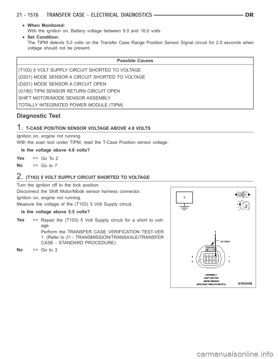
Disconnect the Shift Motor/Mode sensor harness connector.
Ignition on, engine not running.
Measure the voltage of the (T103) 5 Volt Supply circuit.
Is the voltage above 5.5 volts?
Ye s>>
Repair the (T103) 5 Volt Supply circuit for a short to volt-
age.
Perform the TRANSFER CASE VERIFICATION TEST-VER
1. (Refer to 21 - TRANSMISSION/TRANSAXLE/TRANSFER
CASE - STANDARD PROCEDURE)
No>>
Go to 3
Page 4040 of 5267
7.INTERMITTENT WIRING AND CONNECTORS
The conditions necessary to set this DTC are not present at this time.
Using the wiring diagram/schematic as a guide, inspect the wiring and connectors.
While monitoring the scan tool data relative to this circuit, wiggle test the wiring and connectors.
Look for the data to change or for the DTC to reset during the wiggle test.
Were any problems found?
Ye s>>
Repair as necessary.
Perform the TRANSFER CASE VERIFICATION TEST-VER 1. (Refer to 21 - TRANSMISSION/TRANS-
AXLE/TRANSFER CASE - STANDARD PROCEDURE)
No>>
Te s t c o m p l e t e .