2006 DODGE RAM SRT-10 air condition
[x] Cancel search: air conditionPage 3811 of 5267
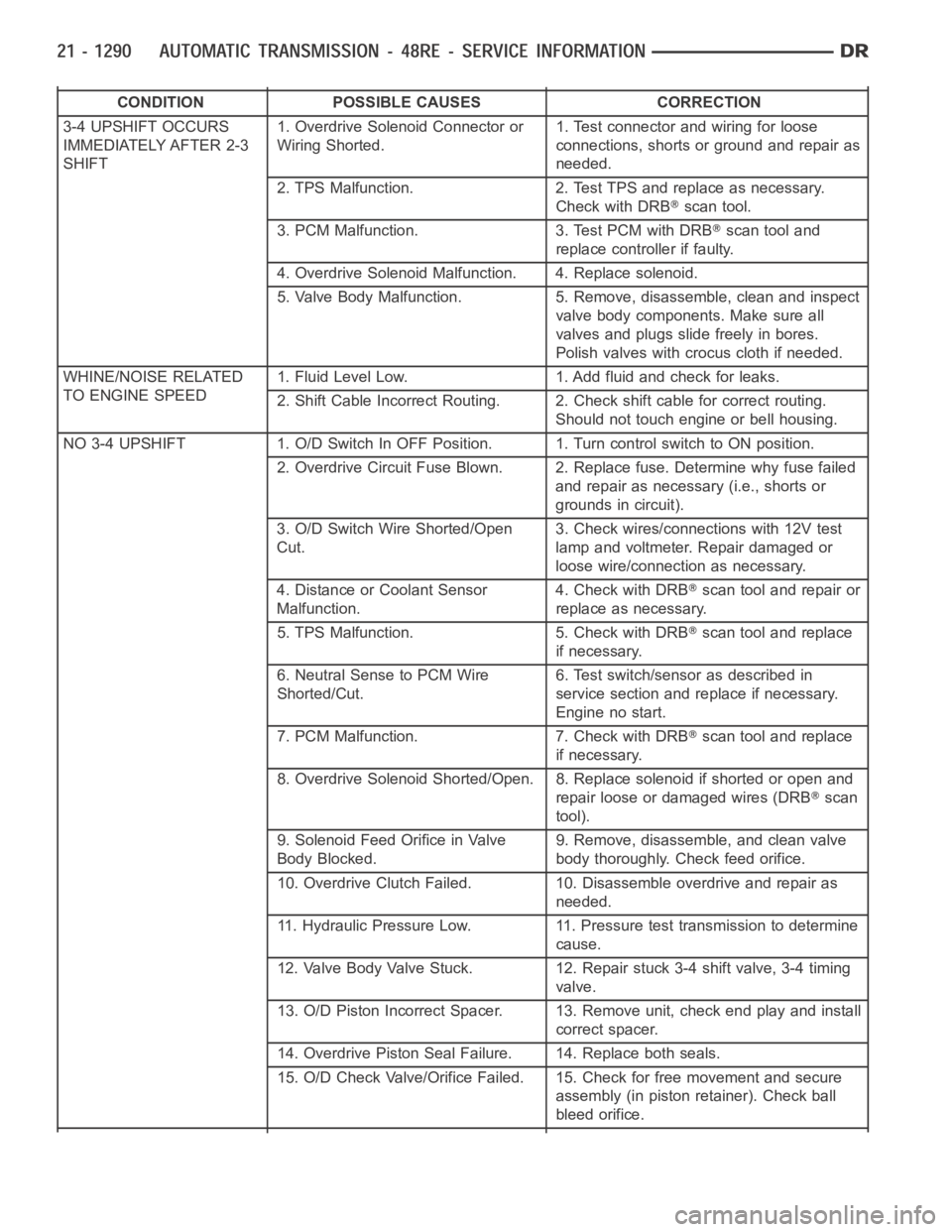
CONDITION POSSIBLE CAUSES CORRECTION
3-4 UPSHIFT OCCURS
IMMEDIATELY AFTER 2-3
SHIFT1. Overdrive Solenoid Connector or
Wiring Shorted.1. Test connector and wiring for loose
connections, shorts or ground and repair as
needed.
2. TPS Malfunction. 2. Test TPS and replace as necessary.
Check with DRB
scan tool.
3. PCM Malfunction. 3. Test PCM with DRB
scan tool and
replace controller if faulty.
4. Overdrive Solenoid Malfunction. 4. Replace solenoid.
5. Valve Body Malfunction. 5. Remove, disassemble, clean and inspect
valve body components. Make sure all
valves and plugs slide freely in bores.
Polish valves with crocus cloth if needed.
WHINE/NOISE RELATED
TO ENGINE SPEED1. Fluid Level Low. 1. Add fluid and check for leaks.
2. Shift Cable Incorrect Routing. 2. Check shift cable for correct routing.
Should not touch engine or bell housing.
NO3-4UPSHIFT 1.O/DSwitchInOFFPosition. 1.TurncontrolswitchtoONposition.
2. Overdrive Circuit Fuse Blown. 2. Replace fuse. Determine why fuse failed
and repair as necessary (i.e., shorts or
grounds in circuit).
3. O/D Switch Wire Shorted/Open
Cut.3. Check wires/connections with 12V test
lamp and voltmeter. Repair damaged or
loose wire/connection as necessary.
4. Distance or Coolant Sensor
Malfunction.4. Check with DRB
scan tool and repair or
replace as necessary.
5. TPS Malfunction. 5. Check with DRB
scan tool and replace
if necessary.
6. Neutral Sense to PCM Wire
Shorted/Cut.6. Test switch/sensor as described in
service section and replace if necessary.
Engine no start.
7. PCM Malfunction. 7. Check with DRB
scan tool and replace
if necessary.
8. Overdrive Solenoid Shorted/Open. 8. Replace solenoid if shorted or openand
repair loose or damaged wires (DRB
scan
tool).
9. Solenoid Feed Orifice in Valve
Body Blocked.9. Remove, disassemble, and clean valve
body thoroughly. Check feed orifice.
10. Overdrive Clutch Failed. 10. Disassemble overdrive and repair as
needed.
11. Hydraulic Pressure Low. 11. Pressure test transmission to determine
cause.
12. Valve Body Valve Stuck. 12. Repair stuck 3-4 shift valve, 3-4 timing
valve.
13. O/D Piston Incorrect Spacer. 13. Remove unit, check end play and install
correct spacer.
14. Overdrive Piston Seal Failure. 14. Replace both seals.
15. O/D Check Valve/Orifice Failed. 15. Check for free movement and secure
assembly (in piston retainer). Check ball
bleed orifice.
Page 3812 of 5267
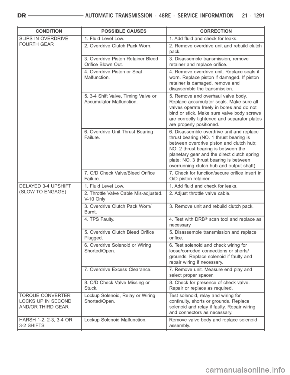
CONDITION POSSIBLE CAUSES CORRECTION
SLIPS IN OVERDRIVE
FOURTH GEAR1. Fluid Level Low. 1. Add fluid and check for leaks.
2. Overdrive Clutch Pack Worn. 2. Remove overdrive unit and rebuild clutch
pack.
3. Overdrive Piston Retainer Bleed
Orifice Blown Out.3. Disassemble transmission, remove
retainer and replace orifice.
4. Overdrive Piston or Seal
Malfunction.4. Remove overdrive unit. Replace seals if
worn. Replace piston if damaged. If piston
retainer is damaged, remove and
disassemble the transmission.
5. 3-4 Shift Valve, Timing Valve or
Accumulator Malfunction.5. Remove and overhaul valve body.
Replace accumulator seals. Make sure all
valves operate freely in bores and do not
bind or stick. Make sure valve body screws
are correctly tightened and separator plates
are properly positioned.
6. Overdrive Unit Thrust Bearing
Failure.6. Disassemble overdrive unit and replace
thrust bearing (NO. 1 thrust bearing is
between overdrive piston and clutch hub;
NO. 2 thrust bearing is between the
planetary gear and the direct clutch spring
plate; NO. 3 thrust bearing is between
overrunning clutch hub and output shaft).
7. O/D Check Valve/Bleed Orifice
Failure.7. Check for function/secure orifice insert in
O/D piston retainer.
DELAYED 3-4 UPSHIFT
(SLOW TO ENGAGE)1. Fluid Level Low. 1. Add fluid and check for leaks.
2. Throttle Valve Cable Mis-adjusted.
V- 1 0 O n l y2. Adjust throttle valve cable.
3. Overdrive Clutch Pack Worn/
Burnt.3. Remove unit and rebuild clutch pack.
4. TPS Faulty. 4. Test with DRB
scan tool and replace as
necessary
5. Overdrive Clutch Bleed Orifice
Plugged.5. Disassemble transmission and replace
orifice.
6. Overdrive Solenoid or Wiring
Shorted/Open.6. Test solenoid and check wiring for
loose/corroded connections or shorts/
grounds. Replace solenoid if faulty and
repair wiring if necessary.
7. Overdrive Excess Clearance. 7. Remove unit. Measure end play and
select proper spacer.
8. O/D Check Valve Missing or
Stuck.8. Check for presence of check valve.
Repair or replace as required.
TORQUE CONVERTER
LOCKS UP IN SECOND
AND/OR THIRD GEARLockup Solenoid, Relay or Wiring
Shorted/Open.Test solenoid, relay and wiring for
continuity, shorts or grounds. Replace
solenoid and relay if faulty. Repair wiring
and connectors as necessary.
HARSH 1-2, 2-3, 3-4 OR
3-2 SHIFTSLockup Solenoid Malfunction. Remove valve body and replace solenoid
assembly.
Page 3813 of 5267
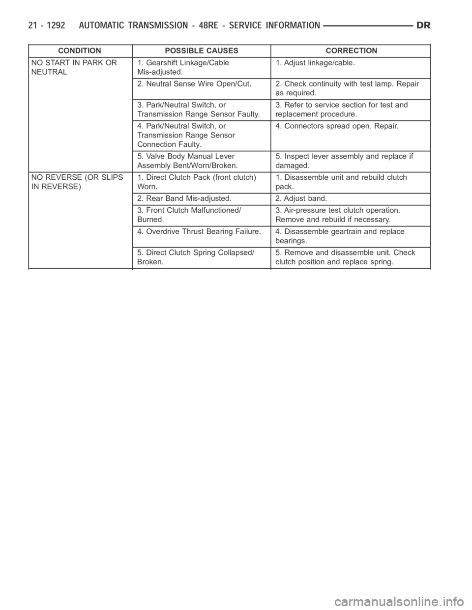
CONDITION POSSIBLE CAUSES CORRECTION
NO START IN PARK OR
NEUTRAL1. Gearshift Linkage/Cable
Mis-adjusted.1. Adjust linkage/cable.
2. Neutral Sense Wire Open/Cut. 2. Check continuity with test lamp. Repair
as required.
3. Park/Neutral Switch, or
Transmission Range Sensor Faulty.3. Refer to service section for test and
replacement procedure.
4. Park/Neutral Switch, or
Transmission Range Sensor
Connection Faulty.4. Connectors spread open. Repair.
5. Valve Body Manual Lever
Assembly Bent/Worn/Broken.5. Inspect lever assembly and replace if
damaged.
NO REVERSE (OR SLIPS
IN REVERSE)1. Direct Clutch Pack (front clutch)
Worn.1. Disassemble unit and rebuild clutch
pack.
2. Rear Band Mis-adjusted. 2. Adjust band.
3. Front Clutch Malfunctioned/
Burned.3. Air-pressure test clutch operation.
Remove and rebuild if necessary.
4. Overdrive Thrust Bearing Failure. 4. Disassemble geartrain and replace
bearings.
5. Direct Clutch Spring Collapsed/
Broken.5. Remove and disassemble unit. Check
clutch position and replace spring.
Page 3814 of 5267
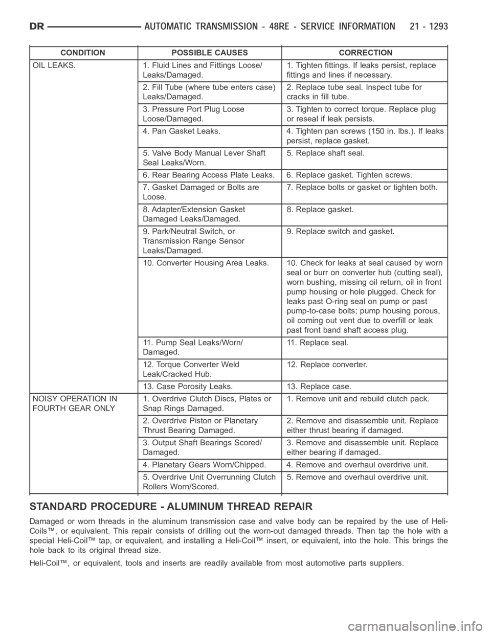
CONDITION POSSIBLE CAUSES CORRECTION
OIL LEAKS. 1. Fluid Lines and Fittings Loose/
Leaks/Damaged.1. Tighten fittings. If leaks persist, replace
fittings and lines if necessary.
2. Fill Tube (where tube enters case)
Leaks/Damaged.2. Replace tube seal. Inspect tube for
cracks in fill tube.
3. Pressure Port Plug Loose
Loose/Damaged.3. Tighten to correct torque. Replace plug
or reseal if leak persists.
4. Pan Gasket Leaks. 4. Tighten pan screws (150 in. lbs.). If leaks
persist, replace gasket.
5. Valve Body Manual Lever Shaft
Seal Leaks/Worn.5. Replace shaft seal.
6. Rear Bearing Access Plate Leaks. 6. Replace gasket. Tighten screws.
7. Gasket Damaged or Bolts are
Loose.7. Replace bolts or gasket or tighten both.
8. Adapter/Extension Gasket
Damaged Leaks/Damaged.8. Replace gasket.
9. Park/Neutral Switch, or
Transmission Range Sensor
Leaks/Damaged.9. Replace switch and gasket.
10. Converter Housing Area Leaks. 10. Check for leaks at seal caused by worn
seal or burr on converter hub (cutting seal),
worn bushing, missing oil return, oil in front
pump housing or hole plugged. Check for
leaks past O-ring seal on pump or past
pump-to-case bolts; pump housing porous,
oil coming out vent due to overfill or leak
past front band shaft access plug.
11. Pump Seal Leaks/Worn/
Damaged.11. Replace seal.
12. Torque Converter Weld
Leak/Cracked Hub.12. Replace converter.
13. Case Porosity Leaks. 13. Replace case.
NOISY OPERATION IN
FOURTH GEAR ONLY1. Overdrive Clutch Discs, Plates or
Snap Rings Damaged.1. Remove unit and rebuild clutch pack.
2. Overdrive Piston or Planetary
Thrust Bearing Damaged.2. Remove and disassemble unit. Replace
either thrust bearing if damaged.
3. Output Shaft Bearings Scored/
Damaged.3. Remove and disassemble unit. Replace
either bearing if damaged.
4. Planetary Gears Worn/Chipped. 4. Remove and overhaul overdrive unit.
5. Overdrive Unit Overrunning Clutch
Rollers Worn/Scored.5. Remove and overhaul overdrive unit.
STANDARD PROCEDURE - ALUMINUM THREAD REPAIR
DamagedorwornthreadsinthealuminumtransmissioncaseandvalvebodycanberepairedbytheuseofHeli-
Coils™, or equivalent. This repair consists of drilling out the worn-out damaged threads. Then tap the hole with a
special Heli-Coil™ tap, or equivalent, and installing a Heli-Coil™ insert, or equivalent, into the hole. This brings the
hole back to its original thread size.
Heli-Coil™, or equivalent, tools and inserts are readily available from most automotive parts suppliers.
Page 3827 of 5267
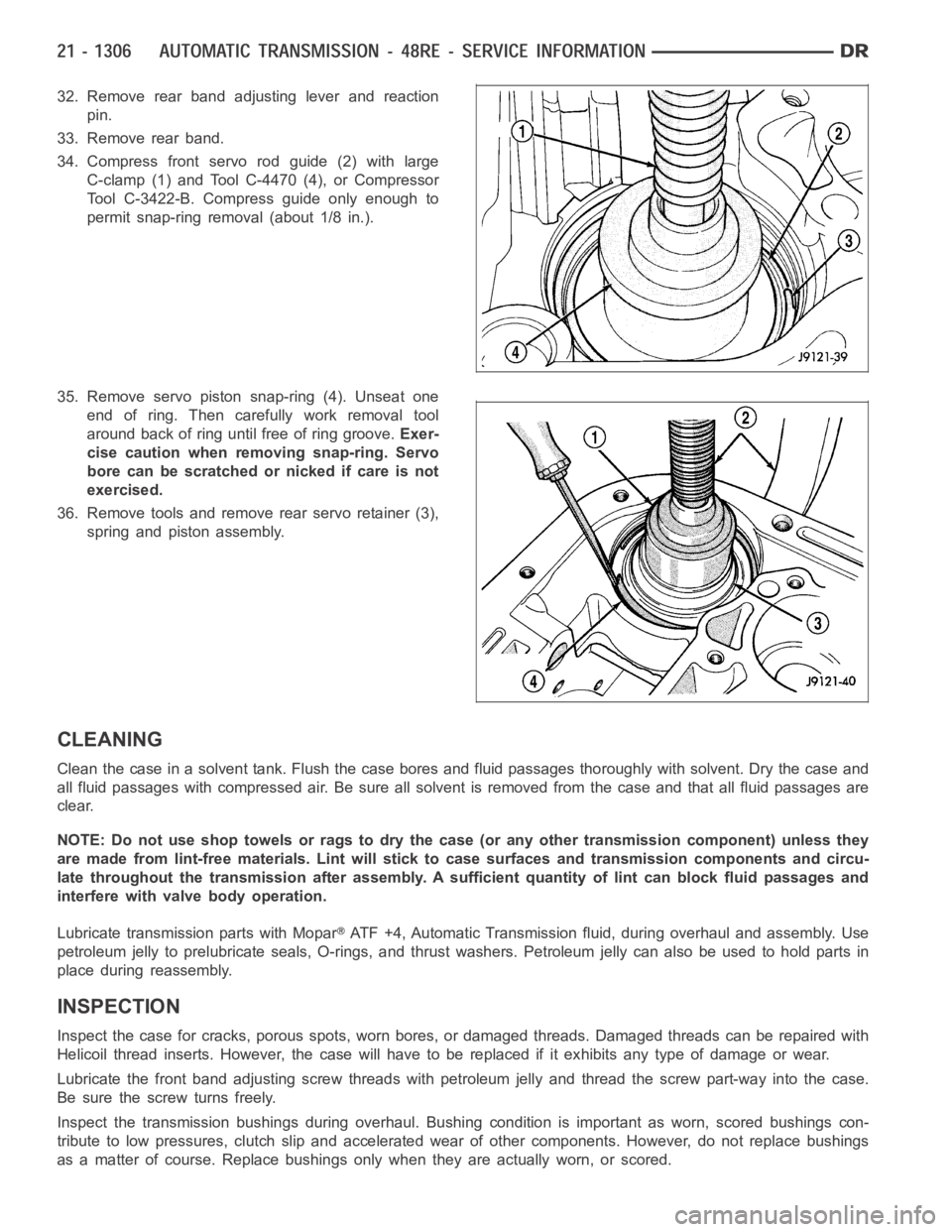
32. Remove rear band adjusting lever and reaction
pin.
33. Remove rear band.
34. Compress front servo rod guide (2) with large
C-clamp (1) and Tool C-4470 (4), or Compressor
Tool C-3422-B. Compress guide only enough to
permit snap-ring removal (about 1/8 in.).
35. Remove servo piston snap-ring (4). Unseat one
end of ring. Then carefully work removal tool
around back of ring until free of ring groove.Exer-
cise caution when removing snap-ring. Servo
bore can be scratched or nicked if care is not
exercised.
36. Remove tools and remove rear servo retainer (3),
spring and piston assembly.
CLEANING
Clean the case in a solvent tank. Flush the case bores and fluid passages thoroughly with solvent. Dry the case and
all fluid passages with compressed air. Be sure all solvent is removed fromthe case and that all fluid passages are
clear.
NOTE: Do not use shop towels or rags to dry the case (or any other transmission component) unless they
aremadefromlint-freematerials.Lintwillsticktocasesurfacesandtransmission components and circu-
late throughout the transmission after assembly. A sufficient quantity of lint can block fluid passages and
interfere with valve body operation.
Lubricate transmission parts with Mopar
ATF +4, Automatic Transmission fluid, during overhaul and assembly. Use
petroleum jelly to prelubricate seals, O-rings, and thrust washers. Petroleumjellycanalsobeusedtoholdpartsin
place during reassembly.
INSPECTION
Inspect the case for cracks, porous spots, worn bores, or damaged threads.Damaged threads can be repaired with
Helicoil thread inserts. However, the case will have to be replaced if it exhibits any type of damage or wear.
Lubricate the front band adjusting screw threads with petroleum jelly andthread the screw part-way into the case.
Be sure the screw turns freely.
Inspect the transmission bushings during overhaul. Bushing condition isimportant as worn, scored bushings con-
tribute to low pressures, clutch slipand accelerated wear of other components. However, do not replace bushings
as a matter of course. Replace bushings only when they are actually worn, orscored.
Page 3874 of 5267
FLUID AND FILTER
DIAGNOSIS AND TESTING
EFFECTS OF INCORRECT FLUID LEVEL
Alowfluidlevelallowsthepumptotakeinairalongwiththefluid.Airinthe fluid will cause fluid pressures to be
low and develop slower than normal. If the transmission is overfilled, thegears churn the fluid into foam. This aer-
ates the fluid and causing the same conditions occurring with a low level. In either case, air bubbles cause fluid
overheating, oxidation, and varnish buildup which interferes with valveand clutch operation. Foaming also causes
fluid expansion which can result in fluid overflow from the transmission vent or fill tube. Fluid overflow can easily be
mistaken for a leak if inspection is not careful.
CAUSES OF BURNT FLUID
Burnt, discolored fluid is a result of overheating which has two primary causes.
1. A result of restricted fluid flow through the main and/or auxiliary cooler. This condition is usually the result of a
faulty or improperly installed drainback valve, a damaged oil cooler, or severe restrictions in the coolers and lines
caused by debris or kinked lines.
2. Heavy duty operation with a vehicle not properly equipped for this type of operation. Trailer towing or similar high
load operation will overheat the transmission fluid if the vehicle is improperly equipped. Such vehicles should
have an auxiliary transmission fluid cooler, a heavy duty cooling system,and the engine/axle ratio combination
needed to handle heavy loads.
FLUID CONTAMINATION
Transmission fluid contamination is generally a result of:
adding incorrect fluid
failure to clean dipstick and fill tube when checking level
engine coolant entering the fluid
internal failure that generates debris
overheat that generates sludge (fluid breakdown)
failure to replace contaminated converter after repair
The use of non-recommended fluids can result in transmission failure. Theusual results are erratic shifts, slippage,
abnormal wear and eventual failure due to fluid breakdown and sludge formation. Avoid this condition by using rec-
ommended fluids only.
The dipstick cap and fill tube should be wiped clean before checking fluid level. Dirt, grease and other foreign mate-
rial on the cap and tube could fall into the tube if not removed beforehand. Take the time to wipe the cap and tube
clean before withdrawing the dipstick.
Engine coolant in the transmission fluid is generally caused by a cooler malfunction. The only remedy is to replace
the radiator as the cooler in the radiator is not a serviceable part. If coolant has circulated through the transmission,
an overhaul is necessary.
The torque converter should also be replaced whenever a failure generatessludge and debris. This is necessary
because normal converter flushing procedures will not remove all contaminants.
STANDARD PROCEDURE
FLUID LEVEL CHECK
Low fluid level can cause a variety of conditions because it allows the pumpto take in air along with the fluid. As
in any hydraulic system, air bubbles make the fluid spongy, therefore, pressures will be low and build up slowly.
Improper filling can also raise the fluid level too high. When the transmssion has too much fluid, the geartrain
churns up foam and cause the same conditions which occur with a low fluid level.
In either case, air bubbles can cause overheating and/or fluid oxidation,and varnishing. This can interfere with nor-
mal valve, clutch, and accumulator operation. Foaming can also result in fluid escaping from the transmission vent
where it may be mistaken for a leak.
Page 3892 of 5267
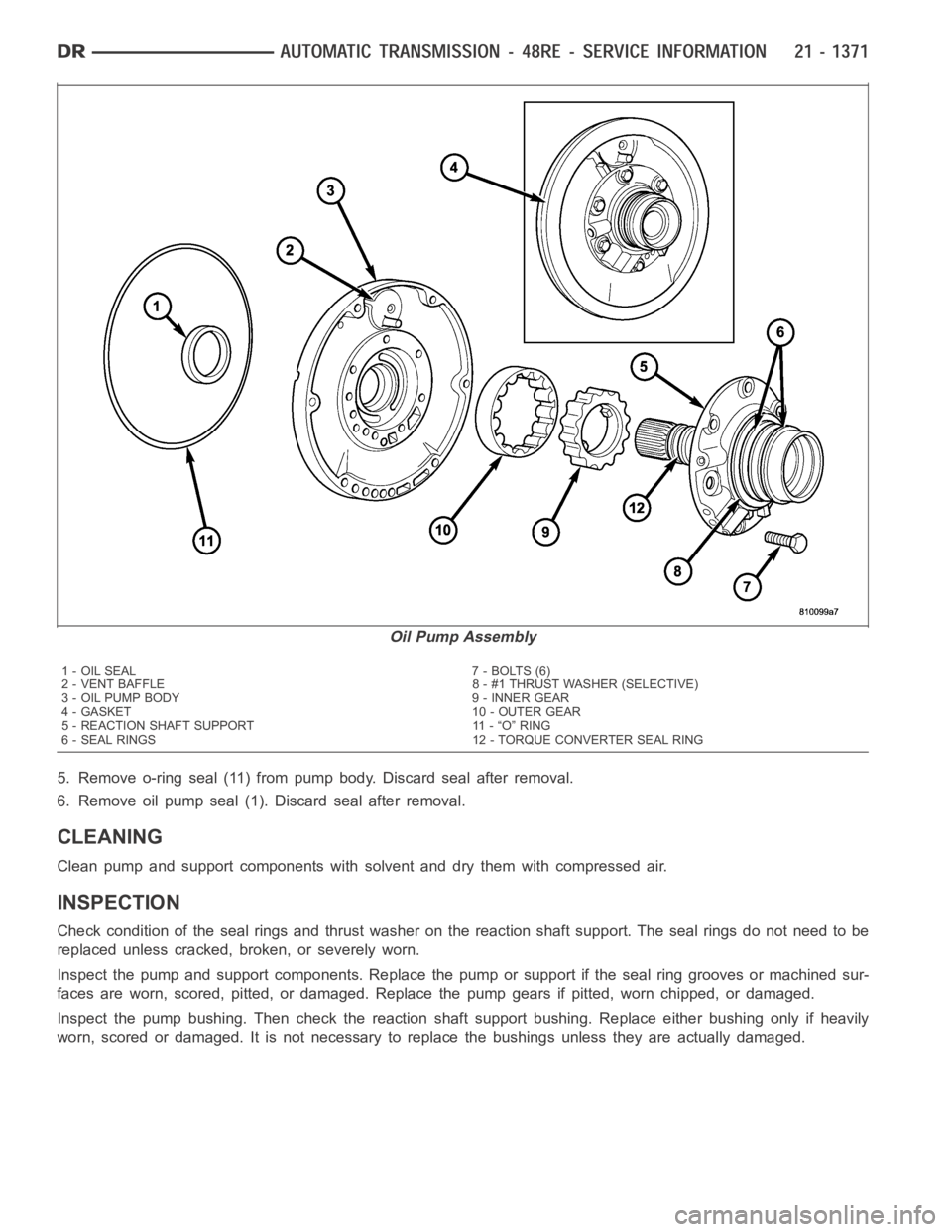
5. Remove o-ring seal (11) from pump body. Discard seal after removal.
6. Remove oil pump seal (1). Discard seal after removal.
CLEANING
Clean pump and support components with solvent and dry them with compressedair.
INSPECTION
Check condition of the seal rings and thrust washer on the reaction shaft support. The seal rings do not need to be
replaced unless cracked, broken, or severely worn.
Inspect the pump and support components. Replace the pump or support if theseal ring grooves or machined sur-
faces are worn, scored, pitted, or damaged. Replace the pump gears if pitted, worn chipped, or damaged.
Inspect the pump bushing. Then check the reaction shaft support bushing. Replace either bushing only if heavily
worn, scored or damaged. It is not necessary to replace the bushings unlessthey are actually damaged.
Oil Pump Assembly
1 - OIL SEAL 7 - BOLTS (6)
2 - VENT BAFFLE 8 - #1 THRUST WASHER (SELECTIVE)
3 - OIL PUMP BODY 9 - INNER GEAR
4 - GASKET 10 - OUTER GEAR
5 - REACTION SHAFT SUPPORT 11 - “O” RING
6 - SEAL RINGS 12 - TORQUE CONVERTER SEAL RING
Page 3910 of 5267
CLEANING
Clean the geartrain and case components with solvent. Dry all parts exceptthebearingswithcompressedair.Allow
bearings to air dry.
Do not use shop towels for wiping parts dry unless the towels are made from a lint-free material. A sufficient quan-
tity of lint (from shop towels, cloths, rags, etc.) could plug the transmission filter and fluid passages.
Discard the old case gasket and seals.Do not attempt to salvage these parts. They are not reusable. Replace any
of the overdrive unit snap-rings if distorted or damaged.
Minor nicks or scratches on components can be smoothed with crocus cloth. However, do not attempt to reduce
severescoringonanycomponentswithabrasive materials. Replace severely scored components; do not try to
salvage them.
INSPECTION
Check condition of the park lock components and the overdrive case.
Check the bushings in the overdrive case. Replace the bushings if severelyscored or worn. Also replace the case
seal if loose, distorted, or damaged.
Examine the overdrive and direct clutch discs and plates. Replace the discs if the facing is worn, severely scored,
or burned and flaking off. Replace the clutch plates if worn, heavily scored, or cracked. Check the lugs on the clutch
plates for wear. The plates should slide freely in the drum. Replace the plates or drum if binding occurs.
Check condition of the annulus gear, direct clutch hub, clutch drum and clutch spring. Replace the gear, hub and
drum if worn or damaged. Replace the spring if collapsed, distorted, or cracked.
Be sure the splines and lugs on the gear, drum and hub are in good condition. The clutch plates and discs should
slide freely in these components.
Inspect the thrust bearings and spring plate. Replace the plate if worn or scored. Replace the bearings if rough,
noisy, brinnelled, or worn.
Inspect the planetary gear assembly and the sun gear and bushings. If either the sun gear or the bushings are
damaged, replace the gear and bushings as an assembly. The gear and bushings are not serviced separately.
The planetary carrier and pinions must be in good condition. Also be sure the pinion pins are secure and in good
condition. Replace the carrier if worn or damaged.
Inspect the overrunning clutch and race. The race surface should be smoothand free of scores. Replace the over-
running clutch assembly or the race if either assembly is worn or damaged inany way.
Replace the shaft pilot bushing and inner bushing if damaged. Replace either shaft bearing if rough or noisy.
Replace the bearing snap-rings if distorted or cracked.
Check the machined surfaces on the output shaft. These surfaces should clean and smooth. Very minor nicks or
scratches can be smoothed with crocus cloth. Replace the shaft if worn, scored or damaged in any way.
Inspect the output shaft bushings. The small bushing is the intermediate shaft pilot bushing. The large bushing is the
overrunning clutch hub bushing. Replace either bushing if scored, pitted, cracked, or worn.