Page 3837 of 5267

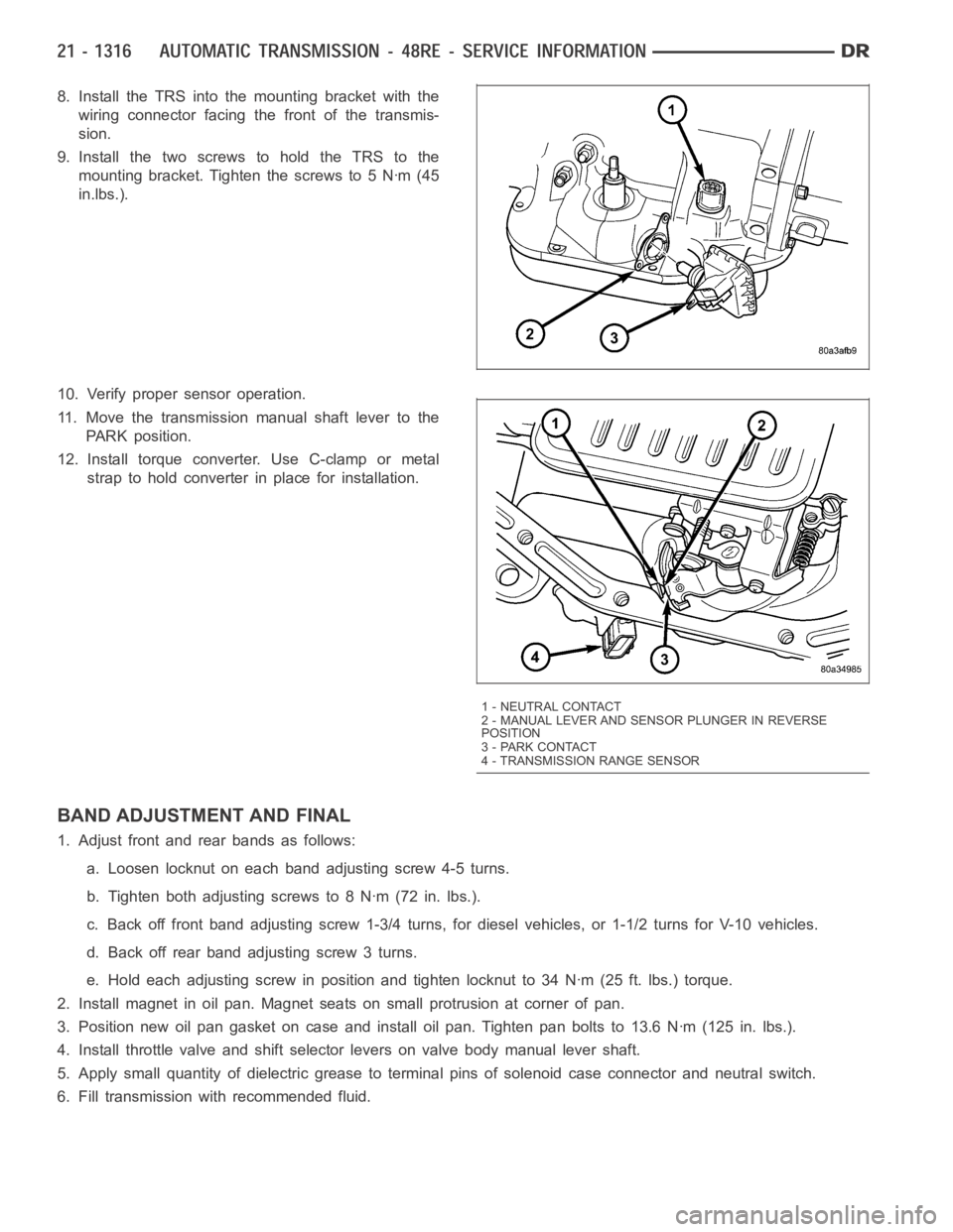
8. Install the TRS into the mounting bracket with the
wiring connector facing the front of the transmis-
sion.
9. Install the two screws to hold the TRS to the
mounting bracket. Tighten the screws to 5 Nꞏm (45
in.lbs.).
10. Verify proper sensor operation.
11. Move the transmission manual shaft lever to the
PARK position.
12. Install torque converter. Use C-clamp or metal
strap to hold converter in place for installation.
BAND ADJUSTMENT AND FINAL
1. Adjust front and rear bands as follows:
a. Loosen locknut on each band adjusting screw 4-5 turns.
b. Tighten both adjusting screws to 8 Nꞏm (72 in. lbs.).
c. Back off front band adjusting screw 1-3/4 turns, for diesel vehicles, or1-1/2 turns for V-10 vehicles.
d. Back off rear band adjusting screw 3 turns.
e. Hold each adjusting screw in position and tighten locknut to 34 Nꞏm (25 ft. lbs.) torque.
2. Install magnet in oil pan. Magnet seats on small protrusion at corner of pan.
3. Position new oil pan gasket on case and install oil pan. Tighten pan boltsto 13.6 Nꞏm (125 in. lbs.).
4. Install throttle valve and shift selector levers on valve body manual lever shaft.
5. Apply small quantity of dielectric grease to terminal pins of solenoid case connector and neutral switch.
6. Fill transmission with recommended fluid.
1 - NEUTRAL CONTACT
2 - MANUAL LEVER AND SENSOR PLUNGER IN REVERSE
POSITION
3 - PARK CONTACT
4 - TRANSMISSION RANGE SENSOR
Page 4007 of 5267

sharpness of these edges is vitally important. The edges prevent foreign matter from lodging between the valves
and plugs and the bore.
Inspect all the valve and plug bores in the valve body. Use a penlight to viewthe bore interiors. Replace the valve
body if any bores are distorted or scored. Inspect all of the valve body springs. The springs must be free of dis-
tortion, warpage or broken coils.
Check the two separator plates for distortion or damage of any kind. Inspect the upper housing, lower housing, 3-4
accumulator housing, and transfer plate carefully. Be sure all fluid passages are clean and clear. Check condition of
the upper housing and transfer plate check balls as well. The check balls and ball seats must not be worn or dam-
aged.
Trial fit each valve and plug in its bore to check freedom of operation. Whenclean and dry, the valves and plugs
shoulddropfreelyintothebores.
Valve body bores do not change dimensionally with use. If the valve body functioned correctly when new, it will
continue to operate properly after cleaning and inspection. It should notbe necessary to replace a valve body
assembly unless it is damaged in handling.
The only serviceable valve body components are listed below. The remaining valve body components are serviced
only as part of a complete valve body assembly. Serviceable parts are:
dual solenoid and harness assembly
solenoid gasket
solenoid case connector O-rings and shoulder bolt
switch valve and spring
pressure adjusting screw and bracket assembly
throttle lever
manual lever and shaft seal
throttle lever shaft seal, washer, and E-clip
fluid filter and screws
detent ball and spring
valve body screws
governor pressure solenoid
governor pressure sensor and retaining clip
park lock rod and E-clip
ASSEMBLY
CAUTION: Do not force valves or plugs into place during reassembly. If the valve body bores, valves and
plugs are free of distortion or burrs, the valve body components should allslide into place easily. In addi-
tion, do not overtighten the transfer plate and valve body screws during reassembly. Overtightening can
distort the housings resulting in valve sticking, cross leakage and unsatisfactory operation. Tighten valve
body screws to recommended torque only.
Page 4010 of 5267
3. Align and position upper housing separator plate
(3) on transfer plate (2).
4. Install brace plate (1). Tighten brace attaching
screws to 4 Nꞏm (35 in. lbs.) torque.
5. Install remaining separator plate attaching screws.
Tighten screws to 4 Nꞏm (35 in. lbs.) torque.
UPPER AND LOWER HOUSING
1. Position upper housing so internal passages and
check ball seats are facing upward. Then install
check balls in housing (1, 2). Seven check balls
are used. The single large check ball (2) is approx-
imately 8.7 mm (11/32 in.) diameter. The single
small check ball is approximately 4.8 mm (3/16 in.)
in diameter. The remaining 5 check balls are
approximately 6.3 mm (1/4 in.) in diameter.
2. Position assembled transfer plate and upper hous-
ing separator plate (2) on upper housing. Be sure
filter screen (1) is seated in proper housing recess.
Page 4338 of 5267

BODY
TABLE OF CONTENTS
page page
BODY
WARNING
SAFETY PRECAUTIONS AND WARNINGS ..... 2
DIAGNOSIS AND TESTING
WATER LEAKS .............................. 2
WIND NOISE ................................ 3
STANDARD PROCEDURE
BODY LUBRICATION ......................... 4
HEAT STAKING .............................. 4
BUZZ, SQUEAK & RATTLE ................... 4
PLASTIC BODY PANEL REPAIR ............... 5
SPECIFICATIONS
TORQUE ................................... 14
SPECIAL TOOLS
BODY ...................................... 16TA I L G AT E..............................17
DOOR - FRONT.........................28
DOORS - REAR.........................56
EXTERIOR.............................86
HOOD................................126
INSTRUMENT PANEL....................138
INTERIOR.............................176
PA I N T................................215
SEATS...............................221
STATIONARY GLASS....................256
SUNROOF - SERVICE INFORMATION.......270
WEATHERSTRIP/SEALS..................300
WINCH...............................320
BODY STRUCTURE.....................361
Page 4526 of 5267
CARPETS AND FLOOR MATS
REMOVAL
NOTE: Carpet for Quad Cab model shown. Regular cab similar.
1. Remove the front seats (Refer to 23 - BODY/
SEATS/SEAT - FRONT - REMOVAL).
2. If equipped, remove the floor console (Refer to 23 -
BODY/INTERIOR/FLOOR CONSOLE -
REMOVAL).
3. If equipped, remove the three bolts (1) that secure
the rear storage compartment (2) to the floor panel
(3) and remove the storage compartment from the
rear trim panel (4).
4. On Quad Cab models, remove the rear seats (1)
(Refer to 23 - BODY/SEATS/SEAT - REAR -
REMOVAL).
5. On Quad Cab models, remove the rear cup holder
(2) using a trim stick C-4755 or equivalent.
Page 4529 of 5267
4. On trucks equipped with a scissor jack, install the
jack and install the bolts (1).
5. Install the two bolts (4) that secure the jack assem-
bly (2) to the floor panel (3).
6. Position the jack assembly onto the two bolts and
install the retaining screw (1). Tighten the screw
securely.
7. On Quad Cab models, install the bolt that secures
the lower seat belt anchors the floor panel near the
B-pillars (Refer to 8 - ELECTRICAL/RESTRAINTS/
SEAT BELT & RETRACTOR - INSTALLATION).
Tightentheboltto40Nꞏm(30ft.lbs.).
8. Install the lower B-pillar trim panels (Refer to 23 -
BODY/INTERIOR/B-PILLAR LOWER TRIM -
INSTALLATION).
9. On Quad Cab models, install the rear seat (1)
(Refer to 23 - BODY/SEATS/SEAT - INSTALLA-
TION).
10. On Quad Cab models, install the rear cup holder
(2).
Page 4530 of 5267
11. If equipped, position the rear storage compartment
(2) onto the rear cab trim panel (4) and install the
three bolts (1). Tighten the bolts to 6 Nꞏm (55 in.
lbs.).
12. If equipped, install the floor console (Refer to 23 -
BODY/INTERIOR/FLOOR CONSOLE - INSTAL-
LATION).
13. Install the front seats (Refer to 23 - BODY/
SEATS/SEAT - FRONT - INSTALLATION).
Page 4534 of 5267
6. Remove the bolts (2) and separate the front con-
sole (3) from the floor.
7. Separate the front clips (1) and remove the mini
console.
Full Floor Console
1. Before proceeding with the following repair proce-
dure, review all warnings and cautions. (Refer to
23 - BODY/SEATS - WARNING)
2. Using a trim stick C-4755 or equivalent, separate
the seven front console bezel clips (2), lift up the
back of the bezel (1) and remove.