2006 DODGE RAM SRT-10 seats
[x] Cancel search: seatsPage 1763 of 5267
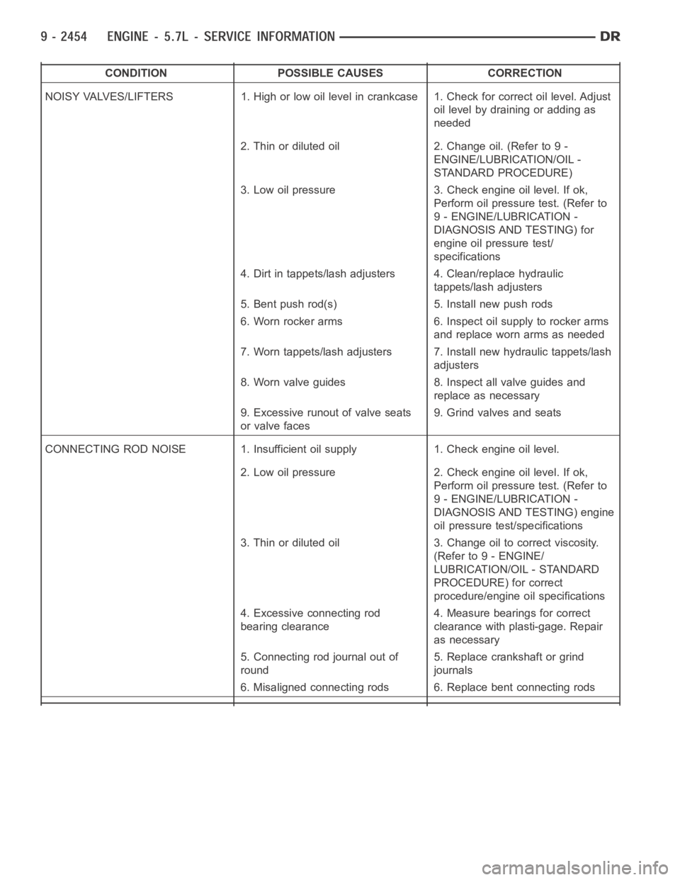
CONDITION POSSIBLE CAUSES CORRECTION
NOISY VALVES/LIFTERS 1. High or low oil level in crankcase 1. Check for correct oil level. Adjust
oil level by draining or adding as
needed
2. Thin or diluted oil 2. Change oil. (Refer to 9 -
ENGINE/LUBRICATION/OIL -
STANDARD PROCEDURE)
3. Low oil pressure 3. Check engine oil level. If ok,
Perform oil pressure test. (Refer to
9 - ENGINE/LUBRICATION -
DIAGNOSIS AND TESTING) for
engine oil pressure test/
specifications
4. Dirt in tappets/lash adjusters 4. Clean/replace hydraulic
tappets/lash adjusters
5. Bent push rod(s) 5. Install new push rods
6. Worn rocker arms 6. Inspect oil supply to rocker arms
and replace worn arms as needed
7. Worn tappets/lash adjusters 7. Install new hydraulic tappets/lash
adjusters
8. Worn valve guides 8. Inspect all valve guides and
replace as necessary
9. Excessive runout of valve seats
or valve faces9. Grind valves and seats
CONNECTING ROD NOISE 1. Insufficient oil supply 1. Check engine oil level.
2. Low oil pressure 2. Check engine oil level. If ok,
Perform oil pressure test. (Refer to
9 - ENGINE/LUBRICATION -
DIAGNOSIS AND TESTING) engine
oil pressure test/specifications
3. Thin or diluted oil 3. Change oil to correct viscosity.
(Refer to 9 - ENGINE/
LUBRICATION/OIL - STANDARD
PROCEDURE) for correct
procedure/engine oil specifications
4. Excessive connecting rod
bearing clearance4. Measure bearings for correct
clearance with plasti-gage. Repair
as necessary
5. Connecting rod journal out of
round5. Replace crankshaft or grind
journals
6. Misaligned connecting rods 6. Replace bent connecting rods
Page 1793 of 5267
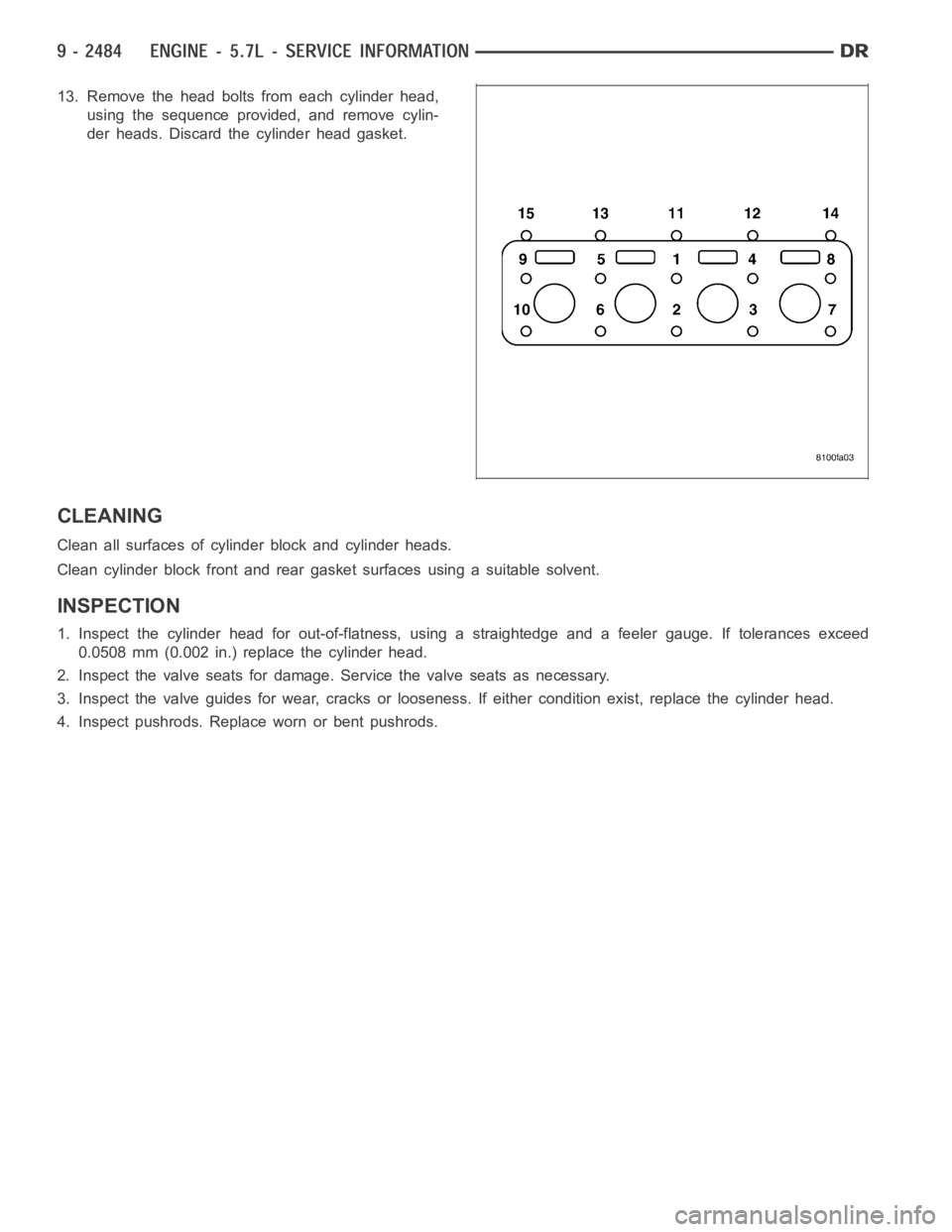
13. Remove the head bolts from each cylinder head,
using the sequence provided, and remove cylin-
der heads. Discard the cylinder head gasket.
CLEANING
Clean all surfaces of cylinder block and cylinder heads.
Clean cylinder block front and rear gasket surfaces using a suitable solvent.
INSPECTION
1. Inspect the cylinder head for out-of-flatness, using a straightedge and a feeler gauge. If tolerances exceed
0.0508 mm (0.002 in.) replace the cylinder head.
2. Inspect the valve seats for damage. Service the valve seats as necessary.
3. Inspect the valve guides for wear, cracks or looseness. If either condition exist, replace the cylinder head.
4. Inspect pushrods. Replace worn or bent pushrods.
Page 1805 of 5267
VALVES & SEATS - INTAKE/EXHAUST
DESCRIPTION
DESCRIPTION - VALVE GUIDES
The valve guides are made of powdered metal and are pressed into the cylinder head. The guides are not replace-
able or serviceable, and valve guide reaming is not recommended. If the guides are worn beyond acceptable limits,
replace the cylinder heads.
DESCRIPTION
Both the intake and exhaust valves are made of steel. The intake valve is 50.93 mm (2.00 inches) in diameter and
the exhaust valve is 39.53 mm (1.55 inches) in diameter. All valves use three bead lock keepers to retain the
springs and promote valve rotation.
STANDARD PROCEDURE - REFACING
NOTE: Valve seats that are worn or burned can be reworked, provided that correct angle and seat width are
maintained. Otherwise the cylinder head must be replaced.
NOTE: When refacing valves and valve seats, it is important that the correct size valve guide pilot be used
for reseating stones. A true and complete surface must be obtained.
1. Using a suitable dial indicator measure the center of the valve seat Total run out must not exceed 0.051 mm
(0.002 in).
2. Apply a small amount of Prussian blue to the valve seat, insert the valve into the cylinder head, while applying
light pressure on the valve rotate the valve. Remove the valve and examine the valve face. If the blue is trans-
ferred below the top edge of the valve face, lower the valve seat using a 15 degree stone. If the blue is trans-
ferred to the bottom edge of the valve face, raise the valve seat using a 65 degree stone.
3. When the seat is properly positioned the width of the intake seat must be 1.018 - 1.62 mm (0.0464 - 0.0637 in.)
and the exhaust seat must be 1.48 - 1.92 mm (0.058 - 0.075 in.).
4. Check the valve spring installed height after refacing the valve and seat.Theinstalledheightforbothintakeand
exhaust valve springs must not exceed 46.0 mm (1.81 in.).
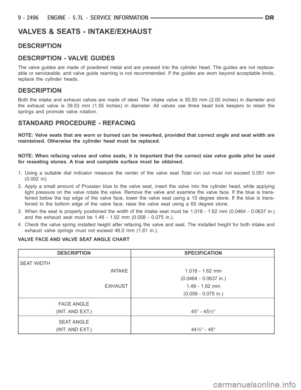
VALVE FACE AND VALVE SEAT ANGLE CHART
DESCRIPTION SPECIFICATION
SEAT WIDTH
INTAKE 1.018 - 1.62 mm
(0.0464 - 0.0637 in.)
EXHAUST 1.48 - 1.92 mm
(0.058 - 0.075 in.)
FA C E A N G L E
(INT. AND EXT.) 45° - 45
1⁄2°
SEAT ANGLE
(INT. AND EXT.) 44
1⁄2° - 45°
Page 1806 of 5267
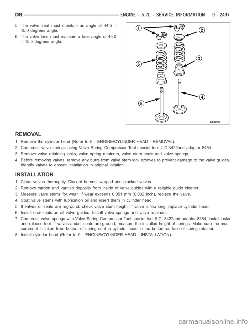
5. The valve seat must maintain an angle of 44.5 –
45.0 degrees angle.
6. Thevalvefacemustmaintainafaceangleof45.0
– 45.5 degrees angle.
REMOVAL
1. Remove the cylinder head (Refer to 9 - ENGINE/CYLINDER HEAD - REMOVAL).
2. Compress valve springs using Valve Spring Compressor Tool special tool# C-3422and adapter 8464.
3. Remove valve retaining locks, valve spring retainers, valve stem sealsand valve springs.
4. Before removing valves, remove any burrs from valve stem lock grooves toprevent damage to the valve guides.
Identify valves to ensure installation in original location.
INSTALLATION
1. Clean valves thoroughly. Discard burned, warped and cracked valves.
2. Remove carbon and varnish deposits from inside of valve guides with a reliable guide cleaner.
3. Measure valve stems for wear. If wear exceeds 0.051 mm (0.002 inch), replace the valve.
4. Coat valve stems with lubrication oil and insert them in cylinder head.
5. If valves or seats are reground, check valve stem height. If valve is too long, replace cylinder head.
6. Install new seals on all valve guides. Install valve springs and valve retainers.
7. Compress valve springs with Valve Spring Compressor Tool special tool #C- 3422and adapter 8464, install locks
and release tool. If valves and/or seats are ground, measure the installedheight of springs. Make sure the mea-
surement is taken from bottom of spring seat in cylinder head to the bottom surface of spring retainer.
8. Install cylinder head (Refer to 9 - ENGINE/CYLINDER HEAD - INSTALLATION).
Page 1849 of 5267
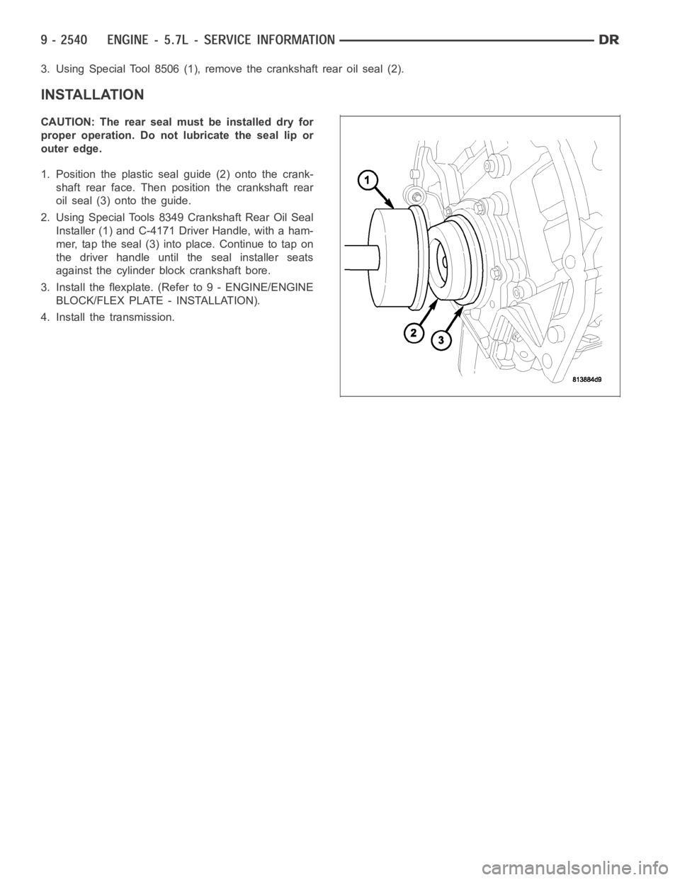
3. Using Special Tool 8506 (1), remove the crankshaft rear oil seal (2).
INSTALLATION
CAUTION: The rear seal must be installed dry for
proper operation. Do not lubricate the seal lip or
outer edge.
1. Position the plastic seal guide (2) onto the crank-
shaft rear face. Then position the crankshaft rear
oil seal (3) onto the guide.
2. Using Special Tools 8349 Crankshaft Rear Oil Seal
Installer (1) and C-4171 Driver Handle, with a ham-
mer, tap the seal (3) into place. Continue to tap on
the driver handle until the seal installer seats
against the cylinder block crankshaft bore.
3. Install the flexplate. (Refer to 9 - ENGINE/ENGINE
BLOCK/FLEX PLATE - INSTALLATION).
4. Install the transmission.
Page 1903 of 5267
page page
ENGINE - 5.9L DIESEL - SERVICE
INFORMATION
DESCRIPTION
DESCRIPTION - 5.9L DIESEL .............. 2596
DESCRIPTION - CRANKCASE BREATHER . . 2597
DIAGNOSIS AND TESTING
DIAGNOSIS AND TESTING - ENGINE
DIAGNOSIS - MECHANICAL............... 2597
DIAGNOSIS AND TESTING - SMOKE
DIAGNOSIS CHARTS..................... 2599
DIAGNOSIS AND TESTING - CYLINDER
COMPRESSION/LEAKAGE TESTS......... 2602
STANDARD PROCEDURE
STANDARD PROCEDURE - FORM-IN-
PLACE GASKETS AND SEALERS.......... 2603
STANDARD PROCEDURE - REPAIR
DAMAGED OR WORN THREADS.......... 2604
STANDARD PROCEDURE—HYDROSTATIC
LOCK.................................... 2604
REMOVAL - ENGINE ........................ 2605
INSTALLATION - ENGINE ................... 2610
SPECIFICATIONS
SPECIFICATIONS - 5.9L DIESEL ........... 2615
TORQUE ................................. 2617
SPECIAL TOOLS
5.9L DIESEL ENGINE ..................... 2619
ENGINE DATA PLATE
DESCRIPTION ............................. 2621
AIR CLEANER ELEMENT
REMOVAL ................................. 2622
INSTALLATION ............................. 2623
CYLINDER HEAD
DESCRIPTION ............................. 2624
REMOVAL ................................. 2624
CLEANING
CLEANING ............................... 2626
CLEANING—CROSSHEADS ............... 2626
CLEANING—PUSHRODS .................. 2626
INSPECTION
INSPECTION............................. 2627
INSPECTION - CROSSHEADS . . ........... 2627
INSPECTION—PUSHRODS................ 2628
INSTALLATION ............................. 2628
COVER - CYLINDER HEAD
REMOVAL
REMOVAL - ROCKER HOUSING ........... 2632
REMOVAL - CYL HEAD COVER ............ 2632
REMOVAL - CYL HEAD COVER GASKET . . . 2634
CLEANING
CLEANING CYLINDER HEAD COVER ...... 2634
INSPECTION - CYLINDER HEAD COVER ..... 2634INSTALLATION
INSTALLATION - ROCKER HOUSING ....... 2634
INSTALLATION - CYL HEAD COVER ....... 2635
INSTALLATION - CYL HEAD COVER
GASKET................................. 2636
VALVES & SEATS - INTAKE/EXHAUST
DESCRIPTION ............................. 2638
STANDARD PROCEDURE
STANDARD PROCEDURE - VALVES,
GUIDES AND SPRINGS................... 2638
STANDARD PROCEDURE - VALVE LASH
ADJUSTMENT AND VERIFICATION......... 2643
REMOVAL ................................. 2644
INSTALLATION ............................. 2646
ROCKER ARM
DESCRIPTION ............................. 2647
REMOVAL ................................. 2647
CLEANING ................................. 2648
INSPECTION............................... 2648
INSTALLATION ............................. 2649
ENGINE BLOCK
STANDARD PROCEDURE
STANDARD PROCEDURE - CYLINDER
BLOCK REFACING........................ 2651
STANDARD PROCEDURE - CYLINDER
BORE - DE-GLAZE........................ 2651
STANDARD PROCEDURE—CYLINDER
BORE REPAIR............................ 2652
STANDARD PROCEDURE - CAM BORE
REPAIR.................................. 2655
INSPECTION............................... 2655
CAMSHAFT & BEARINGS (IN BLOCK)
REMOVAL
CAMSHAFT BEARINGS................... 2657
CAMSHAFT .............................. 2657
INSPECTION
............................... 2659
INSTALLATION
CAMSHAFT BEARINGS................... 2661
CAMSHAFT .............................. 2661
BEARINGS - CONNECTING ROD
STANDARD PROCEDURE - CONNECTING
ROD BEARING AND CRANKSHAFT
JOURNAL CLEARANCE................... 2663
CRANKSHAFT & GEAR
DESCRIPTION ............................. 2664
REMOVAL - GEAR .......................... 2664
INSTALLATION - GEAR ..................... 2664
BEARINGS - CRANKSHAFT MAIN
STANDARD PROCEDURE - MAIN BEARING
CLEARANCE ............................. 2665
Page 1910 of 5267

EXCESSIVE WHITE SMOKE
POSSIBLE CAUSE CORRECTION
Fuel filter plugged. Refer to Powertrain Diagnostic Manual for fuel system
testing.
Fuel grade not correct or fuel quality is poor. Temporarily change fuel brands and note condition.
Change brand if necessary.
Fuel heater element or fuel heater temperature sensor
malfunctioning. This will cause wax type build-up in fuel
filter.Refer to Fuel Heater Testing (Refer to 14 - FUEL
SYSTEM/FUEL DELIVERY/FUEL HEATER -
DIAGNOSIS AND TESTING).
Fuel injector malfunctioning. A DTC should have been set. Perform “Cylinder
Performance Test
orCylinder cutout Testusing DRB
scan tool to isolate individual cylinders. Also refer to
Powertrain Diagnostic Procedures Information and,
(Refer to 14 - FUEL SYSTEM/FUEL INJECTION/FUEL
INJECTOR - DIAGNOSIS AND TESTING).
Fuel injector hold-downs loose. Torque to specifications.
Fuel injector protrusion not correct. Check washer (shim) at bottom of fuel injector for
correct thickness. (Referto 14 - FUEL SYSTEM/FUEL
INJECTION/FUEL INJECTOR - INSTALLATION)
Fuel injection pump malfunctioning. A DTC should have been set. Refer to Powertrain
Diagnostic Procedures Information.
Fuel supply side restriction. Refer to Powertrain Diagnostic Manual for fuel system
testing.
Fuel transfer (lift) pump malfunctioning. A DTC may have been set. Refer toPowertrain
Diagnostic Procedures Information.
Intake/Exhaust valve adjustments not correct (too tight). (Refer to 9 - ENGINE/CYLINDER HEAD/INTAKE/
EXHAUST VALVES & SEATS - STANDARD
PROCEDURE).
Intake manifold air temperature sensor malfunctioning. A DTC should havebeen set. Refer to Powertrain
Diagnostic Procedures Information.
Intake manifold heater circuit not functioning correctly in
cold weather.A DTC should have been set. Refer to Powertrain
Diagnostic Procedures Information. Also check heater
elements for correct operation.
Intake manifold heater elements not functioning
correctly in cold weather.A DTC should have been set if heater elements are
malfunctioning. Refer to Powertrain Diagnostic
Procedures Information.
Internal engine damage (scuffed cylinder). Analyze engine oil and inspect oil filter to locate area of
probable damage.
Restriction in fuel supply side of fuel system. Refer to Powertrain Diagnostic Manual for fuel system
testing.
EXCESSIVE BLUE SMOKE
POSSIBLE CAUSE CORRECTION
Dirty air cleaner or restricted turbocharger intake duct. Check Filter Minder
at air filter housing. (Refer to 9 -
ENGINE/AIR INTAKE SYSTEM/AIR CLEANER
ELEMENT - REMOVAL).
Air leak in boost system between turbocharger
compressor outlet and intake manifold.Service air charge system..
Obstruction in exhaust manifold. Remove exhaust manifold and inspect forblockage
(Refer to 9 - ENGINE/MANIFOLDS/EXHAUST
MANIFOLD - REMOVAL).
Page 1911 of 5267
EXCESSIVE BLUE SMOKE
POSSIBLE CAUSE CORRECTION
Restricted turbocharger drain tube. Remove turbocharger drain tube and remove
obstruction.
Crankcase ventilation system plugged. Inspect crankcase ventilation system for function
Valve seals are worn, brittle, or improperly installed. Replace valve stemoilseals(Referto9-ENGINE/
CYLINDER HEAD/INTAKE/EXHAUST VALVES &
SEATS - REMOVAL).
Valve stems and/or guides are worn. Remove valves and inspect valves and guides. (Refer
to 9 - ENGINE/CYLINDER HEAD/INTAKE/EXHAUST
VALVES & SEATS - STANDARD PROCEDURE).
Broken or Improperly installed piston rings. Tear down engine and inspectpiston rings.
Excessive piston ring end gap. Remove pistons and measure piston ring end gap
(Refer to 9 - ENGINE/ENGINE BLOCK/PISTON RINGS
- STANDARD PROCEDURE).
Excessive cylinder bore wear and taper. Remove pistons and measure cylinder bore wear and
taper (Refer to 9 - ENGINE/ENGINE BLOCK -
STANDARD PROCEDURE).
Cylinder damage. Remove pistons and inspect cylinder bore for cracks or
porosity. Repair with cylinder liner if necessary. (Refer
to 9 - ENGINE/ENGINE BLOCK - STANDARD
PROCEDURE).
Piston damage. Remove pistons and inspect for cracks, holes. Measure
piston for out-of-round and taper (Refer to 9 -
ENGINE/ENGINE BLOCK/PISTON & CONNECTING
ROD - INSPECTION).
Turbocharger failure. (Refer to 11 - EXHAUST SYSTEM/TURBOCHARGER
SYSTEM/TURBOCHARGER - INSPECTION).
DIAGNOSIS AND TESTING - CYLINDER COMPRESSION/LEAKAGE TESTS
CYLINDER COMPRESSION PRESSURE
The results of a cylinder compressionpressure test can be utilized to diagnose several engine malfunctions.
Ensure batteries are completely charged and the engine starter motor is ingood operating condition. Otherwise, the
indicated compression pressures may not be valid for diagnostic purposes.
1. Disconnect the fuel inlet line to the fuel filter housing. Plug the fuel line from the fuel tank.
NOTE: Failure to plug fuel line will result in fuel leak.
2. Remove fuel transfer pump relay from PDC.
3. Start the engine and idle until the engine stalls (runs out of fuel).
4. Remove the cylinder head cover. (Refer to 9 - ENGINE/CYLINDER HEAD/CYLINDER HEAD COVER(S) -
REMOVAL)
5. Remove the cylinder head cover carrier gasket. (Refer to 9 - ENGINE/CYLINDER HEAD/CYLINDER HEAD
COVER(S) - REMOVAL)
6. Remove the high pressure fuel line between the cylinder head and fuel rail for the cylinder to be tested. Use
tool# 9011 to cap this fuel rail on the cylinder being tested.
7. Remove the fuel connector tube nut and fuel connector tube.
8. Remove the exhaust rocker lever.
9. Use Tool 9010 to remove the injector and copper sealing washer.
10. Install the exhaust rocker lever and torque to 36 Nꞏm (27 ft. lbs.).
11. Cover the remaining rocker levers with clean shop towels to prevent anyoil splatter under the hood.