2006 DODGE RAM SRT-10 seats
[x] Cancel search: seatsPage 1938 of 5267
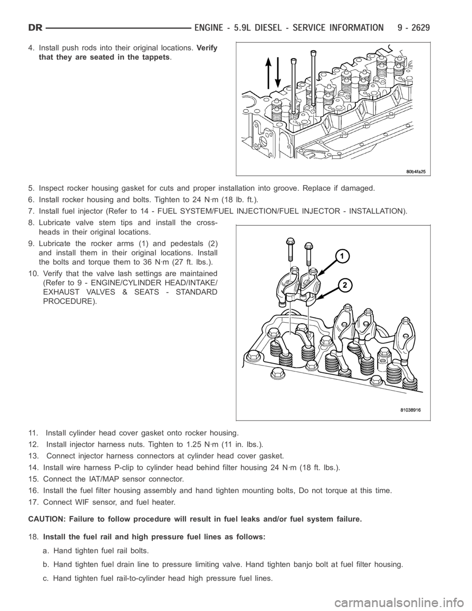
4. Install push rods into their original locations.Ve r i f y
that they are seated in the tappets.
5. Inspect rocker housing gasket for cuts and proper installation into groove. Replace if damaged.
6. Install rocker housing and bolts. Tighten to 24 Nꞏm (18 lb. ft.).
7. Install fuel injector (Refer to 14 - FUEL SYSTEM/FUEL INJECTION/FUEL INJECTOR - INSTALLATION).
8. Lubricate valve stem tips and install the cross-
heads in their original locations.
9. Lubricate the rocker arms (1) and pedestals (2)
and install them in their original locations. Install
the bolts and torque them to 36 Nꞏm (27 ft. lbs.).
10. Verify that the valve lash settings are maintained
(Refer to 9 - ENGINE/CYLINDER HEAD/INTAKE/
EXHAUST VALVES & SEATS - STANDARD
PROCEDURE).
11. Install cylinder head cover gasket onto rocker housing.
12. Install injector harness nuts. Tighten to 1.25 Nꞏm (11 in. lbs.).
13. Connect injector harness connectors at cylinder head cover gasket.
14. Install wire harness P-clip to cylinder head behind filter housing 24 Nꞏm (18 ft. lbs.).
15. Connect the IAT/MAP sensor connector.
16. Install the fuel filter housing assembly and hand tighten mounting bolts, Do not torque at this time.
17. Connect WIF sensor, and fuel heater.
CAUTION: Failure to follow procedure will result in fuel leaks and/or fuelsystem failure.
18.Install the fuel rail and high pressure fuel lines as follows:
a. Hand tighten fuel rail bolts.
b. Hand tighten fuel drain line to pressure limiting valve. Hand tighten banjo bolt at fuel filter housing.
c. Hand tighten fuel rail-to-cylinder head high pressure fuel lines.
Page 1947 of 5267
VALVES & SEATS - INTAKE/EXHAUST
DESCRIPTION
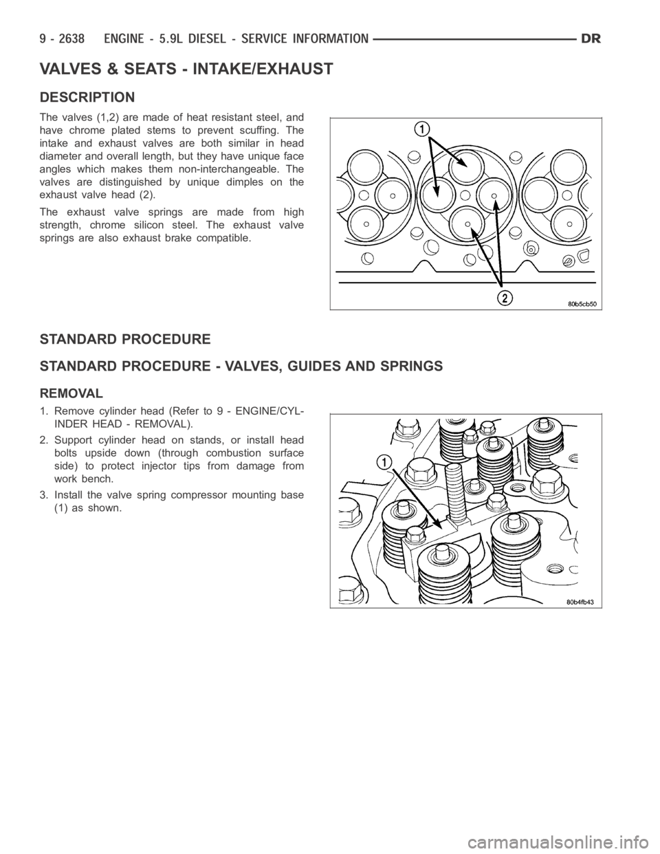
The valves (1,2) are made of heat resistant steel, and
have chrome plated stems to prevent scuffing. The
intake and exhaust valves are both similar in head
diameter and overall length, but they have unique face
angles which makes them non-interchangeable. The
valves are distinguished by unique dimples on the
exhaust valve head (2).
The exhaust valve springs are made from high
strength, chrome silicon steel. The exhaust valve
springs are also exhaust brake compatible.
STANDARD PROCEDURE
STANDARD PROCEDURE - VALVES, GUIDES AND SPRINGS
REMOVAL
1. Remove cylinder head (Refer to 9 - ENGINE/CYL-
INDER HEAD - REMOVAL).
2. Support cylinder head on stands, or install head
bolts upside down (through combustion surface
side) to protect injector tips from damage from
work bench.
3. Install the valve spring compressor mounting base
(1) as shown.
Page 1955 of 5267
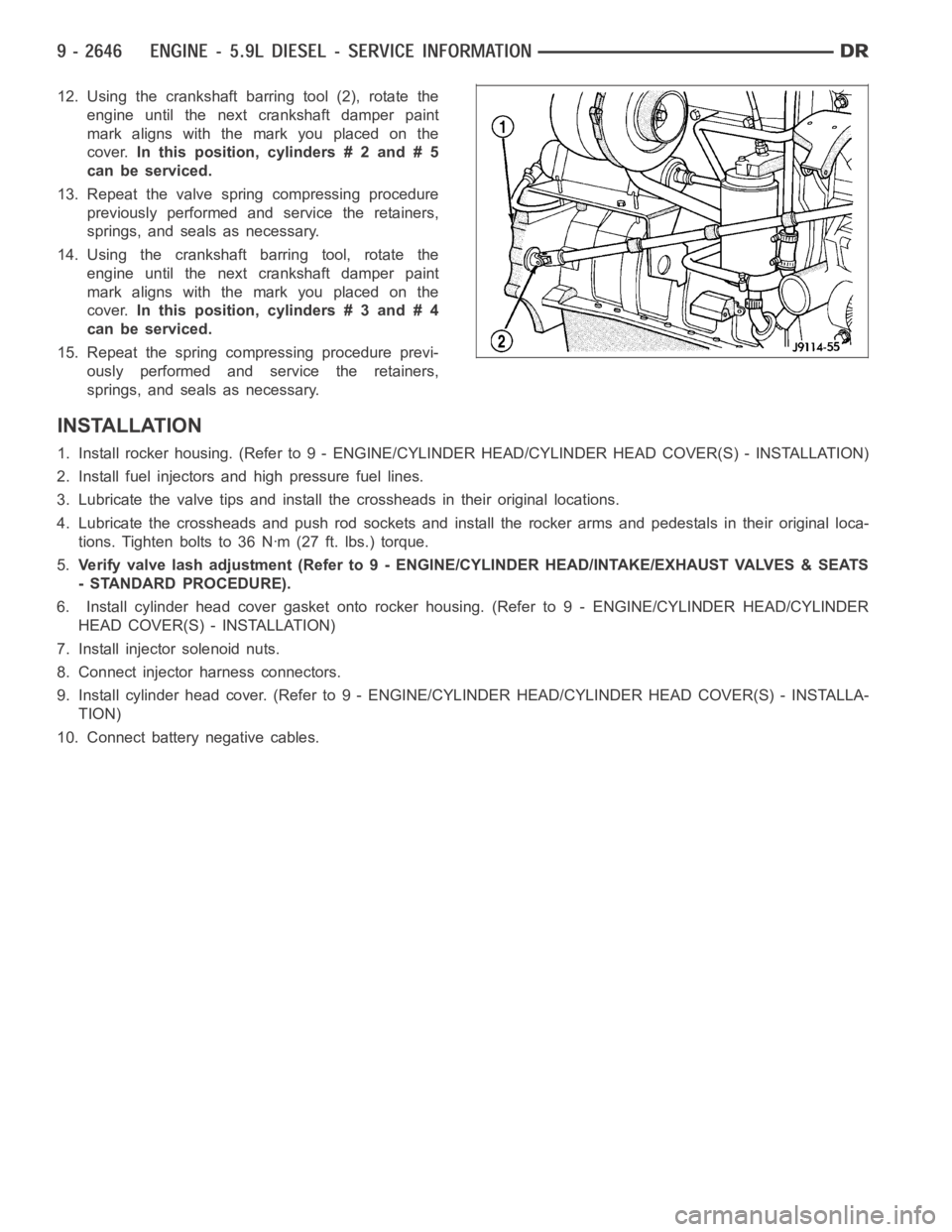
12. Using the crankshaft barring tool (2), rotate the
engine until the next crankshaft damper paint
mark aligns with the mark you placed on the
cover.In this position, cylinders # 2 and # 5
can be serviced.
13. Repeat the valve spring compressing procedure
previously performed and service the retainers,
springs, and seals as necessary.
14. Using the crankshaft barring tool, rotate the
engine until the next crankshaft damper paint
mark aligns with the mark you placed on the
cover.In this position, cylinders # 3 and # 4
can be serviced.
15. Repeat the spring compressing procedure previ-
ously performed and service the retainers,
springs, and seals as necessary.
INSTALLATION
1. Install rocker housing. (Refer to 9 -ENGINE/CYLINDER HEAD/CYLINDER HEAD COVER(S) - INSTALLATION)
2. Install fuel injectors and high pressure fuel lines.
3. Lubricate the valve tips and install the crossheads in their original locations.
4. Lubricate the crossheads and push rod sockets and install the rocker arms and pedestals in their original loca-
tions. Tighten bolts to 36 Nꞏm (27 ft. lbs.) torque.
5.Verify valve lash adjustment (Refer to 9 - ENGINE/CYLINDER HEAD/INTAKE/EXHAUST VALVES & SEATS
- STANDARD PROCEDURE).
6. Install cylinder head cover gasket onto rocker housing. (Refer to 9 - ENGINE/CYLINDER HEAD/CYLINDER
HEAD COVER(S) - INSTALLATION)
7. Install injector solenoid nuts.
8. Connect injector harness connectors.
9. Install cylinder head cover. (Refer to 9 - ENGINE/CYLINDER HEAD/CYLINDER HEAD COVER(S) - INSTALLA-
TION)
10. Connect battery negative cables.
Page 1958 of 5267
Push Rods
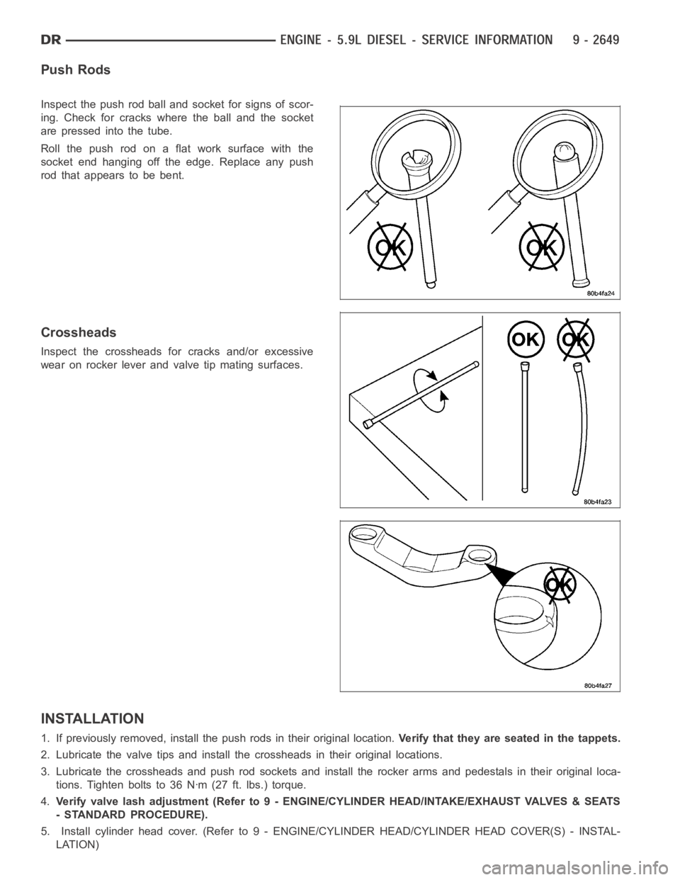
Inspect the push rod ball and socket for signs of scor-
ing. Check for cracks where the ball and the socket
are pressed into the tube.
Roll the push rod on a flat work surface with the
socket end hanging off the edge. Replace any push
rod that appears to be bent.
Crossheads
Inspect the crossheads for cracks and/or excessive
wear on rocker lever and valve tip mating surfaces.
INSTALLATION
1. If previously removed, install the push rods in their original location.Verify that they are seated in the tappets.
2. Lubricate the valve tips and install the crossheads in their original locations.
3. Lubricate the crossheads and push rod sockets and install the rocker arms and pedestals in their original loca-
tions. Tighten bolts to 36 Nꞏm (27 ft. lbs.) torque.
4.Verify valve lash adjustment (Refer to 9 - ENGINE/CYLINDER HEAD/INTAKE/EXHAUST VALVES & SEATS
- STANDARD PROCEDURE).
5. Install cylinder head cover. (Refer to 9 - ENGINE/CYLINDER HEAD/CYLINDER HEAD COVER(S) - INSTAL-
LATION)
Page 1970 of 5267
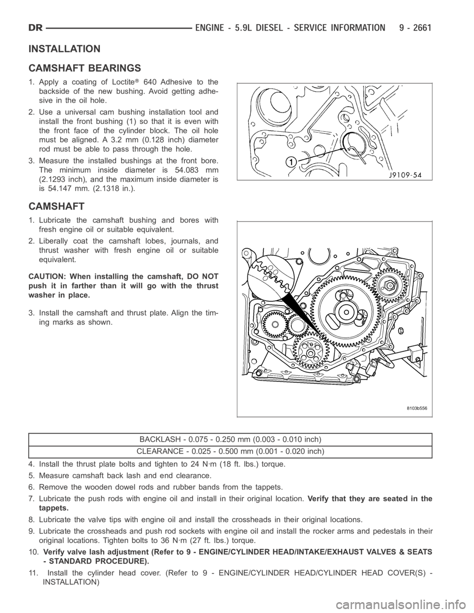
INSTALLATION
CAMSHAFT BEARINGS
1. Apply a coating of Loctite640 Adhesive to the
backside of the new bushing. Avoid getting adhe-
sive in the oil hole.
2. Use a universal cam bushing installation tool and
install the front bushing (1) so that it is even with
the front face of the cylinder block. The oil hole
must be aligned. A 3.2 mm (0.128 inch) diameter
rod must be able to pass through the hole.
3. Measure the installed bushings at the front bore.
The minimum inside diameter is 54.083 mm
(2.1293 inch), and the maximum inside diameter is
is 54.147 mm. (2.1318 in.).
CAMSHAFT
1. Lubricate the camshaft bushing and bores with
fresh engine oil or suitable equivalent.
2. Liberally coat the camshaft lobes, journals, and
thrust washer with fresh engine oil or suitable
equivalent.
CAUTION: When installing the camshaft, DO NOT
push it in farther than it will go with the thrust
washer in place.
3. Install the camshaft and thrust plate. Align the tim-
ing marks as shown.
BACKLASH - 0.075 - 0.250 mm (0.003 - 0.010 inch)
CLEARANCE - 0.025 - 0.500 mm (0.001 - 0.020 inch)
4. Install the thrust plate bolts and tighten to 24 Nꞏm (18 ft. lbs.) torque.
5. Measure camshaft back lash and end clearance.
6. Remove the wooden dowel rods and rubber bands from the tappets.
7. Lubricate the push rods with engine oil and install in their original location.Verify that they are seated in the
tappets.
8. Lubricate the valve tips with engine oil and install the crossheads in their original locations.
9. Lubricate the crossheads and push rod sockets with engine oil and install the rocker arms and pedestals in their
original locations. Tighten bolts to 36 Nꞏm (27 ft. lbs.) torque.
10.Verify valve lash adjustment (Refer to 9 - ENGINE/CYLINDER HEAD/INTAKE/EXHAUST VALVES & SEATS
- STANDARD PROCEDURE).
11. Install the cylinder head cover. (Refer to 9 - ENGINE/CYLINDER HEAD/CYLINDER HEAD COVER(S) -
INSTALLATION)
Page 2010 of 5267
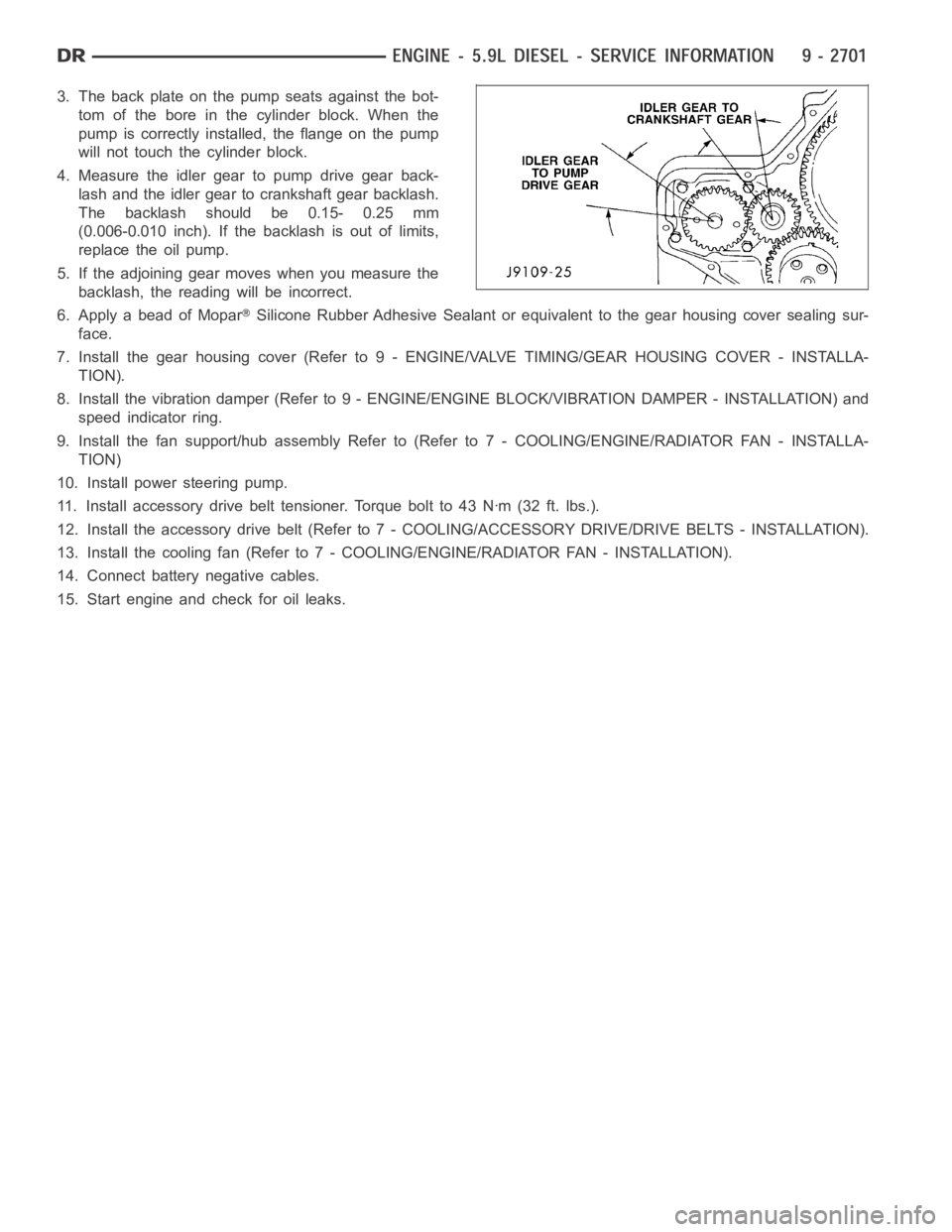
3. The back plate on the pump seats against the bot-
tom of the bore in the cylinder block. When the
pump is correctly installed, the flange on the pump
will not touch the cylinder block.
4. Measure the idler gear to pump drive gear back-
lash and the idler gear to crankshaft gear backlash.
The backlash should be 0.15- 0.25 mm
(0.006-0.010 inch). If the backlash is out of limits,
replace the oil pump.
5. If the adjoining gear moves when you measure the
backlash, the reading will be incorrect.
6. Apply a bead of Mopar
Silicone Rubber Adhesive Sealant or equivalent to the gear housing cover sealing sur-
face.
7. Install the gear housing cover (Refer to 9 - ENGINE/VALVE TIMING/GEAR HOUSING COVER - INSTALLA-
TION).
8. Install the vibration damper (Refer to 9 - ENGINE/ENGINE BLOCK/VIBRATION DAMPER - INSTALLATION) and
speed indicator ring.
9. Install the fan support/hub assemblyRefer to (Refer to 7 - COOLING/ENGINE/RADIATOR FAN - INSTALLA-
TION)
10. Install power steering pump.
11. Install accessory drive belt tensioner. Torque bolt to 43 Nꞏm (32 ft. lbs.).
12. Install the accessory drive belt (Refer to 7 - COOLING/ACCESSORY DRIVE/DRIVE BELTS - INSTALLATION).
13. Install the cooling fan (Refer to 7 - COOLING/ENGINE/RADIATOR FAN - INSTALLATION).
14. Connect battery negative cables.
15. Start engine and check for oil leaks.
Page 2020 of 5267
page page
ENGINE - 8.3L - SERVICE INFORMATION
DESCRIPTION ............................. 2713
DIAGNOSIS AND TESTING
INTRODUCTION . ......................... 2714
ENGINE DIAGNOSIS - PERFORMANCE .... 2715
ENGINE DIAGNOSIS - MECHANICAL ....... 2716
CYLINDER COMPRESSION PRESSURE
TEST.................................... 2718
CYLINDER COMBUSTION PRESSURE
LEAKAGE TEST.......................... 2718
CYLINDER HEAD GASKET FAILURE
DIAGNOSIS.............................. 2719
HYDRAULIC TAPPET NOISE DIAGNOSIS . . . 2720
ENGINE OIL LEAK INSPECTION ........... 2720
STANDARD PROCEDURE
ENGINE CORE AND OIL GALLERY PLUGS . 2722
FORM-IN-PLACE GASKETS AND SEALERS . 2722
ENGINE GASKET SURFACE
PREPARATION........................... 2723
HYDROSTATIC LOCKED ENGINE .......... 2723
REMOVAL - ENGINE ASSEMBLY . . ........... 2724
INSTALLATION - ENGINE ASSEMBLY ........ 2728
SPECIFICATIONS
ENGINE ................................. 2731
TORQUE ................................. 2736
SPECIAL TOOLS
ENGINE ................................. 2738
SYSTEM-AIR INTAKE
DESCRIPTION ............................. 2741
ELEMENT-AIR CLEANER
REMOVAL ................................. 2742
INSTALLATION ............................. 2743
HOUSING-AIR CLEANER
REMOVAL ................................. 2744
INSTALLATION ............................. 2745
MOUNTS-ENGINE
REMOVAL ................................. 2746
INSTALLATION ............................. 2747
MANIFOLD-INTAKE
DIAGNOSIS AND TESTING
INTAKE MANIFOLD LEAKS ................ 2748
REMOVAL ................................. 2748
INSPECTION ............................... 2750
INSTALLATION ............................. 2751
MANIFOLD-EXHAUST
REMOVAL ................................. 2754
INSPECTION ............................... 2755
INSTALLATION ............................. 2755
HEAD(S)-CYLINDER
REMOVAL - CYLINDER HEAD(S) ............. 2757CLEANING
CLEANING AND INSPECTION............. 2758
INSTALLATION - CYLINDER HEAD(S) ........ 2758
COVER(S)-CYLINDER HEAD
REMOVAL ................................. 2760
INSTALLATION ............................. 2761
ARMS-ROCKER
REMOVAL ................................. 2762
INSTALLATION ............................. 2762
SPRINGS/SEALS-VALVE
DIAGNOSIS AND TESTING
VALVE SPRING TESTING ................. 2763
STANDARD PROCEDURE - VALVE SPRING/
SEAL SERVICE IN-CAR ................... 2763
REMOVAL ................................. 2764
INSTALLATION ............................. 2765
INTAKE/EXHAUST - VALVES/SEATS/GUIDES
STANDARD PROCEDURE - VALVE AND
VALVE SEAT - REFACING ................. 2766
INSPECTION............................... 2767
COVER-TIMING CHAIN
REMOVAL ................................. 2769
INSTALLATION ............................. 2771
TIMING CHAIN AND SPROCKETS
REMOVAL ................................. 2774
INSTALLATION ............................. 2775
LUBRICATION
DESCRIPTION ............................. 2777
OPERATION ............................... 2777
DIAGNOSIS AND TESTING
CHECKING ENGINE OIL PRESSURE ....... 2777
ENGINE OIL LEAK ........................ 2777
OIL
STANDARD PROCEDURE
CHECKING ENGINE OIL LEVEL........... 2779
ENGINE OILAND FILTER CHANGE ........ 2779
COOLER & LINES-OIL
DESCRIPTION ............................. 2781
OPERATION ............................... 2781
STANDARD PROCEDURE - OIL COOLER LINE
QUICK CONNECT FITTING DISASSEMBLY/
ASSEMBLY............................... 2781
REMOVAL ................................. 2782
INSTALLATION ............................. 2783
PAN-OIL
REMOVAL ................................. 2784
INSTALLATION ............................. 2785
PUMP-OIL
REMOVAL ................................. 2788
DISASSEMBLY . ............................ 2788
CLEANING ................................. 2789
Page 2025 of 5267
CONDITION POSSIBLE CAUSES CORRECTION
ENGINE STALLS OR
ROUGH IDLE1. Carbon buildup on throttle plate. 1. Remove throttle body and de-carbon.
2. Engine idle speed too low. 2. Check Idle Air Control circuit. Refer to
the appropriate Diagnostic Information for
IAC motor testing.
3. Worn or incorrectly gapped spark
plugs.3. Replace spark plugs or set gap.
4. Faulty or crossed ignition cables. 4. Check for correct firing order or replace
ignition cables as necessary.
5. Faulty coil(s). 5. Test and replace as necessary.
6. Intake manifold vacuum leak. 6. Inspect intake manifold gasket and
vacuum hoses. Replace as necessary.
ENGINE MISSES ON
ACCELERATION1. Worn or incorrectly gapped spark
plugs.1. Replace spark plugs or set gap.
2. Faulty ignition cables. 2. Replace ignition cables as necessary.
3. Dirt or water in fuel system. 3. Clean system and replace fuel filter.
4. Burned, warped, or pitted valves. 4. Install new or reface valves as
necessary.
5. Faulty coil(s). 5. Test and replace as necessary.
ENGINE DIAGNOSIS - MECHANICAL
CONDITION POSSIBLE CAUSES CORRECTION
NOISY VALVES 1. High or low oil level incrankcase. 1. Check for correct oil level. Adjust oil level
by draining or adding as needed.
2. Thin or diluted oil. 2. Change oil and filter.
3. Low oil pressure. 3. Check engine oil level. If OK, perform oil
pressure test. (Refer to 9 - ENGINE/
LUBRICATION - DIAGNOSIS AND
TESTING).
4. Dirt in tappets/lash adjusters. 4. Clean/replace hydraulic tappets/lash
adjusters.
5. Bent push rod(s). 5. Replace push rod(s) as necessary.
6. Worn rocker arms. 6. Replace worn rocker arms and inspect
oil supply to rocker arms.
7. Worn tappets/lash adjusters. 7. Replace hydraulic tappets/hydrauliclash
adjusters.
8. Worn valve guides. 8. Ream and install new valves with
oversize stems.
9. Excessive runout of valve seats
on valve faces.9. Grind valve seats and valves.