Page 2074 of 5267
INSTALLATION
NOTE: Before replacing parts, inspect all related
valvetrain components for damage to prevent
engine misfire.
NOTE: Black valve seals are intake. Brown valve
seals are exhaust.
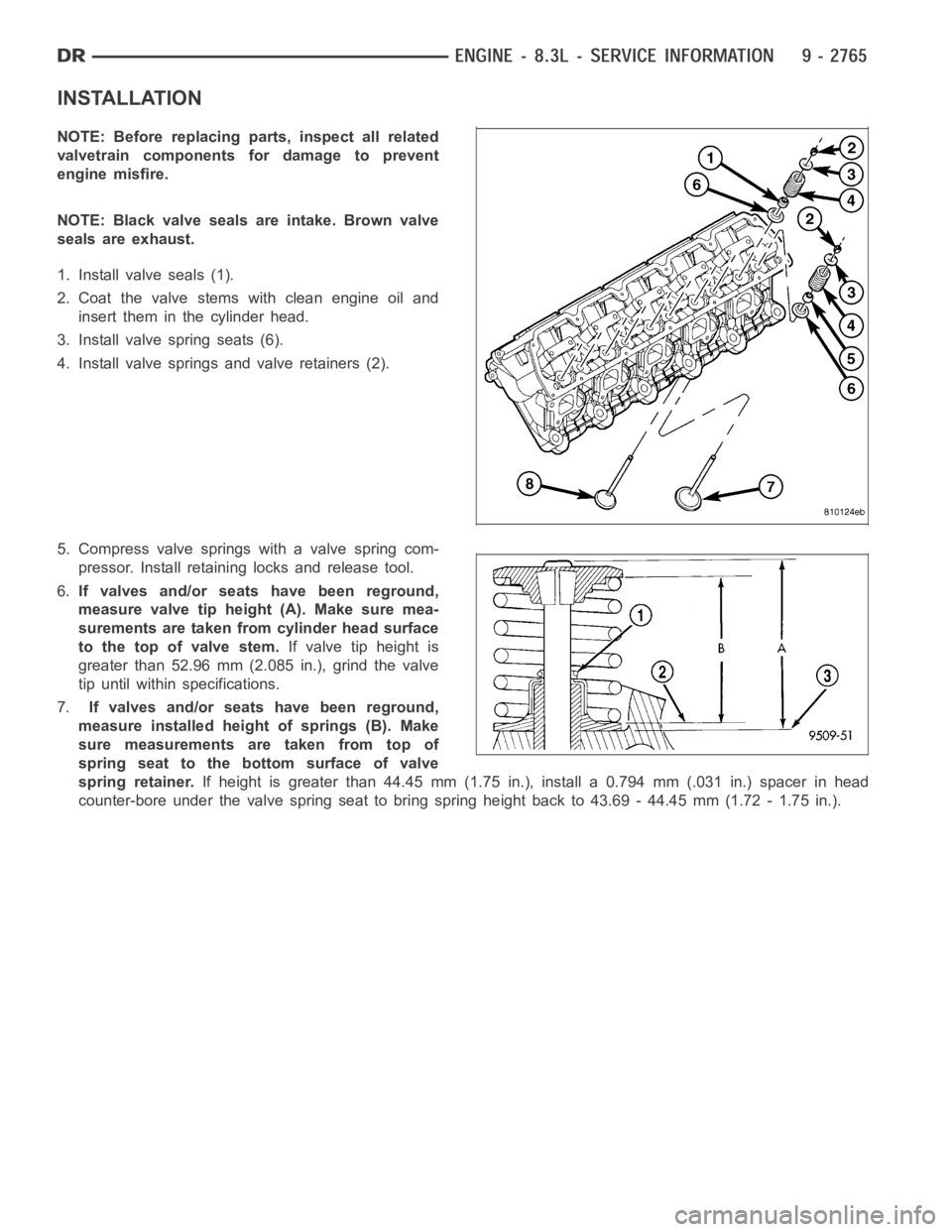
1. Install valve seals (1).
2. Coat the valve stems with clean engine oil and
insert them in the cylinder head.
3. Install valve spring seats (6).
4. Install valve springs and valve retainers (2).
5. Compress valve springs with a valve spring com-
pressor. Install retaining locks and release tool.
6.If valves and/or seats have been reground,
measure valve tip height (A). Make sure mea-
surements are taken from cylinder head surface
to the top of valve stem.If valve tip height is
greater than 52.96 mm (2.085 in.), grind the valve
tip until within specifications.
7.If valves and/or seats have been reground,
measure installed height of springs (B). Make
sure measurements are taken from top of
spring seat to the bottom surface of valve
spring retainer.If height is greater than 44.45 mm (1.75 in.), install a 0.794 mm (.031 in.) spacer in head
counter-bore under the valve spring seat to bring spring height back to 43.69 - 44.45 mm (1.72 - 1.75 in.).
Page 2075 of 5267
INTAKE/EXHAUST - VALVES/SEATS/GUIDES
STANDARD PROCEDURE - VALVE AND VALVE SEAT - REFACING
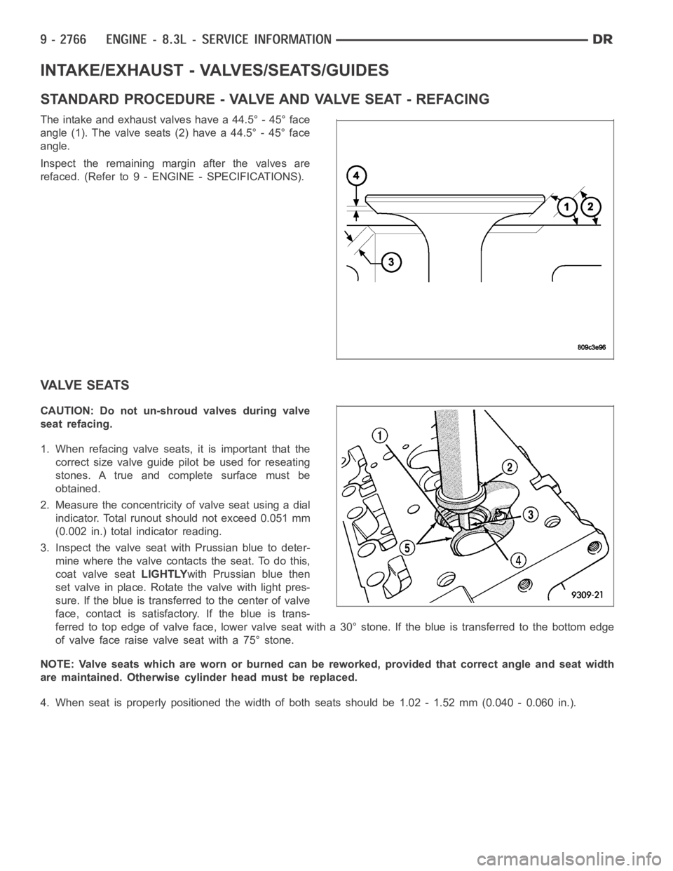
The intake and exhaust valves have a 44.5° - 45° face
angle (1). The valve seats (2) have a 44.5° - 45° face
angle.
Inspect the remaining margin after the valves are
refaced. (Refer to 9 - ENGINE - SPECIFICATIONS).
VALVE SEATS
CAUTION: Do not un-shroud valves during valve
seat refacing.
1. When refacing valve seats, it is important that the
correct size valve guide pilot be used for reseating
stones. A true and complete surface must be
obtained.
2. Measure the concentricity of valve seat using a dial
indicator. Total runout should not exceed 0.051 mm
(0.002 in.) total indicator reading.
3. Inspect the valve seat with Prussian blue to deter-
mine where the valve contacts the seat. To do this,
coat valve seatLIGHTLYwith Prussian blue then
set valve in place. Rotate the valve with light pres-
sure. If the blue is transferred to the center of valve
face, contact is satisfactory. If the blue is trans-
ferred to top edge of valve face, lower valve seat with a 30° stone. If the blue is transferred to the bottom edge
of valve face raise valve seat with a 75° stone.
NOTE: Valve seats which are worn or burned can be reworked, provided that correct angle and seat width
are maintained. Otherwise cylinder head must be replaced.
4. When seat is properly positioned the width of both seats should be 1.02 - 1.52 mm (0.040 - 0.060 in.).
Page 2076 of 5267
INSPECTION
Va l v e
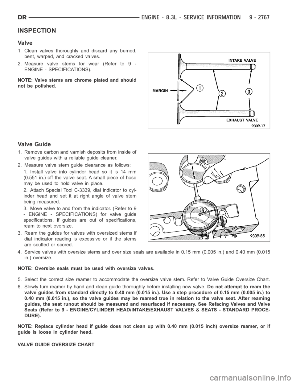
1. Clean valves thoroughly and discard any burned,
bent, warped, and cracked valves.
2. Measure valve stems for wear (Refer to 9 -
ENGINE - SPECIFICATIONS).
NOTE: Valve stems are chrome plated and should
not be polished.
Valve Guide
1. Remove carbon and varnish deposits from inside of
valve guides with a reliable guide cleaner.
2. Measure valve stem guide clearance as follows:
1. Install valve into cylinder head so it is 14 mm
(0.551 in.) off the valve seat. A small piece of hose
maybeusedtoholdvalveinplace.
2. Attach Special Tool C-3339, dial indicator to cyl-
inder head and set it at right angle of valve stem
being measured.
3. Move valve to and from the indicator. (Refer to 9
- ENGINE - SPECIFICATIONS) for valve guide
specifications. If guides are out of specifications,
ream to next oversize.
3. Ream the guides for valves with oversized stems if
dial indicator reading is excessive or if the stems
are scuffed or scored.
4. Service valves with oversize stems and over size seals are available in 0.15 mm (0.005 in.) and 0.40 mm (0.015
in.) oversize.
NOTE: Oversize seals must be used with oversize valves.
5. Select the correct size reamer to accommodate the oversize valve stem. Refer to Valve Guide Oversize Chart.
6. Slowly turn reamer by hand and clean guide thoroughly before installingnew valve.Do not attempt to ream the
valve guides from standard directly to 0.40 mm (0.015 in.). Use a step procedure of 0.15 mm (0.005 in.) to
0.40 mm (0.015 in.), so the valve guides may be reamed true in relation to thevalve seat. After reaming
guides, the seat runout should be measured and resurfaced if necessary. See Refacing Valves and Valve
Seats (Refer to 9 - ENGINE/CYLINDER HEAD/INTAKE/EXHAUST VALVES & SEATS - STANDARD PROCE-
DURE).
NOTE: Replace cylinder head if guide does not clean up with 0.40 mm (0.015 inch) oversize reamer, or if
guide is loose in cylinder head.
VALVE GUIDE OVERSIZE CHART
Page 2147 of 5267
8.3L ENGINE
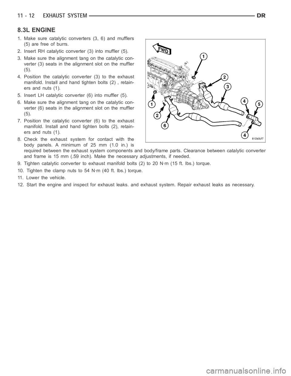
1. Make sure catalytic converters (3, 6) and mufflers
(5) are free of burrs.
2. Insert RH catalytic converter (3) into muffler (5).
3. Make sure the alignment tang on the catalytic con-
verter (3) seats in the alignment slot on the muffler
(5).
4. Position the catalytic converter (3) to the exhaust
manifold. Install and hand tighten bolts (2) , retain-
ers and nuts (1).
5. Insert LH catalytic converter (6) into muffler (5).
6. Make sure the alignment tang on the catalytic con-
verter (6) seats in the alignment slot on the muffler
(5).
7. Position the catalytic converter (6) to the exhaust
manifold. Install and hand tighten bolts (2), retain-
ers and nuts (1).
8. Check the exhaust system for contact with the
body panels. A minimum of 25 mm (1.0 in.) is
required between the exhaust system components and body/frame parts. Clearance between catalytic converter
and frame is 15 mm (.59 inch). Make the necessary adjustments, if needed.
9. Tighten catalytic converter to exhaust manifold bolts (2) to 20 Nꞏm (15 ft. lbs.) torque.
10. Tighten the clamp nuts to 54 Nꞏm (40 ft. lbs.) torque.
11. Lower the vehicle.
12. Start the engine and inspect for exhaust leaks. and exhaust system. Repair exhaust leaks as necessary.
Page 2458 of 5267
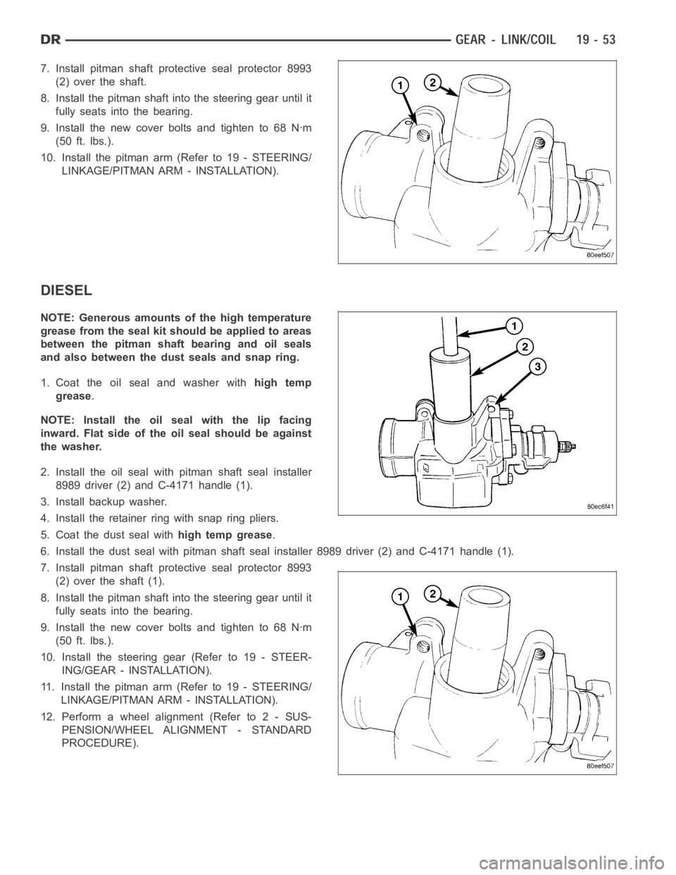
7. Install pitman shaft protective seal protector 8993
(2)overtheshaft.
8. Install the pitman shaft into the steering gear until it
fully seats into the bearing.
9. Install the new cover bolts and tighten to 68 Nꞏm
(50 ft. lbs.).
10. Install the pitman arm (Refer to 19 - STEERING/
LINKAGE/PITMAN ARM - INSTALLATION).
DIESEL
NOTE: Generous amounts of the high temperature
grease from the seal kit should be applied to areas
between the pitman shaft bearing and oil seals
and also between the dust seals and snap ring.
1. Coat the oil seal and washer withhigh temp
grease.
NOTE: Install the oil seal with the lip facing
inward. Flat side of the oil seal should be against
the washer.
2. Install the oil seal with pitman shaft seal installer
8989 driver (2) and C-4171 handle (1).
3. Install backup washer.
4. Install the retainer ring with snap ring pliers.
5. Coat the dust seal withhigh temp grease.
6. Install the dust seal with pitman shaft seal installer 8989 driver (2) andC-4171handle(1).
7. Install pitman shaft protective seal protector 8993
(2)overtheshaft(1).
8. Install the pitman shaft into the steering gear until it
fully seats into the bearing.
9. Install the new cover bolts and tighten to 68 Nꞏm
(50 ft. lbs.).
10. Install the steering gear (Refer to 19 - STEER-
ING/GEAR - INSTALLATION).
11. Install the pitman arm (Refer to 19 - STEERING/
LINKAGE/PITMAN ARM - INSTALLATION).
12. Perform a wheel alignment (Refer to 2 - SUS-
PENSION/WHEEL ALIGNMENT - STANDARD
PROCEDURE).
Page 2463 of 5267
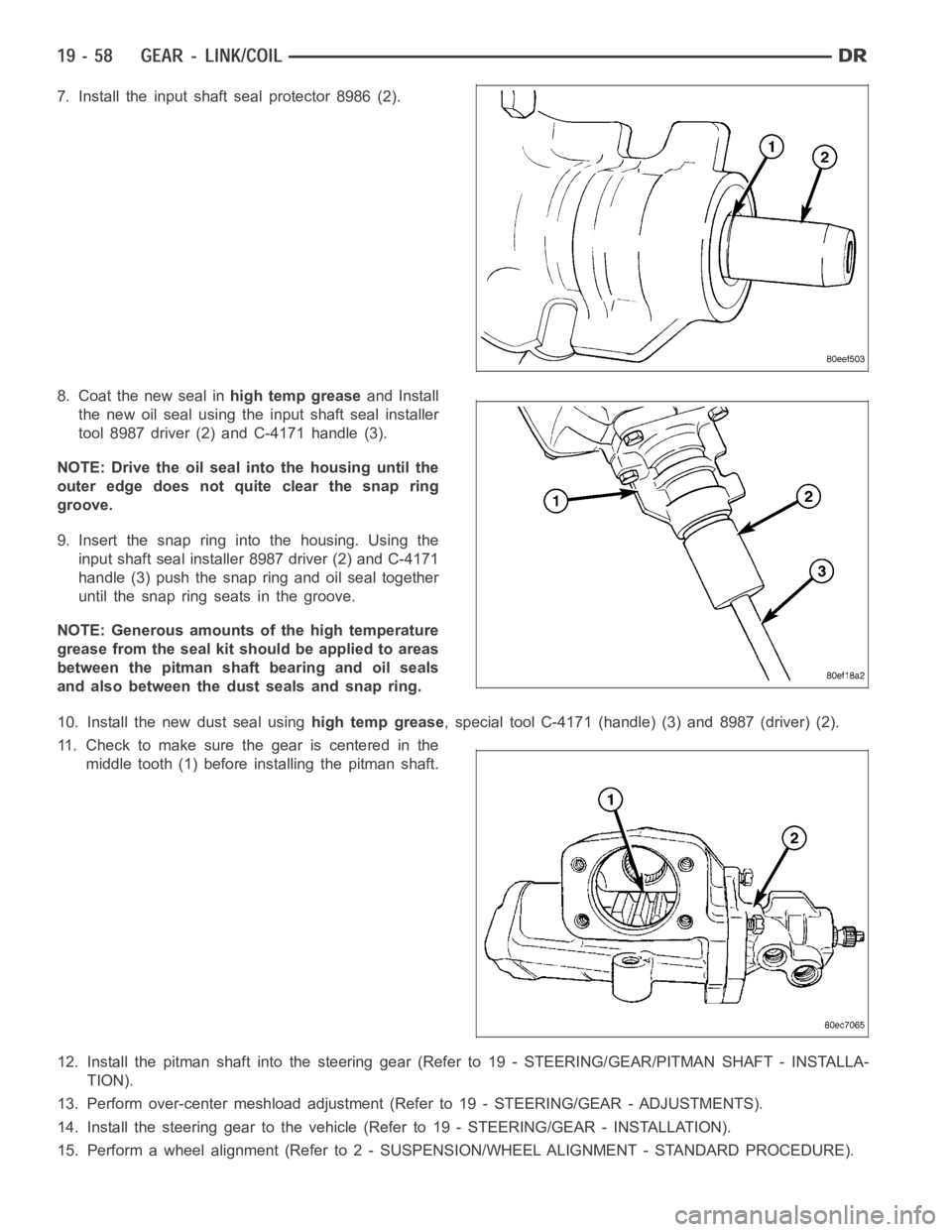
7. Install the input shaft seal protector 8986 (2).
8. Coat the new seal inhigh temp greaseand Install
the new oil seal using the input shaft seal installer
tool 8987 driver (2) and C-4171 handle (3).
NOTE: Drive the oil seal into the housing until the
outer edge does not quite clear the snap ring
groove.
9. Insert the snap ring into the housing. Using the
input shaft seal installer 8987 driver (2) and C-4171
handle (3) push the snap ring and oil seal together
until the snap ring seats in the groove.
NOTE: Generous amounts of the high temperature
grease from the seal kit should be applied to areas
between the pitman shaft bearing and oil seals
and also between the dust seals and snap ring.
10. Install the new dust seal usinghigh temp grease, special tool C-4171 (handle) (3) and 8987 (driver) (2).
11. Check to make sure the gear is centered in the
middle tooth (1) before installing the pitman shaft.
12. Install the pitman shaft into the steering gear (Refer to 19 - STEERING/GEAR/PITMAN SHAFT - INSTALLA-
TION).
13. Perform over-center meshload adjustment (Refer to 19 - STEERING/GEAR- ADJUSTMENTS).
14. Install the steering gear to the vehicle (Refer to 19 - STEERING/GEAR - INSTALLATION).
15. Perform a wheel alignment (Refer to2 - SUSPENSION/WHEEL ALIGNMENT - STANDARD PROCEDURE).
Page 2465 of 5267
7. Remove the pitman shaft cover (3) bolts.
NOTE: The pitman shaft will not clear the housing
if it is not centered.
8. Remove the pitman shaft (1) from the gear.
9. Remove the cover (3) if needed by loosing the
adjuster nut (4). Then removing the cover from the
pitman shaft.
INSTALLATION
GAS
1. Coat the seal withpower steering fluid.
2. Install pitman shaft (1) into the steering gear until it
fully seats into the bearing.
3. Install the new cover bolts and tighten to 68 Nꞏm
(50 ft. lbs.).
4. Perform over-center meshload adjustment, (Refer
to 19 - STEERING/GEAR - ADJUSTMENTS).
5. Install the pitman arm (Refer to 19 - STEERING/LINKAGE/PITMAN ARM - INSTALLATION).
6. Perform a wheel alignment (Refer to 2- SUSPENSION/WHEEL ALIGNMENT - STANDARD PROCEDURE).
Page 2466 of 5267
DIESEL
1. Coat the seal withpower steering fluid.
2. Install the pitman shaft (1) into the steering gear
until it fully seats into the bearing.
3. Install the new cover bolts and tighten to 68 Nꞏm
(50 ft. lbs.).
4. Perform over-center meshload adjustment (Refer to
19 - STEERING/GEAR - ADJUSTMENTS).
5. Install the steering gear (Refer to 19 - STEERING/GEAR - INSTALLATION).
6. Install the pitman arm (Refer to 19 - STEERING/LINKAGE/PITMAN ARM - INSTALLATION).
7. Perform a wheel alignment (Refer to 2- SUSPENSION/WHEEL ALIGNMENT - STANDARD PROCEDURE).