2006 DODGE RAM SRT-10 seats
[x] Cancel search: seatsPage 1627 of 5267
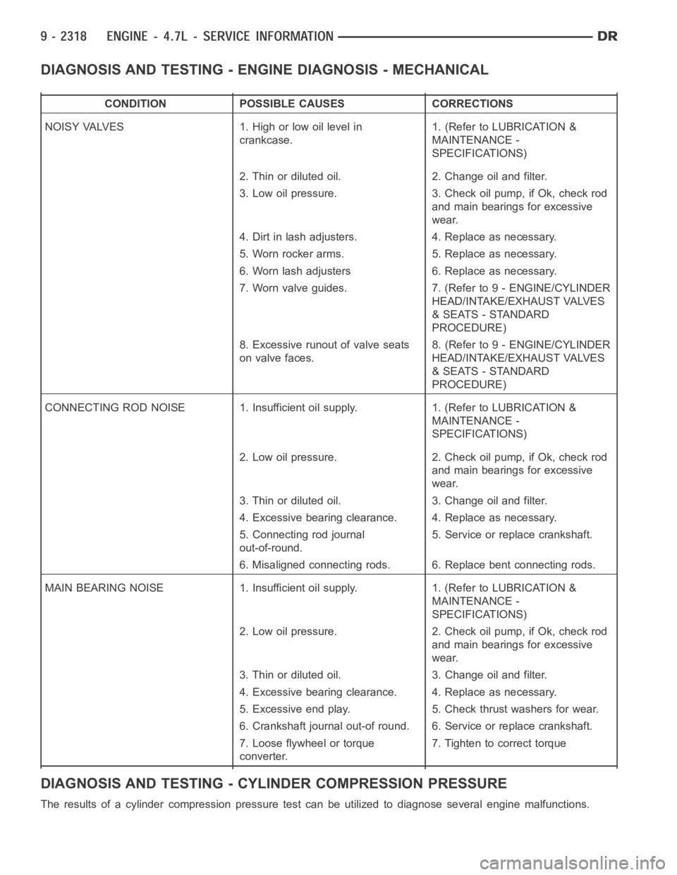
DIAGNOSIS AND TESTING - ENGINE DIAGNOSIS - MECHANICAL
CONDITION POSSIBLE CAUSES CORRECTIONS
NOISY VALVES 1. High or low oil level in
crankcase.1. (Refer to LUBRICATION &
MAINTENANCE -
SPECIFICATIONS)
2. Thin or diluted oil. 2. Change oil and filter.
3. Low oil pressure. 3. Check oil pump, if Ok, check rod
and main bearings for excessive
wear.
4. Dirt in lash adjusters. 4. Replace as necessary.
5. Worn rocker arms. 5. Replace as necessary.
6. Worn lash adjusters 6. Replace as necessary.
7. Worn valve guides. 7. (Refer to 9 - ENGINE/CYLINDER
HEAD/INTAKE/EXHAUST VALVES
& SEATS - STANDARD
PROCEDURE)
8. Excessive runout of valve seats
on valve faces.8. (Refer to 9 - ENGINE/CYLINDER
HEAD/INTAKE/EXHAUST VALVES
& SEATS - STANDARD
PROCEDURE)
CONNECTING ROD NOISE 1. Insufficient oil supply. 1. (Refer to LUBRICATION&
MAINTENANCE -
SPECIFICATIONS)
2. Low oil pressure. 2. Check oil pump, if Ok, check rod
and main bearings for excessive
wear.
3. Thin or diluted oil. 3. Change oil and filter.
4. Excessive bearing clearance. 4. Replace as necessary.
5. Connecting rod journal
out-of-round.5. Service or replace crankshaft.
6. Misaligned connecting rods. 6. Replace bent connecting rods.
MAIN BEARING NOISE 1. Insufficient oil supply. 1. (Refer to LUBRICATION &
MAINTENANCE -
SPECIFICATIONS)
2. Low oil pressure. 2. Check oil pump, if Ok, check rod
and main bearings for excessive
wear.
3. Thin or diluted oil. 3. Change oil and filter.
4. Excessive bearing clearance. 4. Replace as necessary.
5. Excessive end play. 5. Check thrust washers for wear.
6. Crankshaft journal out-of round. 6. Service or replace crankshaft.
7. Loose flywheel or torque
converter.7. Tighten to correct torque
DIAGNOSIS AND TESTING - CYLINDER COMPRESSION PRESSURE
The results of a cylinder compressionpressure test can be utilized to diagnose several engine malfunctions.
Page 1659 of 5267
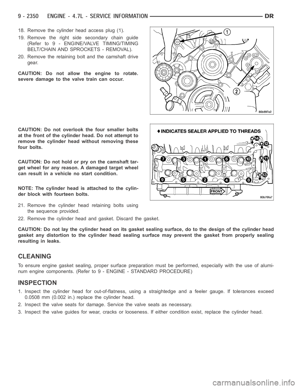
18. Remove the cylinder head access plug (1).
19. Remove the right side secondary chain guide
(Refer to 9 - ENGINE/VALVE TIMING/TIMING
BELT/CHAIN AND SPROCKETS - REMOVAL).
20. Remove the retaining bolt and the camshaft drive
gear.
CAUTION: Do not allow the engine to rotate.
severe damage to the valve train can occur.
CAUTION: Do not overlook the four smaller bolts
at the front of the cylinder head. Do not attempt to
remove the cylinder head without removing these
four bolts.
CAUTION: Do not hold or pry on the camshaft tar-
get wheel for any reason. A damaged target wheel
can result in a vehicle no start condition.
NOTE: The cylinder head is attached to the cylin-
der block with fourteen bolts.
21. Remove the cylinder head retaining bolts using
the sequence provided.
22. Remove the cylinder head and gasket. Discard the gasket.
CAUTION: Do not lay the cylinder head on its gasket sealing surface, do to the design of the cylinder head
gasket any distortion to the cylinder head sealing surface may prevent thegasket from properly sealing
resulting in leaks.
CLEANING
To ensure engine gasket sealing, proper surface preparation must be performed, especially with the use of alumi-
num engine components. (Refer to 9 - ENGINE - STANDARD PROCEDURE)
INSPECTION
1. Inspect the cylinder head for out-of-flatness, using a straightedge and a feeler gauge. If tolerances exceed
0.0508 mm (0.002 in.) replace the cylinder head.
2. Inspect the valve seats for damage. Service the valve seats as necessary.
3. Inspect the valve guides for wear, cracks or looseness. If either condition exist, replace the cylinder head.
Page 1660 of 5267
INSTALLATION
INSTALLATION - LEFT CYLINDER HEAD
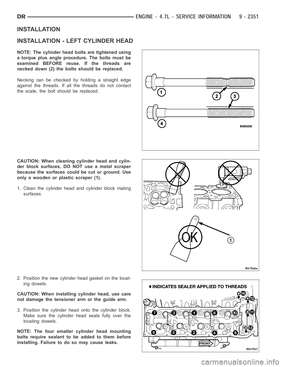
NOTE: The cylinder head bolts are tightened using
a torque plus angle procedure. The bolts must be
examined BEFORE reuse. If the threads are
necked down (2) the bolts should be replaced.
Necking can be checked by holding a straight edge
against the threads. If all the threads do not contact
the scale, the bolt should be replaced.
CAUTION: When cleaning cylinder head and cylin-
der block surfaces, DO NOT use a metal scraper
because the surfaces could be cut or ground. Use
only a wooden or plastic scraper (1).
1. Clean the cylinder head and cylinder block mating
surfaces.
2. Position the new cylinder head gasket on the locat-
ing dowels.
CAUTION: When installing cylinder head, use care
not damage the tensioner arm or the guide arm.
3. Position the cylinder head onto the cylinder block.
Make sure the cylinder head seats fully over the
locating dowels.
NOTE: The four smaller cylinder head mounting
bolts require sealant to be added to them before
installing. Failure to do so may cause leaks.
Page 1663 of 5267
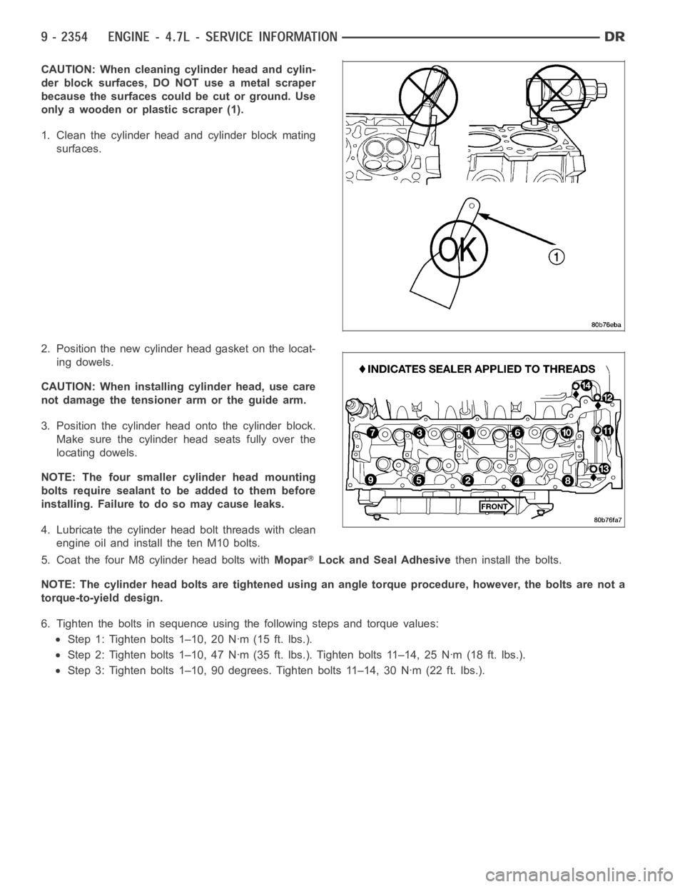
CAUTION: When cleaning cylinder head and cylin-
der block surfaces, DO NOT use a metal scraper
because the surfaces could be cut or ground. Use
only a wooden or plastic scraper (1).
1. Clean the cylinder head and cylinder block mating
surfaces.
2. Position the new cylinder head gasket on the locat-
ing dowels.
CAUTION: When installing cylinder head, use care
not damage the tensioner arm or the guide arm.
3. Position the cylinder head onto the cylinder block.
Make sure the cylinder head seats fully over the
locating dowels.
NOTE: The four smaller cylinder head mounting
bolts require sealant to be added to them before
installing. Failure to do so may cause leaks.
4. Lubricate the cylinder head bolt threads with clean
engine oil and install the ten M10 bolts.
5. Coat the four M8 cylinder head bolts withMopar
Lock and Seal Adhesivethen install the bolts.
NOTE: The cylinder head bolts are tightened using an angle torque procedure, however, the bolts are not a
torque-to-yield design.
6. Tighten the bolts in sequence using the following steps and torque values:
Step 1: Tighten bolts 1–10, 20 Nꞏm (15 ft. lbs.).
Step 2: Tighten bolts 1–10, 47 Nꞏm (35 ft. lbs.). Tighten bolts 11–14, 25 Nꞏm(18 ft. lbs.).
Step 3: Tighten bolts 1–10, 90 degrees. Tighten bolts 11–14, 30 Nꞏm (22 ft. lbs.).
Page 1680 of 5267
VALVES & SEATS - INTAKE/EXHAUST
DESCRIPTION
The valves are made of heat resistant steel and have chrome plated stems to prevent scuffing. Each valve is actu-
ated by a roller rocker arm which pivots on a stationary lash adjuster. All valves use three bead lock keepers to
retain the springs and promote valve rotation.
REMOVAL
NOTE: The cylinder heads must be removed in
order to perform this procedure.
1. Remove rocker arms and lash adjusters (Refer to 9
- ENGINE/CYLINDER HEAD/ROCKER ARM /
ADJUSTER ASSY - REMOVAL).
2. Remove the camshaft bearing caps and the cam-
shaft.
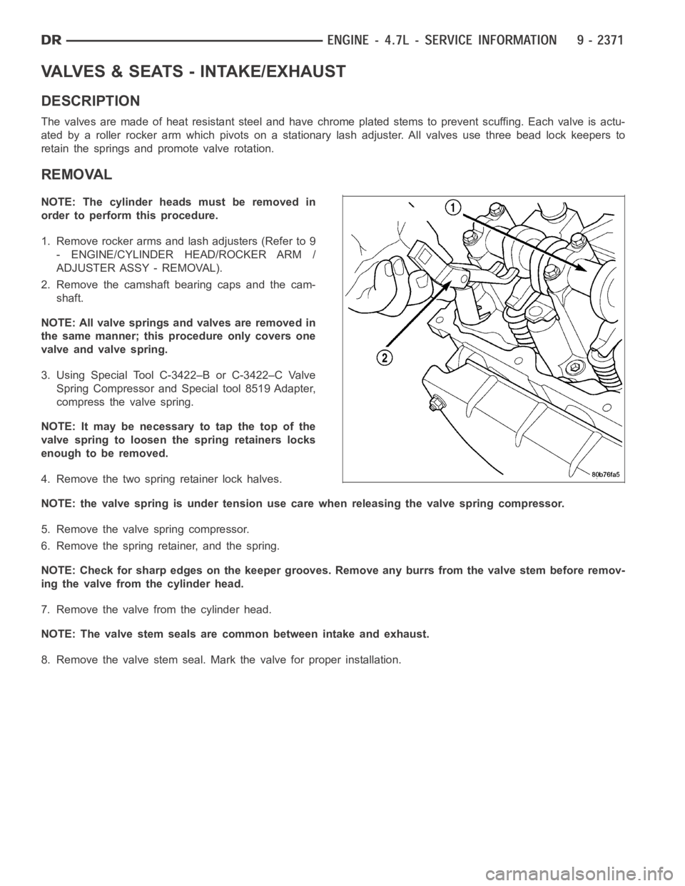
NOTE: All valve springs and valves are removed in
the same manner; this procedure only covers one
valve and valve spring.
3. Using Special Tool C-3422–B or C-3422–C Valve
Spring Compressor and Special tool 8519 Adapter,
compress the valve spring.
NOTE: It may be necessary to tap the top of the
valve spring to loosen the spring retainers locks
enough to be removed.
4. Remove the two spring retainer lock halves.
NOTE: the valve spring is under tension use care when releasing the valve spring compressor.
5. Remove the valve spring compressor.
6. Remove the spring retainer, and the spring.
NOTE: Check for sharp edges on the keeper grooves. Remove any burrs from thevalvestembeforeremov-
ing the valve from the cylinder head.
7. Remove the valve from the cylinder head.
NOTE: The valve stem seals are common between intake and exhaust.
8. Remove the valve stem seal. Mark the valve for proper installation.
Page 1703 of 5267
INSTALLATION
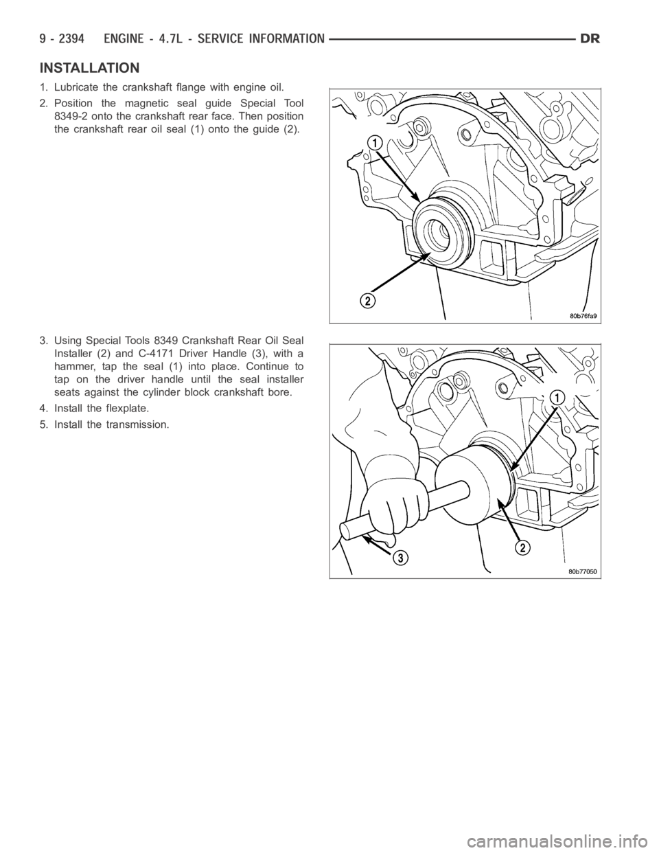
1. Lubricate the crankshaft flange with engine oil.
2. Position the magnetic seal guide Special Tool
8349-2 onto the crankshaft rear face. Then position
the crankshaft rear oil seal (1) onto the guide (2).
3. Using Special Tools 8349 Crankshaft Rear Oil Seal
Installer (2) and C-4171 Driver Handle (3), with a
hammer, tap the seal (1) into place. Continue to
tap on the driver handle until the seal installer
seats against the cylinder block crankshaft bore.
4. Install the flexplate.
5. Install the transmission.
Page 1756 of 5267
page page
ENGINE - 5.7L - SERVICE INFORMATION
DESCRIPTION ............................. 2449
DIAGNOSIS AND TESTING
DIAGNOSIS AND TESTING - ENGINE
DIAGNOSIS - INTRODUCTION............. 2449
DIAGNOSIS AND TESTING - ENGINE
DIAGNOSIS - PERFORMANCE............. 2449
DIAGNOSIS AND TESTING - ENGINE
DIAGNOSIS - MECHANICAL............... 2451
DIAGNOSIS AND TESTING - CYLINDER
COMPRESSION PRESSURE............... 2451
DIAGNOSIS AND TESTING - CYLINDER
COMBUSTION PRESSURE LEAKAGE...... 2452
DIAGNOSIS AND TESTING - ENGINE
DIAGNOSIS - LUBRICATION............... 2453
DIAGNOSIS AND TESTING - ENGINE
DIAGNOSIS - MECHANICAL............... 2453
STANDARD PROCEDURE
STANDARD PROCEDURE - REPAIR
DAMAGED OR WORN THREADS.......... 2456
STANDARD PROCEDURE—HYDROSTATIC
LOCK.................................... 2456
REMOVAL ................................. 2457
INSTALLATION ............................. 2462
SPECIFICATIONS
5.7L ENGINE ............................. 2467
TORQUE ................................. 2472
SPECIAL TOOLS
5.7L ENGINE ............................. 2475
ELEMENT - AIR CLEANER
REMOVAL ................................. 2478
INSTALLATION ............................. 2479
CYLINDER HEAD
OPERATION—CYLINDER HEAD ............. 2481
DIAGNOSIS AND TESTING—CYLINDER HEAD
GASKET FAILURE........................ 2481
REMOVAL ................................. 2482
CLEANING ................................. 2484
INSPECTION ............................... 2484
INSTALLATION ............................. 2485
COVER - CYLINDER HEAD
REMOVAL ................................. 2490
INSTALLATION ............................. 2493
VALVES & SEATS - INTAKE/EXHAUST
DESCRIPTION
DESCRIPTION - VALVE GUIDES ........... 2496
DESCRIPTION ........................... 2496
STANDARD PROCEDURE - REFACING ....... 2496
REMOVAL ................................. 2497
INSTALLATION ............................. 2497ROCKER ARM
REMOVAL ................................. 2498
INSTALLATION ............................. 2500
SEALS - VALVE GUIDE
DESCRIPTION ............................. 2503
SPRINGS - VALVE
REMOVAL ................................. 2504
INSTALLATION ............................. 2510
ENGINE BLOCK
CLEANING ................................. 2515
INSPECTION............................... 2515
CAMSHAFT
REMOVAL
REMOVAL - CAMSHAFT CORE HOLE PLUG . 2516
REMOVAL - CAMSHAFT ................... 2516
INSPECTION............................... 2520
INSTALLATION
INSTALLATION - CAMSHAFT CORE HOLE
PLUG.................................... 2520
INSTALLATION - CAMSHAFT .............. 2521
CRANKSHAFT
REMOVAL ................................. 2527
INSTALLATION ............................. 2531
BEARINGS - CRANKSHAFT MAIN
STANDARD PROCEDURE - CRANKSHAFT
MAIN BEARING - FITTING ................. 2536
INSPECTION............................... 2536
SEAL - CRANKSHAFT OIL - FRONT
REMOVAL ................................. 2537
INSTALLATION ............................. 2538
SEAL - CRANKSHAFT OIL - REAR
DIAGNOSIS AND TESTING - REAR SEAL
AREA LEAKS . ............................ 2539
REMOVAL ................................. 2539
INSTALLATION ............................. 2540
RETAINER - CRANK REAR OIL - SEAL
REMOVAL ................................. 2541
INSTALLATION ............................. 2541
FLEX PLATE
REMOVAL ................................. 2542
INSTALLATION ............................. 2542
TAPPETS - HYDRAULIC ROLLER
DIAGNOSIS AND TESTING - HYDRAULIC
TAPPETS ................................ 2543
REMOVAL ................................. 2543
INSTALLATION ............................. 2544
PISTON & CONNECTING ROD
DESCRIPTION ............................. 2546
STANDARD PROCEDURE - PISTON FITTING . 2546
REMOVAL ................................. 2547
CLEANING ................................. 2548
Page 1760 of 5267
DIAGNOSIS AND TESTING - ENGINE DIAGNOSIS - MECHANICAL
CONDITION POSSIBLE CAUSES CORRECTIONS
NOISY VALVES 1. High or low oil level in
crankcase.1. (Refer to LUBRICATION &
MAINTENANCE -
SPECIFICATIONS)
2. Thin or diluted oil. 2. Change oil and filter.
3. Low oil pressure. 3. Check oil pump, if Ok, check rod
and main bearings for excessive
wear.
4. Dirt in lash adjusters. 4. Replace as necessary.
5. Worn rocker arms. 5. Replace as necessary.
6. Worn lash adjusters 6. Replace as necessary.
7. Worn valve guides. 7. (Refer to 9 - ENGINE/CYLINDER
HEAD/INTAKE/EXHAUST VALVES
& SEATS - STANDARD
PROCEDURE)
8. Excessive runout of valve seats
on valve faces.8. (Refer to 9 - ENGINE/CYLINDER
HEAD/INTAKE/EXHAUST VALVES
& SEATS - STANDARD
PROCEDURE)
CONNECTING ROD NOISE 1. Insufficient oil supply. 1. (Refer to LUBRICATION&
MAINTENANCE -
SPECIFICATIONS)
2. Low oil pressure. 2. Check oil pump, if Ok, check rod
and main bearings for excessive
wear.
3. Thin or diluted oil. 3. Change oil and filter.
4. Excessive bearing clearance. 4. Replace as necessary.
5. Connecting rod journal
out-of-round.5. Service or replace crankshaft.
6. Misaligned connecting rods. 6. Replace bent connecting rods.
MAIN BEARING NOISE 1. Insufficient oil supply. 1. (Refer to LUBRICATION &
MAINTENANCE -
SPECIFICATIONS)
2. Low oil pressure. 2. Check oil pump, if Ok, check rod
and main bearings for excessive
wear.
3. Thin or diluted oil. 3. Change oil and filter.
4. Excessive bearing clearance. 4. Replace as necessary.
5. Excessive end play. 5. Check thrust washers for wear.
6. Crankshaft journal out-of round. 6. Service or replace crankshaft.
7. Loose flywheel or torque
converter.7. Tighten to correct torque
DIAGNOSIS AND TESTING - CYLINDER COMPRESSION PRESSURE
The results of a cylinder compressionpressure test can be utilized to diagnose several engine malfunctions.