Page 2346 of 5267
SPECIAL TOOLS
DIESELFUELSYSTEM
FUEL PRESSURE TEST ADAPTER - # 9012
FUEL PRESSURE TEST ADAPTER - #9014
FUEL INJECTOR REMOVER - #9010
PRESSURE CAP - #9011
FUEL PRESSURE TEST ADAPTER - #9013
FUEL INJECTOR TUBE (CONNECTOR) REMOVER -
#9015
LOCKRING REMOVER/INSTALLER #9340
Page 2348 of 5267
FILTER - FUEL / WATER SEPARATOR
DESCRIPTION
The fuel filter/water separator assembly is located on left side of engineabove the starter motor. The assembly also
includes the fuel heater, Water-In-Fuel (WIF) sensor and a screened banjobolt attached at the bottom of the fuel
filter canister.
OPERATION
The fuel filter/water separator protects the fuel injection pump by removing water and contaminants from the fuel.
The construction of the filter/separator allows fuel to pass through it, but helps prevent moisture (water) from doing
so. Moisture collects at the bottom of the canister.
Refer to the maintenance schedules in the owners manual for the recommended fuel filter replacement intervals.
For draining of water from canister, refer to Fuel Filter/Water SeparatorRemoval/Installation section.
There is a screened banjo bolt that is attached at the bottom of the fuel filter canister. It provides additional filtering
for the high pressure fuel system components.
A Water-In-Fuel (WIF) sensor is attached to the side of fuel filter housing. Refer to Water-In-Fuel Sensor Descrip-
tion/Operation.
The fuel heater is installed into the top of the filter/separator housing.Refer to Fuel Heater Description/Operation.
REMOVAL
Refer to maintenance schedules in this manual, or the
Owner’s Manual for recommended fuel filter replace-
ment intervals.
Draining water from fuel filter/water separator
housing:
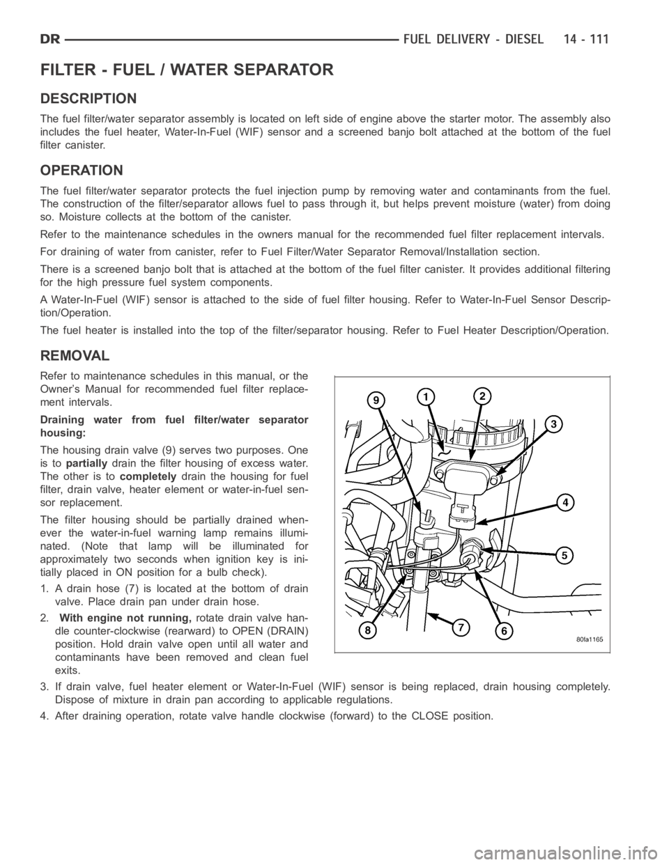
The housing drain valve (9) serves two purposes. One
is topartiallydrain the filter housing of excess water.
The other is tocompletelydrain the housing for fuel
filter, drain valve, heater element or water-in-fuel sen-
sor replacement.
The filter housing should be partially drained when-
ever the water-in-fuel warning lamp remains illumi-
nated. (Note that lamp will be illuminated for
approximately two seconds when ignition key is ini-
tially placed in ON position for a bulb check).
1. A drain hose (7) is located at the bottom of drain
valve. Place drain pan under drain hose.
2.With engine not running,rotate drain valve han-
dle counter-clockwise (rearward) to OPEN (DRAIN)
position. Hold drain valve open until all water and
contaminants have been removed and clean fuel
exits.
3. If drain valve, fuel heater element or Water-In-Fuel (WIF) sensor is being replaced, drain housing completely.
Dispose of mixture in drain pan according to applicable regulations.
4. After draining operation, rotate valve handle clockwise (forward) to the CLOSE position.
Page 2349 of 5267
5.Fuel Filter Replacement:The fuel filter is located
inside of the fuel filter housing.
a. Clean all debris from around canister.
b. Remove filter lid (1) using a socket. Attach
socket to large hex (2) on top of lid. Rotate
counterclockwise for removal. Remove O-ring.
Discard O-ring.
c. Remove filter element by twisting element side-
ways from filter lid.
6.Water-In-Fuel (WIF) Sensor Replacement:The
WIF sensor (5) is located on the side of the fuel fil-
ter housing.
a. Disconnect electrical connector at sensor.
b. Clean area around sensor.
c. Remove sensor by rotating counterclockwise.
d. Check condition of sensor O-ring. Replace if
damaged.
Page 2350 of 5267
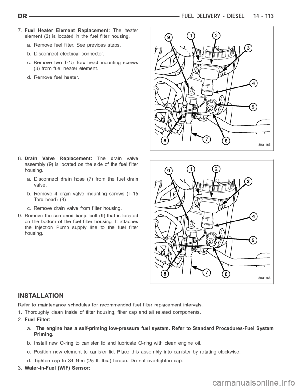
7.Fuel Heater Element Replacement:The heater
element (2) is located in the fuel filter housing.
a. Remove fuel filter. See previous steps.
b. Disconnect electrical connector.
c. Remove two T-15 Torx head mounting screws
(3) from fuel heater element.
d. Remove fuel heater.
8.Drain Valve Replacement:The drain valve
assembly (9) is located on the side of the fuel filter
housing.
a. Disconnect drain hose (7) from the fuel drain
valve.
b. Remove 4 drain valve mounting screws (T-15
Torx head) (8).
c. Remove drain valve from filter housing.
9. Remove the screened banjo bolt (9) that is located
on the bottom of the fuel filter housing. It attaches
the Injection Pump supply line to the fuel filter
housing.
INSTALLATION
Refer to maintenance schedules for recommended fuel filter replacement intervals.
1. Thoroughly clean inside of filter housing, filter cap and all related components.
2.Fuel Filter:
a.The engine has a self-priming low-pressure fuel system. Refer to StandardProcedures-Fuel System
Priming.
b. Install new O-ring to canister lid and lubricate O-ring with clean engine oil.
c. Position new element to canister lid. Place this assembly into canisterby rotating clockwise.
d. Tighten cap to 34 Nꞏm (25 ft. lbs.) torque. Do not overtighten cap.
3.Water-In-Fuel (WIF) Sensor:
Page 2369 of 5267
TA N K - F U E L
DESCRIPTION
The fuel tank is similar to the tank used with gasoline powered models. The tank is equipped with a separate fuel
return line and a different fuel tank module for diesel powered models. Theelectric fuel transfer pump (lift pump) is
attached to the fuel pump module. Refer to Fuel Tank Module for additional information.
REMOVAL
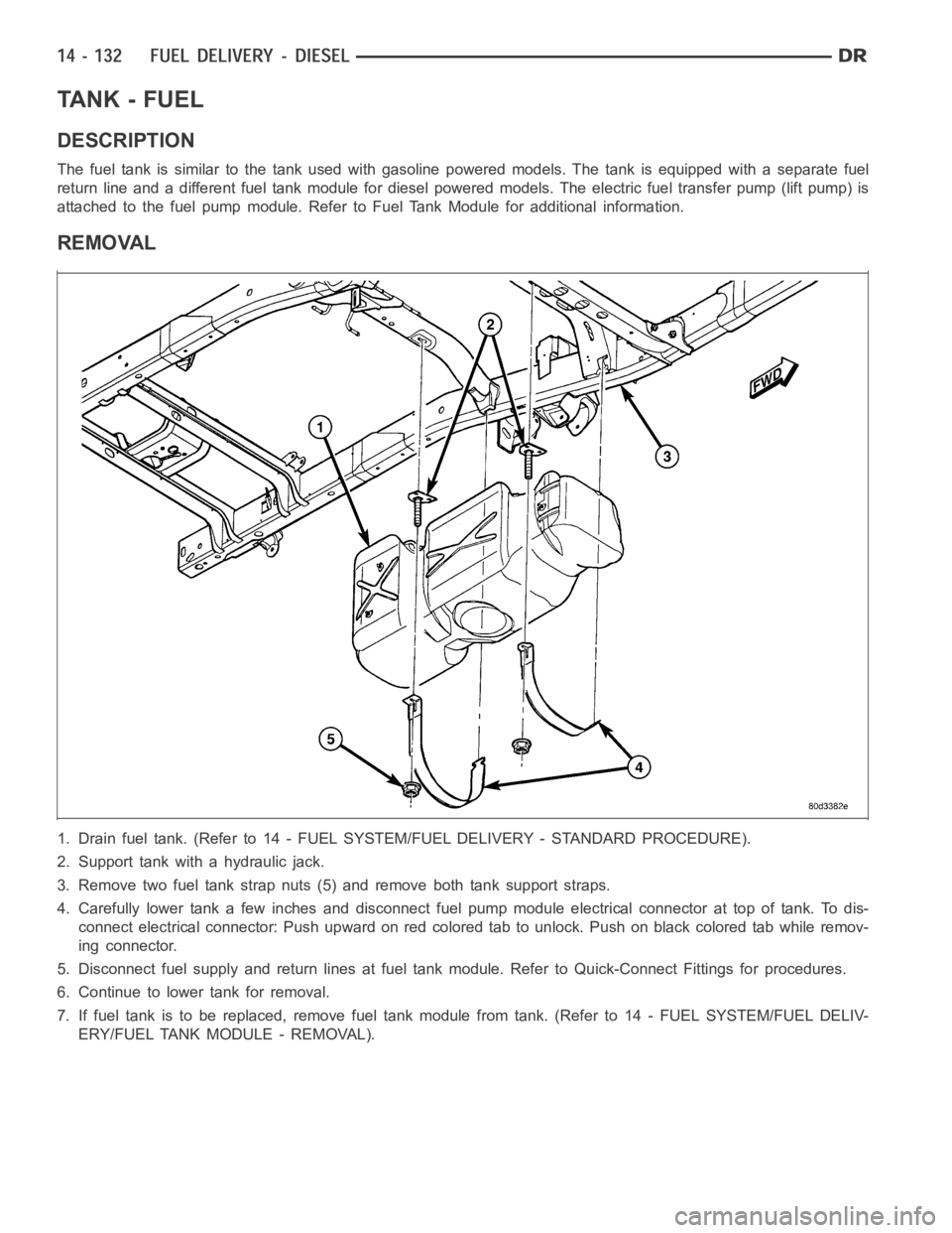
1. Drain fuel tank. (Refer to 14 - FUEL SYSTEM/FUEL DELIVERY - STANDARD PROCEDURE).
2. Support tank with a hydraulic jack.
3. Remove two fuel tank strap nuts (5) and remove both tank support straps.
4. Carefully lower tank a few inches and disconnect fuel pump module electrical connector at top of tank. To dis-
connect electrical connector: Push upward on red colored tab to unlock. Push on black colored tab while remov-
ing connector.
5. Disconnect fuel supply and return lines at fuel tank module. Refer to Quick-Connect Fittings for procedures.
6. Continue to lower tank for removal.
7. If fuel tank is to be replaced, remove fuel tank module from tank. (Refer to 14 - FUEL SYSTEM/FUEL DELIV-
ERY/FUEL TANK MODULE - REMOVAL).
Page 2371 of 5267
MODULE - FUEL TANK
DESCRIPTION
.
The fuel tank module is installed in the top of the fuel tank. The fuel tank module contains the following compo-
nents:
An electric fuel transfer (lift) pump
Fuel reservoir
A separate in-tank fuel filter
Fuel gauge sending unit (fuel level sensor)
Fuel supply line connection
A special lockring to retain module to fuel tank
Fuel return line connection
OPERATION
Refer to Fuel Gauge Sending Unit.
REMOVAL
1. Drain and remove fuel tank (Refer to 14 - FUEL
SYSTEM/FUEL DELIVERY/FUEL TANK -
REMOVAL).
2. Note rotational position of module before attempt-
ing removal. An indexing arrow is located on top of
module for this purpose.
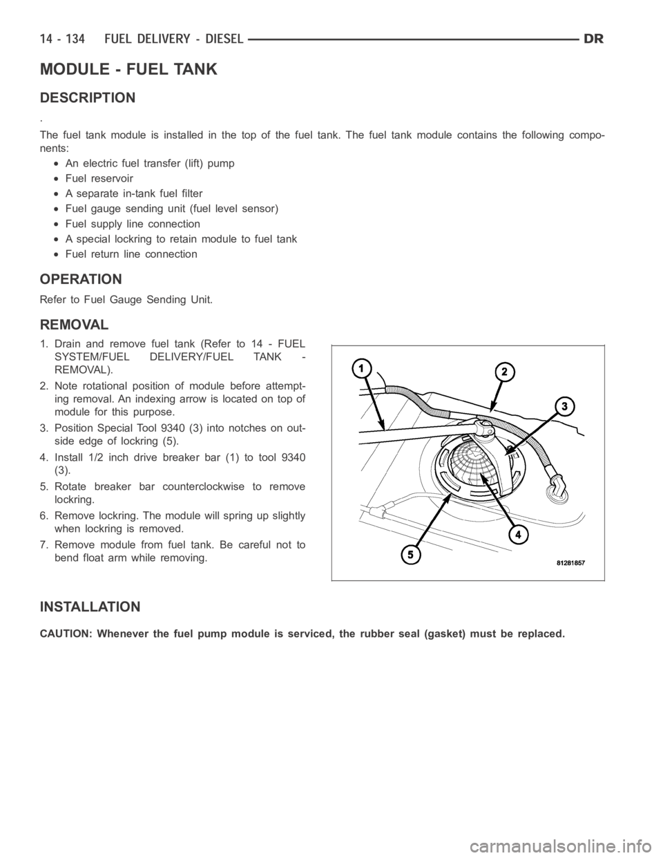
3. Position Special Tool 9340 (3) into notches on out-
side edge of lockring (5).
4. Install 1/2 inch drive breaker bar (1) to tool 9340
(3).
5. Rotate breaker bar counterclockwise to remove
lockring.
6. Remove lockring. The module will spring up slightly
when lockring is removed.
7. Remove module from fuel tank. Be careful not to
bend float arm while removing.
INSTALLATION
CAUTION: Whenever the fuel pump module is serviced, the rubber seal (gasket) must be replaced.
Page 2372 of 5267
1. Using a new seal (gasket), position fuel pump mod-
uleintoopeninginfueltank.
2. Position lockring (5) over top of fuel pump module.
3. Rotate module until embossed alignment arrow
points to center alignment mark. This step must be
performed to prevent float from contacting side of
fuel tank. Also be sure fuel fitting on top of pump
module is pointed to drivers side of vehicle.
4. Install Special Tool 9340 (3) to lockring.
5. Install 1/2 inch drive breaker (1) into Special Tool
9340 (3).
6. Tighten lockring (clockwise) until all seven notches
have engaged.
7. Install fuel tank (Refer to 14 - FUEL SYSTEM/
FUEL DELIVERY/FUEL TANK - INSTALLATION).
Page 2384 of 5267
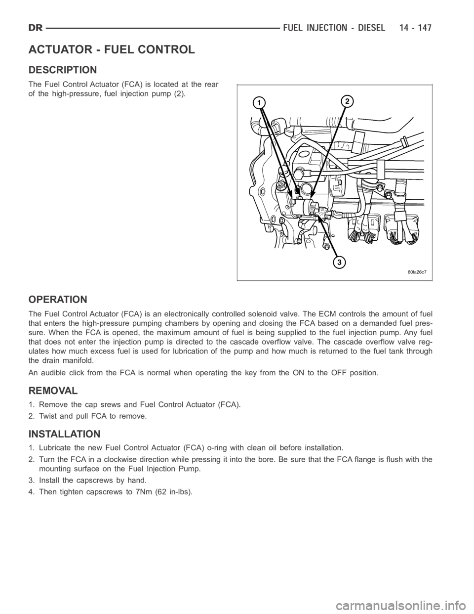
ACTUATOR - FUEL CONTROL
DESCRIPTION
The Fuel Control Actuator (FCA) is located at the rear
of the high-pressure, fuel injection pump (2).
OPERATION
The Fuel Control Actuator (FCA) is an electronically controlled solenoidvalve. The ECM controls the amount of fuel
that enters the high-pressure pumping chambers by opening and closing theFCA based on a demanded fuel pres-
sure. When the FCA is opened, the maximum amount of fuel is being supplied tothe fuel injection pump. Any fuel
that does not enter the injection pump is directed to the cascade overflow valve. The cascade overflow valve reg-
ulates how much excess fuel is used for lubrication of the pump and how much is returned to the fuel tank through
the drain manifold.
An audible click from the FCA is normal when operating the key from the ON to the OFF position.
REMOVAL
1. Remove the cap srews and Fuel Control Actuator (FCA).
2. Twist and pull FCA to remove.
INSTALLATION
1. Lubricate the new Fuel Control Actuator (FCA) o-ring with clean oil before installation.
2. Turn the FCA in a clockwise direction while pressing it into the bore. Be sure that the FCA flange is flush with the
mounting surface on the Fuel Injection Pump.
3. Install the capscrews by hand.
4. Then tighten capscrews to 7Nm (62 in-lbs).