Page 2438 of 5267
INSTALLATION
1. Install the upper steering coupling shaft (3) to the
vehicle.
2. Install the upper steering coupling shaft seal (2) by
pushing it in securing the four tangs (1) to the
panel.
NOTE: A new steering coupling shaft pinch bolt
for the upper and lower shafts must be used.
3. Install the steering coupler shaft (1) to the column.
4. Install the upper pinch bolt (3) use new bolt and
tighten to 57 N.m (42 ft.lbs).
5. Install the shaft to the lower coupler (1).
6. Install the lower pinch bolt (1) use new bolt and
tighten to 57 N.m (42 ft.lbs).
7. Unlock the steering wheel.
8. Reconnect the negative battery cable.
Page 2439 of 5267

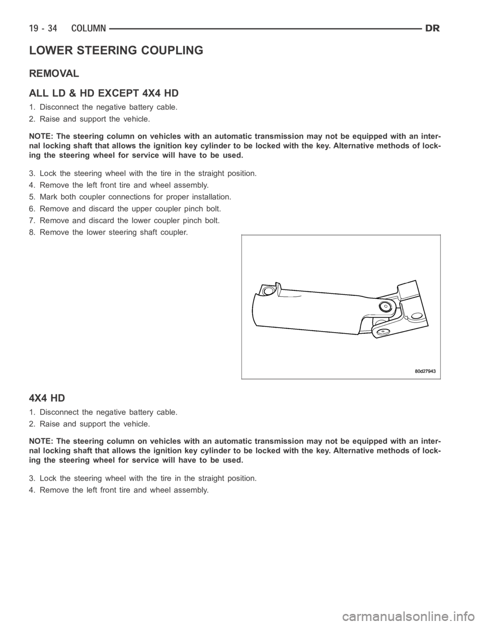
LOWER STEERING COUPLING
REMOVAL
ALLLD&HDEXCEPT4X4HD
1. Disconnect the negative battery cable.
2. Raise and support the vehicle.
NOTE: The steering column on vehicles with an automatic transmission may not be equipped with an inter-
nal locking shaft that allows the ignition key cylinder to be locked with the key. Alternative methods of lock-
ing the steering wheel for service will have to be used.
3. Lock the steering wheel with the tire in the straight position.
4. Remove the left front tire and wheel assembly.
5. Mark both coupler connections for proper installation.
6. Remove and discard the upper coupler pinch bolt.
7. Remove and discard the lower coupler pinch bolt.
8. Remove the lower steering shaft coupler.
4X4 HD
1. Disconnect the negative battery cable.
2. Raise and support the vehicle.
NOTE: The steering column on vehicles with an automatic transmission may not be equipped with an inter-
nal locking shaft that allows the ignition key cylinder to be locked with the key. Alternative methods of lock-
ing the steering wheel for service will have to be used.
3. Lock the steering wheel with the tire in the straight position.
4. Remove the left front tire and wheel assembly.
Page 2441 of 5267
INSTALLATION
ALLLD&HDEXCEPT4X4HD
1. Install the coupler to the steering rack & pinion
using the marks made in the removal process.
2. Install the coupler to the intermediate shaft using
the marks made in the removal process.
NOTE: New pinch bolts must be used for reinstal-
lation.
3. Install the lower pinch bolt and tighten to 57 Nꞏm
(42 ft. lbs.).SRT10. Tighten to 38 Nꞏm (28 ft.
lbs.).
4. Install the upper pinch bolt and tighten to 57 Nꞏm
(42 ft. lbs.).
5. Install the left front tire and wheel assembly (Refer to 22 - TIRES/WHEELS/WHEELS - STANDARD PROCE-
DURE).
6. Lower the vehicle.
7. Reconnect the negative battery cable.
8. Unlock the steering wheel.
4X4 HD
1. Install the coupler (2) to the steering gear (3).
Page 2442 of 5267
2. Install the coupler (3) to the intermediate shaft (2).
NOTE: New pinch bolts must be used for reinstal-
lation.
3. Install the lower pinch bolt (3) and tighten to 28
Nꞏm (250 in. lbs.).
4. Install the upper pinch bolt (1) and tighten to 57
Nꞏm (42 ft. lbs.).
5. Install the left front tire and wheel assembly (Refer to 22 - TIRES/WHEELS/WHEELS - STANDARD PROCE-
DURE).
6. Lower the vehicle.
7. Reconnect the negative battery cable.
8. Unlock the steering wheel.
Page 2444 of 5267

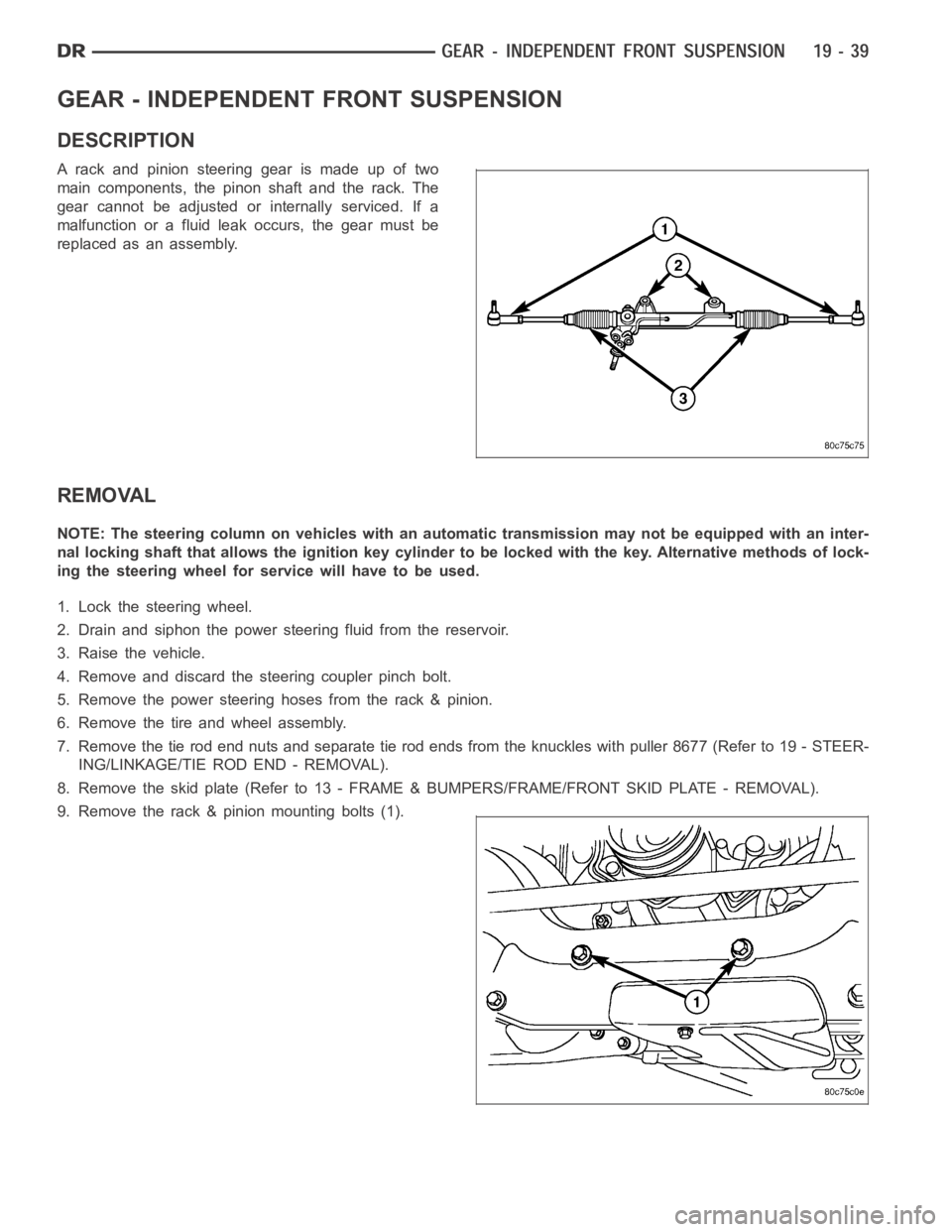
GEAR - INDEPENDENT FRONT SUSPENSION
DESCRIPTION
A rack and pinion steering gear is made up of two
main components, the pinon shaft and the rack. The
gear cannot be adjusted or internally serviced. If a
malfunction or a fluid leak occurs, the gear must be
replaced as an assembly.
REMOVAL
NOTE: The steering column on vehicles with an automatic transmission may not be equipped with an inter-
nal locking shaft that allows the ignition key cylinder to be locked with the key. Alternative methods of lock-
ing the steering wheel for service will have to be used.
1. Lock the steering wheel.
2. Drain and siphon the power steering fluid from the reservoir.
3. Raise the vehicle.
4. Remove and discard the steering coupler pinch bolt.
5. Remove the power steering hoses from the rack & pinion.
6. Remove the tire and wheel assembly.
7. Remove the tie rod end nuts and separate tie rod ends from the knuckles withpuller8677(Referto19-STEER-
ING/LINKAGE/TIE ROD END - REMOVAL).
8. Remove the skid plate (Refer to 13 - FRAME & BUMPERS/FRAME/FRONT SKID PLATE - REMOVAL).
9. Remove the rack & pinion mounting bolts (1).
Page 2449 of 5267

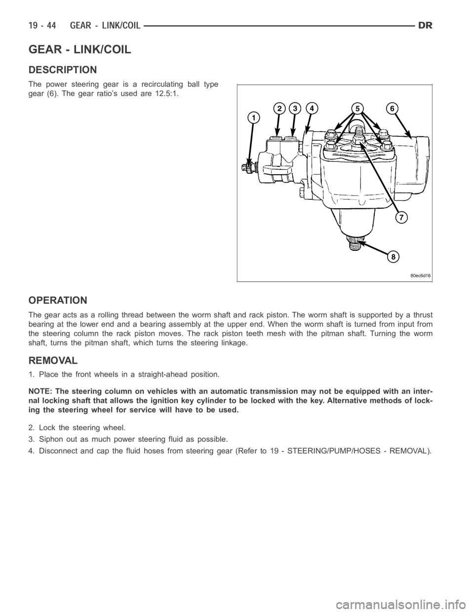
GEAR - LINK/COIL
DESCRIPTION
The power steering gear is a recirculating ball type
gear (6). The gear ratio’s used are 12.5:1.
OPERATION
The gear acts as a rolling thread between the worm shaft and rack piston. Theworm shaft is supported by a thrust
bearing at the lower end and a bearing assembly at the upper end. When the worm shaft is turned from input from
the steering column the rack piston moves. The rack piston teeth mesh with the pitman shaft. Turning the worm
shaft, turns the pitman shaft, which turns the steering linkage.
REMOVAL
1. Place the front wheels in a straight-ahead position.
NOTE: The steering column on vehicles with an automatic transmission may not be equipped with an inter-
nal locking shaft that allows the ignition key cylinder to be locked with the key. Alternative methods of lock-
ing the steering wheel for service will have to be used.
2. Lock the steering wheel.
3. Siphon out as much power steering fluid as possible.
4. Disconnect and cap the fluid hoses from steering gear (Refer to 19 - STEERING/PUMP/HOSES - REMOVAL).
Page 2452 of 5267

ADJUSTMENTS
ADJUSTMENT
CAUTION: Steering gear must be adjusted in the proper order. If adjustments are not performed in order,
gear damage and improper steering response may result.
NOTE: Adjusting the steering gear in the vehicle is not recommended. Remove gear from the vehicle and
drain the fluid. Then mount gear in a vise to perform adjustments.
1. Remove the steering gear from the vehicle(Referto19-STEERING/GEAR-REMOVAL).
2. Mount the gear carefully into a soft-jawed vise.
CAUTION: Do not overtighten the vise on the gear case. This may affect the adjustment
3. Hold the steering gear upside down over a drain pan and rotate the input shaft back and forth several times
lock-to-lock to discharge the fluid from the steering gear
4. Rotate the input shaft to the left stop and then back-off approximately 45 degrees. Using an inch-pound torque
wrench on the input shaft, record the peak torque required to slowly and evenly rotate the input shaft clockwise
1⁄2turn (180 degrees) starting from the 45 degree position. This peak torque reading is the preload torque. The
preload torque must be within 2 - 10 in-lbs.
5. Rotate the input shaft to its center of travel (approximately 1.5 turns from either stop). Place the torque wrench
on the input shaft with the handle in the vertical position. Rotate the torque wrench slowly and evenly
1⁄4turn (90
degrees) each side of center and record the peak torque measure on or near center. This total on-center torque
reading must be 5 - 9 in-lbs higher than the previously measured preload torque without exceeding a total of 17
in-lbs. The value of the total on-center minus the preload torque is defined as the meshload torque
6. If required, adjust the on-center torque by loosening the adjuster screw lock nut and turning the adjuster screw
until the total on-center and meshload torque readings fall within the specified values. Turn the adjuster screw
clockwise to increase and counterclockwise to decrease the torque reading. While holding the adjuster screw in
place, tighten the lock nut to 34 Nꞏm (25 ft. lbs.).
7. Re-check the preload and on-center torque readings.
8. Install pitman arm on the steering gear (Refer to 19 - STEERING/LINKAGE/PITMAN ARM - INSTALLATION).
9. Reinstall steering gear to the vehicle (Refer to 19 - STEERING/GEAR - INSTALLATION).
SPECIFICATIONS
POWER STEERING GEAR
SPECIFICATIONS
DESCRIPTION SPECIFICATION
Steering Gear
Ty peRecirculating Ball
Gear Code & Ratio 12.5:1
TORQUE
DESCRIPTION Nꞏm Ft. Lbs. In. Lbs.
Preload
To r q u e0.23-1.13 — 2-10
Meshload Torque 0.56-1.02 — 5-9
+ Preload (17 Max)
Page 2453 of 5267
TORQUE
DESCRIPTION Nꞏm Ft. Lbs. In. Lbs.
Steering Gear Mounting
Frame Bolts196 145 —
Steering Coupler to Gear
Shaft49 36 —
Power Steering Line
Pressure32 23 —
Power Steering Line
Return54 40 —
Power Steering Line
Pressure Line To Pump37 27 —
Steering Gear
Adjustment Screw Locknut34 25 —
Steering Gear
Pitman Shaft Nut305 225 —
Steering Gear
Pitman Shaft Cover Bolts68 50 —
Steering Gear
Valve Housing to Gear
Bolts54 40 —
Steering Gear
Retainer Ring Screw2.26 — 20
Steering Gear
Retainer Ring97 72 —