2006 DODGE RAM SRT-10 lock
[x] Cancel search: lockPage 2459 of 5267
STEERING GEAR INPUT SHAFT SEAL
REMOVAL
1. Remove the steering gear from the vehicle(Referto19-STEERING/GEAR-REMOVAL).
CAUTION: Do not overtighten the vise on the gear case. This may affect the adjustment
2. Mount the steering gear upside down over a drain pan in a soft jawed vise.
3. Place a drain pan under the gear and rotate the input shaft back and forth several times lock-to-lock to discharge
the fluid from the steering gear
4. Drain all the remaining fluid from the gear.
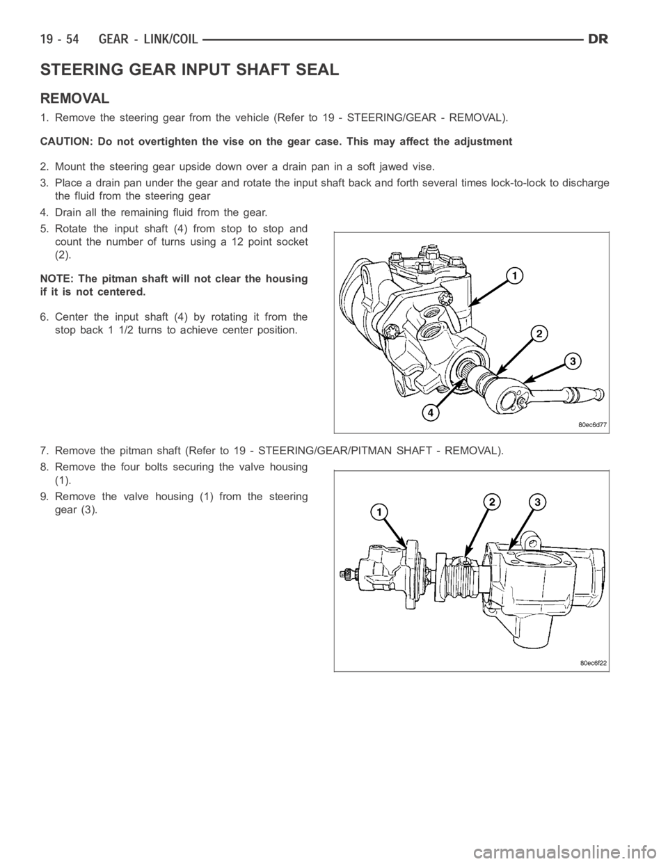
5. Rotate the input shaft (4) from stop to stop and
count the number of turns using a 12 point socket
(2).
NOTE: The pitman shaft will not clear the housing
if it is not centered.
6. Center the input shaft (4) by rotating it from the
stop back 1 1/2 turns to achieve center position.
7. Remove the pitman shaft (Refer to 19 - STEERING/GEAR/PITMAN SHAFT - REMOVA L ) .
8. Remove the four bolts securing the valve housing
(1).
9. Remove the valve housing (1) from the steering
gear (3).
Page 2478 of 5267
INSTALLATION
1. Align reference marks and install pitman arm.
2. Install the lock washer and retaining nut on the pit-
man shaft and tighten nut to 251 Nꞏm (185 ft. lbs.).
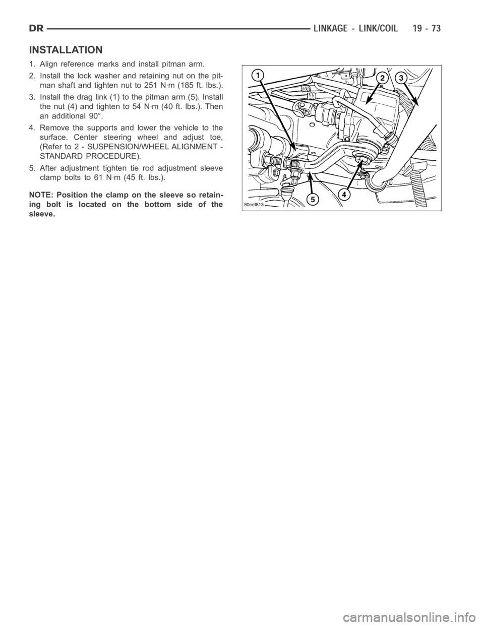
3. Install the drag link (1) to the pitman arm (5). Install
thenut(4)andtightento54Nꞏm(40ft.lbs.).Then
an additional 90°.
4. Remove the supports and lower the vehicle to the
surface. Center steering wheel and adjust toe,
(Refer to 2 - SUSPENSION/WHEEL ALIGNMENT -
STANDARD PROCEDURE).
5. After adjustment tighten tie rod adjustment sleeve
clamp bolts to 61 Nꞏm (45 ft. lbs.).
NOTE:Positiontheclamponthesleevesoretain-
ing bolt is located on the bottom side of the
sleeve.
Page 2483 of 5267
1. Raise the front end of the vehicle off the ground until the wheels are freeto turn.
2. Remove the return line from the pump.
NOTE: If vehicle is equipped with a hydraulic booster remove both return lines from the pump.
3. Plug the return line port/ports at the pump.
4. Position the return line/lines into a large container to catch the fluid.
5. While an assistant is filling the pump reservoir start the engine.
6. With the engine running at idle turn the wheel back and forth.
NOTE: Do not contact or hold the wheel against the steering stops.
7. Run a quart of fluid through the system then stop the engine and install the return line/lines.
8. Fill the system with fluid and perform Steering Pump Initial Operation,(Refer to 19 - STEERING/PUMP - STAN-
DARD PROCEDURE).
9. Start the engine and run it for fifteen minutes then stop the engine.
10. Remove the return line/lines from the pump and plug the pump port/ports.
11. Pour fresh fluid into the reservoir and check the draining fluid for contamination. If the fluid is still contaminated,
then flush the system again.
12. Install the return line/lines and perform Steering Pump Initial Operation, (Refer to 19 - STEERING/PUMP -
STANDARD PROCEDURE).
POWER STEERING PUMP - INITIAL OPERATION
WARNING: THE FLUID LEVEL SHOULD BE CHECKED WITH ENGINE OFF TO PREVENT INJURYFROMMOV-
ING COMPONENTS.
CAUTION: MOPAR
ATF+4 is to be used in the power steering system. No other power steering or auto-
matic transmission fluid is to be used in the system. Damage may result to the power steering pump and
system if any other fluid is used, and do not overfill.
Wipe filler cap clean, then check the fluid level. The dipstick should indicateCOLDwhen the fluid is at normal
temperature.
1. Turn steering wheel all the way to the left.
2. Fill reservoir up to FULL HOT level and crank engine until it just starts.(DO NOT TURN STEERING WHEEL).
Then turn vehicle off. And recheck fluid level, to Full COLD.
3. Crank engine again until it just starts, (DO NOT MOVE STEERING WHEEL). and turn vehicle off. Recheck fluid
leveltoFullCOLD.
4. Turn engine on again, (DO NOT MOVE STEERING WHEEL) and let the vehicle idle for 5 minutes. If possible
apply a 20 in-Hg vacuum to the reservoir, while engine is idling.
5. Turn engine off and recheck fluid level, to FULL COLD.
6.If the Steering gear is replacedensure reservoir is at FULL HOT level, start engine and turn wheel to left. Stop
Engine and recheck fluid level to FULL HOT. Start engine and turn wheel to the right. Stop engine and check
fluid level is at FULL COLD.
7. Fill the pump fluid reservoir to the proper level and let the fluid settlefor at least two (2) minutes.
8. Start the engine. With the engine idling maintain the fluid level.
9. Raise the front wheels off the ground.
10. Slowly turn the steering wheel lock-to-lock 20 times with the engine off while checking the fluid level.
NOTE: For vehicles with long return lines or oil coolers turn wheel 40 times.
11. Lower the front wheels and let the engine idle for two minutes.
12. Turn the steering wheel in both direction and verify power assist and quiet operation of the pump.
If the fluid is extremely foamy or milky looking, allow the vehicle to standa few minutes and repeat the procedure.
Page 2484 of 5267
CAUTION: Do not run a vehicle with foamy fluid for an extended period. This may cause pump damage.
REMOVAL
GAS ENGINE
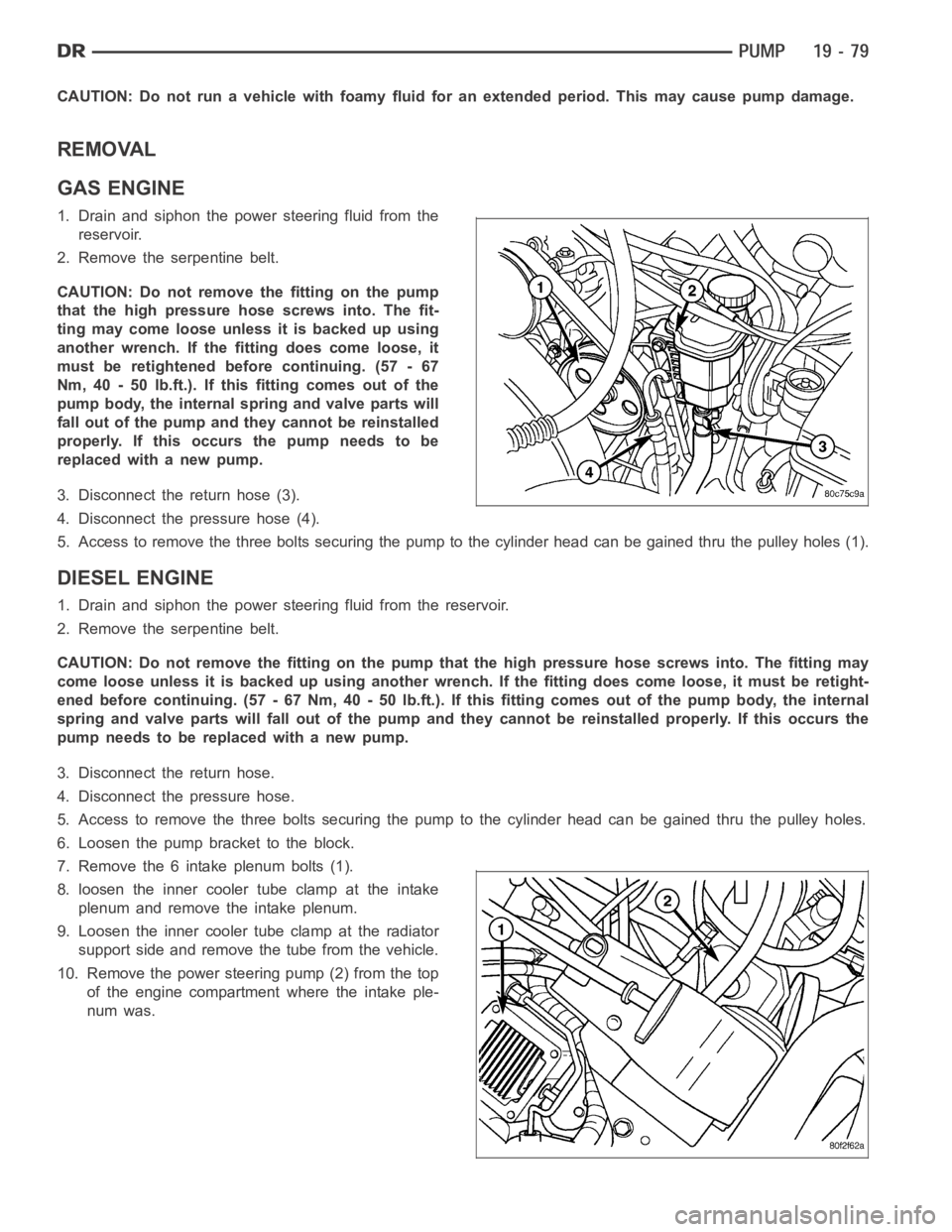
1. Drain and siphon the power steering fluid from the
reservoir.
2. Remove the serpentine belt.
CAUTION: Do not remove the fitting on the pump
that the high pressure hose screws into. The fit-
ting may come loose unless it is backed up using
another wrench. If the fitting does come loose, it
must be retightened before continuing. (57 - 67
Nm, 40 - 50 lb.ft.). If this fitting comes out of the
pump body, the internal spring and valve parts will
fall out of the pump and they cannot be reinstalled
properly. If this occurs the pump needs to be
replaced with a new pump.
3. Disconnect the return hose (3).
4. Disconnect the pressure hose (4).
5. Access to remove the three bolts securing the pump to the cylinder head can be gained thru the pulley holes (1).
DIESEL ENGINE
1. Drain and siphon the power steering fluid from the reservoir.
2. Remove the serpentine belt.
CAUTION: Do not remove the fitting on the pump that the high pressure hose screws into. The fitting may
come loose unless it is backed up using another wrench. If the fitting does come loose, it must be retight-
ened before continuing. (57 - 67 Nm, 40 - 50 lb.ft.). If this fitting comes out of the pump body, the internal
spring and valve parts will fall out of the pump and they cannot be reinstalled properly. If this occurs the
pump needs to be replaced with a new pump.
3. Disconnect the return hose.
4. Disconnect the pressure hose.
5. Access to remove the three bolts securing the pump to the cylinder head can be gained thru the pulley holes.
6. Loosen the pump bracket to the block.
7. Remove the 6 intake plenum bolts (1).
8. loosen the inner cooler tube clamp at the intake
plenum and remove the intake plenum.
9. Loosen the inner cooler tube clamp at the radiator
support side and remove the tube from the vehicle.
10. Remove the power steering pump (2) from the top
of the engine compartment where the intake ple-
num was.
Page 2485 of 5267
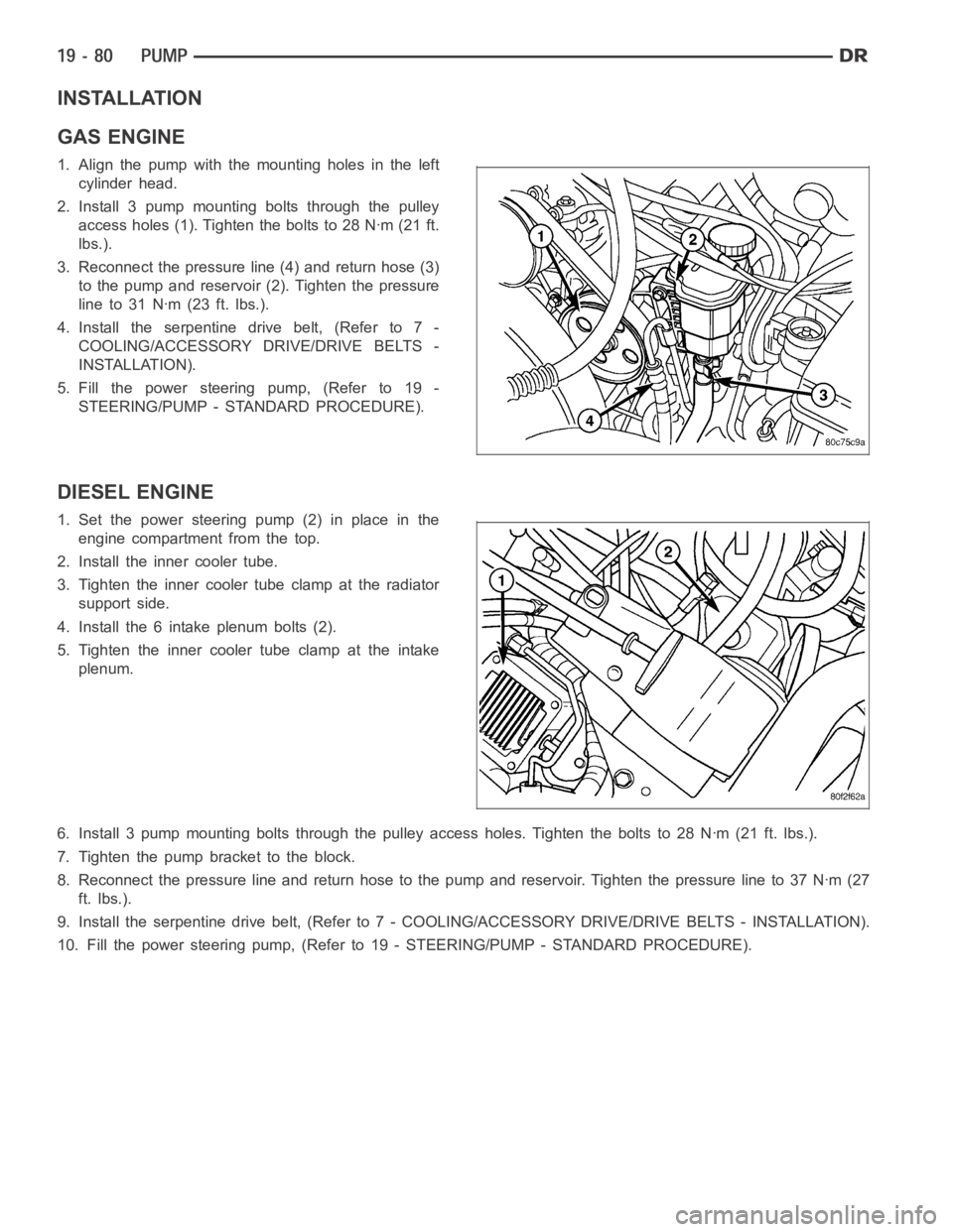
INSTALLATION
GAS ENGINE
1. Align the pump with the mounting holes in the left
cylinder head.
2. Install 3 pump mounting bolts through the pulley
access holes (1). Tighten the bolts to 28 Nꞏm (21 ft.
lbs.).
3. Reconnect the pressure line (4) and return hose (3)
to the pump and reservoir (2). Tighten the pressure
line to 31 Nꞏm (23 ft. lbs.).
4. Install the serpentine drive belt, (Refer to 7 -
COOLING/ACCESSORY DRIVE/DRIVE BELTS -
INSTALLATION).
5. Fill the power steering pump, (Refer to 19 -
STEERING/PUMP - STANDARD PROCEDURE).
DIESEL ENGINE
1. Set the power steering pump (2) in place in the
engine compartment from the top.
2. Install the inner cooler tube.
3. Tighten the inner cooler tube clamp at the radiator
support side.
4. Install the 6 intake plenum bolts (2).
5. Tighten the inner cooler tube clamp at the intake
plenum.
6. Install 3 pump mounting bolts through the pulley access holes. Tighten theboltsto28Nꞏm(21ft.lbs.).
7. Tighten the pump bracket to the block.
8. Reconnect the pressure line and return hose to the pump and reservoir. Tightenthepressurelineto37Nꞏm(27
ft. lbs.).
9. Install the serpentine drive belt, (Refer to 7 - COOLING/ACCESSORY DRIVE/DRIVE BELTS - INSTALLATION).
10. Fill the power steering pump, (Refer to 19 - STEERING/PUMP - STANDARD PROCEDURE).
Page 2500 of 5267
STANDARD PROCEDURE
INITIAL OPERATION
WARNING: The fluid level should be checked with engine off to prevent injury from moving components.
NOTE: Remove as much of the old fluid out of the system as possible with a suction tool or by removing
a hose, when a component has failed. Then refill it with fresh fluid until itis clean. This may have to be
done more than once.
CAUTION: MOPAR
ATF+4 is to be used in the power steering system. No other power steering or auto-
matic transmission fluid is to be used in the system. Damage may result to the power steering pump and
system if any other fluid is used, and do not overfill.
Wipe filler cap clean, then check the fluid level. The dipstick should indicateCOLDwhen the fluid is at normal
ambient temperature.
1. Fill the pump fluid reservoir to the proper level and let the fluid settlefor at least two minutes.
2. Start the engine and let run for a few seconds then turn engine off.
3. Add fluid if necessary. Repeat the above procedure until the fluid levelremains constant after running the engine.
4. Raise the front wheels off the ground.
5. Slowly turn the steering wheel right and left, lightly contacting the wheel stops at least 20 times.
6. Check the fluid level add if necessary.
7. Lower the vehicle, start the engine, and use the DRB III to activate the hydraulic fan on full fan operation.
8. Turn the steering wheel slowly from lock to lock.
9. Stop the engine, check the fluid level and refill as required and repeat the process
CAUTION: Do not run a vehicle with foamy fluid for an extended period. This may cause pump damage.
10. If the fluid is extremely foamy or milky looking, allow the vehicle to stand a few minutes and repeat the pro-
cedure.
11. While the vehicle is in park, use the DRB III to activate the hydraulic fan to full fan operation and briefly rev the
engine up to 3000 rpm to fully engage the hydraulic fan.
12. Check the fluid level add if necessary.
Page 2510 of 5267
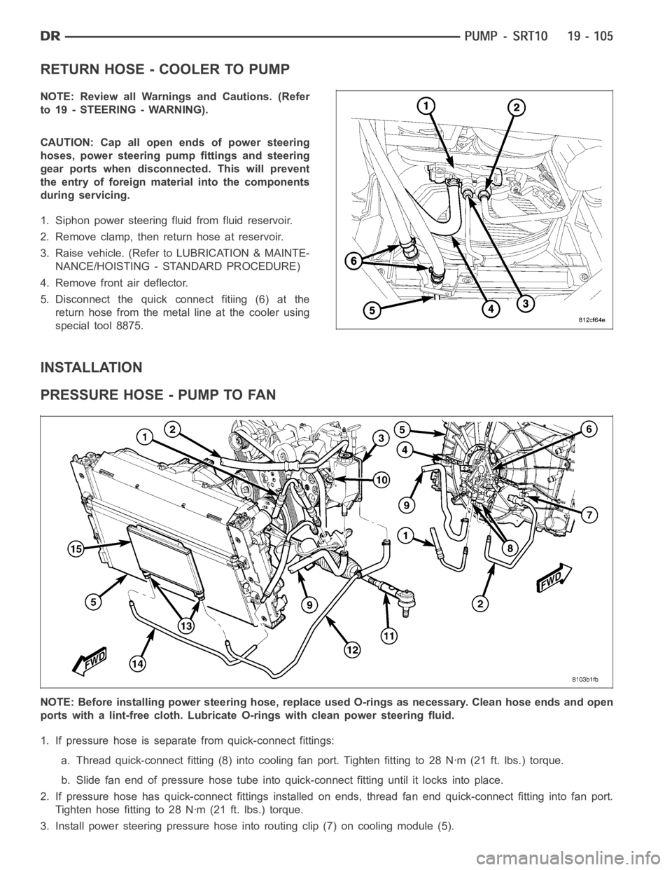
RETURN HOSE - COOLER TO PUMP
NOTE: Review all Warnings and Cautions. (Refer
to 19 - STEERING - WARNING).
CAUTION: Cap all open ends of power steering
hoses, power steering pump fittings and steering
gear ports when disconnected. This will prevent
the entry of foreign material into the components
during servicing.
1. Siphon power steering fluid from fluid reservoir.
2. Remove clamp, then return hose at reservoir.
3. Raise vehicle. (Refer to LUBRICATION & MAINTE-
NANCE/HOISTING - STANDARD PROCEDURE)
4. Remove front air deflector.
5. Disconnect the quick connect fitiing (6) at the
return hose from the metal line at the cooler using
special tool 8875.
INSTALLATION
PRESSURE HOSE - PUMP TO FAN
NOTE: Before installing power steering hose, replace used O-rings as necessary. Clean hose ends and open
ports with a lint-free cloth. Lubricate O-rings with clean power steeringfluid.
1. If pressure hose is separate from quick-connect fittings:
a. Thread quick-connect fitting (8) into cooling fan port. Tighten fittingto28Nꞏm(21ft.lbs.)torque.
b. Slide fan end of pressure hose tube into quick-connect fitting until it locks into place.
2. If pressure hose has quick-connect fittings installed on ends, thread fan end quick-connect fitting into fan port.
Tighten hose fitting to 28 Nꞏm (21 ft. lbs.) torque.
3. Install power steering pressure hose into routing clip (7) on cooling module (5).
Page 2511 of 5267
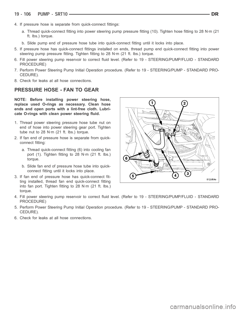
4. If pressure hose is separate from quick-connect fittings:
a. Thread quick-connect fitting into power steering pump pressure fitting (10). Tighten hose fitting to 28 Nꞏm (21
ft. lbs.) torque.
b. Slide pump end of pressure hose tube into quick-connect fitting until itlocks into place.
5. If pressure hose has quick-connect fittings installed on ends, thread pump end quick-connect fitting into power
steering pump pressure fitting. Tighten fitting to 28 Nꞏm (21 ft. lbs.) torque.
6. Fill power steering pump reservoir to correct fluid level. (Refer to 19 -STEERING/PUMP/FLUID - STANDARD
PROCEDURE)
7. Perform Power Steering Pump Initial Operation procedure. (Refer to 19 -STEERING/PUMP - STANDARD PRO-
CEDURE).
8. Check for leaks at all hose connections.
PRESSURE HOSE - FAN TO GEAR
NOTE: Before installing power steering hose,
replace used O-rings as necessary. Clean hose
ends and open ports with a lint-free cloth. Lubri-
cate O-rings with clean power steering fluid.
1. Thread power steering pressure hose tube nut on
end of hose into power steering gear port. Tighten
tube nut to 28 Nꞏm (21 ft. lbs.) torque.
2. If fan end of pressure hose is separate from quick-
connect fitting:
a. Thread quick-connect fitting (6) into cooling fan
port (1). Tighten fitting to 28 Nꞏm (21 ft. lbs.)
torque.
b. Slide fan end of pressure hose tube into quick-
connect fitting until it locks into place.
3. If fan end of pressure hose has quick-connect fit-
ting installed, thread fan end quick-connect fitting
into fan port. Tighten fitting to 28 Nꞏm (21 ft. lbs.)
torque.
4. Fill power steering pump reservoir to correct fluid level. (Refer to 19 -STEERING/PUMP/FLUID - STANDARD
PROCEDURE)
5. Perform Power Steering Pump Initial Operation procedure. (Refer to 19 -STEERING/PUMP - STANDARD PRO-
CEDURE).
6. Check for leaks at all hose connections.