Page 2649 of 5267
28. Install main shift rail (1) bearings (2) on main shift
rail.
29. Install main shift rail (1) through rail support (2)
and housing, then rotate counterclockwise into
place.
30. Install 1-2 shift fork then, install 1-2 shift rail (2)
into shift fork and housing. Install shift fork roll pin
(1).
Page 2655 of 5267
50. Install countershaft bolt (1) in front housing.
Tighten bolt (1) to 90 Nꞏm (66 ft. lbs.).
51. Install countershaft plug in front housing (1) with
Installer 9622 (2) and Handle C-4171.
52. Install the cover plate for the second shift tower
location, if necessary.
53. Apply Mopar
Lock & Seal or equivalent to shifter
socket threads and install shifter socket (1).
Page 2657 of 5267

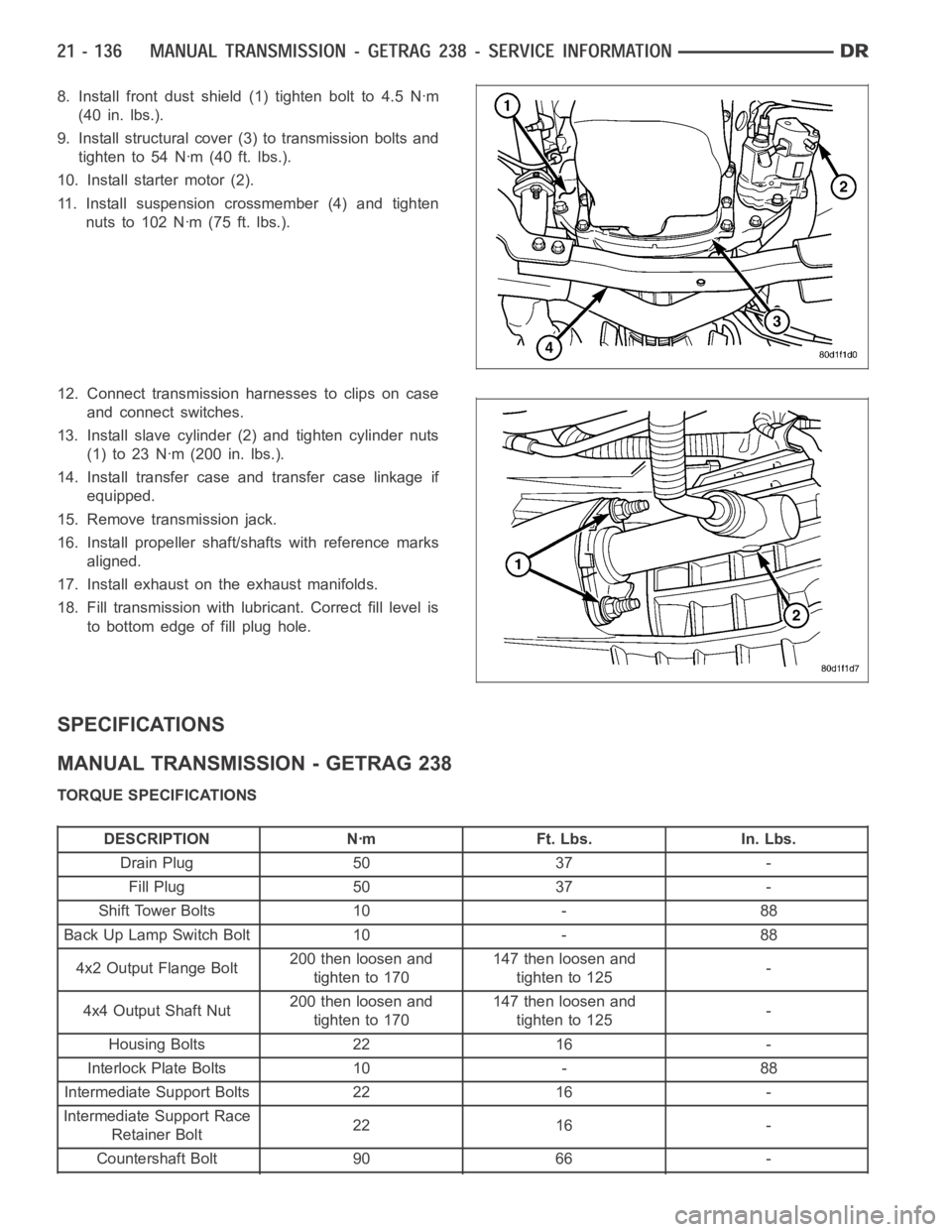
8. Install front dust shield (1) tighten bolt to 4.5 Nꞏm
(40 in. lbs.).
9. Install structural cover (3) to transmission bolts and
tighten to 54 Nꞏm (40 ft. lbs.).
10. Install starter motor (2).
11. Install suspension crossmember (4) and tighten
nuts to 102 Nꞏm (75 ft. lbs.).
12. Connect transmission harnesses to clips on case
and connect switches.
13. Install slave cylinder (2) and tighten cylinder nuts
(1)to23Nꞏm(200in.lbs.).
14. Install transfer case and transfer case linkage if
equipped.
15. Remove transmission jack.
16. Install propeller shaft/shafts with reference marks
aligned.
17. Install exhaust on the exhaust manifolds.
18. Fill transmission with lubricant. Correct fill level is
to bottom edge of fill plug hole.
SPECIFICATIONS
MANUAL TRANSMISSION - GETRAG 238
TORQUE SPECIFICATIONS
DESCRIPTION Nꞏm Ft. Lbs. In. Lbs.
Drain Plug 50 37 -
Fill Plug 50 37 -
Shift Tower Bolts 10 - 88
Back Up Lamp Switch Bolt 10 - 88
4x2 Output Flange Bolt200 then loosen and
tighten to 170147 then loosen and
tighten to 125-
4x4 Output Shaft Nut200 then loosen and
tighten to 170147 then loosen and
tighten to 125-
Housing Bolts 22 16 -
Interlock Plate Bolts 10 - 88
Intermediate Support Bolts 22 16 -
Intermediate Support Race
Retainer Bolt22 16 -
Countershaft Bolt 90 66 -
Page 2663 of 5267

page page
MANUAL TRANSMISSION-T56 - SERVICE
INFORMATION
DIAGNOSIS AND TESTING
MANUAL TRANSMISSION - T56 ............. 143
STANDARD PROCEDURE - DRAIN AND FILL . . 143
REMOVAL ................................... 144
DISASSEMBLY .............................. 146
CLEANING .................................. 168
INSPECTION ................................ 168
ASSEMBLY .................................. 169
INSTALLATION .............................. 189
ADJUSTMENTS
ADUSTMENTS ............................ 191
SPECIFICATIONS
MANUAL TRANSMISSION - T56 ............. 192SPECIAL TOOLS ............................ 194
SEAL-EXTENSION HOUSING
REMOVAL ................................... 198
INSTALLATION .............................. 198
SHAFT-INPUT
REMOVAL ................................... 199
INSTALLATION .............................. 200
SOLENOID-REVERSE LOCKOUT
DESCRIPTION ............................... 201
OPERATION ................................. 201
SOLENOID-REVERSE LOCK-OUT
DESCRIPTION ............................... 202
OPERATION ................................. 202
Page 2666 of 5267
6. Remove reverse lockout solenoid (1) connector (2).
7. Remove fuel line clipfrom top plate stud.
8. Remove back up lamp switch (2) connector (1).
9. Position transmission jack (2) and secure to trans-
mission (1).
10. Remove transmission to clutch housing bolts.
Page 2670 of 5267
9. Remove reverse gear (3), bearing (5), wave
washer (2) and brass reverse blocker ring (1) from
mainshaft (4).
10. Tap reverse synchronizer (3) on mainshaft (2) to
relieve pressure on snap ring and remove snap
ring.
11. Remove reverse shift fork (1) snap ring (2) with
snap ring pliers (3) and discard snap ring.
Page 2675 of 5267
24. Remove top cover plate (2) bolts and pry off
cover.
25. Remove shift detent (1) assembly.
26. Drive roll pin down with punch (1) into front offset
lever (3) until loose.
27. Remove reverse lockout solenoid
28. Separate offset lever and guide plate to remove
the roll pin that was driven down.
Page 2680 of 5267
3. Remove first gear (1) and bearing (2) from
mainshaft.
4. Remove 1-2 synchronizer (1) snap ring (2) from
mainshaft.
5. Remove 1-2 thrust washer (1) and blocker ring
assembly from mainshaft.